Table of Contents
Advertisement
Quick Links
Advertisement
Table of Contents

Related Manuals for Friant NOVO


Summary of Contents for Friant NOVO
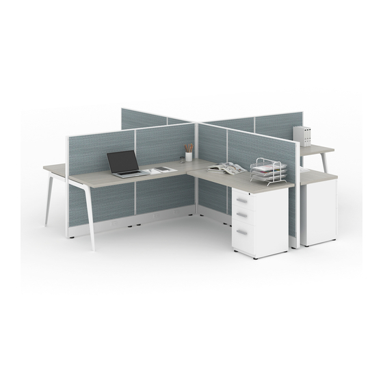
- Page 1 NOVO INSTALLATION MANUAL friant.com/Novo...
- Page 3 NOVO INSTALLATION MANUAL General Information ��������������������������������������������������������������������������������������������������� 4 Safety & Support ��������������������������������������������������������������������������������������������������������� 5 Installation Tools ���������������������������������������������������������������������������������������������������������� 6 Staging & Installation ������������������������������������������������������������������������������������������������ 7 Panels & Connectors ������������������������������������������������������������������������������������������������� 8 Electrical ������������������������������������������������������������������������������������������������������������������������� 18 Base & Trim Cover ���������������������������������������������������������������������������������������������������� 25 Shelves & Overhead Storage ������������������������������������������������������������������������������� 27 Triangle Leg and P-Leg Installation�������������������������������������������������������������������34...
-
Page 4: General Information
Friant’s Novo product. the instructions in this manual can result in product damage, The Novo product line is a modular panel system composed of personal injury or both. panels, hanging and freestanding components and accessories designed to be precisely tailored to the office environment� It consists of products that are factory assembled and require installation only;... -
Page 5: Safety & Support
Many products weigh more than 35 pounds� Use ƒ two or more people to safely lift, carry and install the products� When using tools, extension cords or ladders, use ƒ them in accordance to OSHA guidelines� Work safe, work smart� ƒ Novo Installation Manual... -
Page 6: Installation Tools
INSTALLATION TOOLS INSTALLATION TOOLS The following tools are necessary for field assembly The following tools will help speed up installations, and installation of Friant’s Novo product: but are not necessary: ƒ Allen wrench 1/4” ƒ Drill (12v or more) #2 Phillips head screwdriver Set of drill bits ƒ... -
Page 7: Staging & Installation
(with photo to document)� Keep and maintain a clutter-free staging area — it will help speed up your assembly� Protect all building walls with furniture pads or cardboard where product is leaning against them or in high traffic areas� Novo Installation Manual... -
Page 8: Panels & Connectors
Drywall must be at least 5/8” thick� Wall must be restrained at the floor and ceiling, and should be no more than 24” on center or 14’ high� Under no circumstances does Friant accept responsibility for determination of the structural integrity of a load bearing wall�... - Page 9 There are three types of draw rods: Panel to Panel, Same Height draw rod ƒ Panel to Panel, Change of Height draw rod ƒ Wall Start/Power Pole draw rod ƒ Same Height Draw Rod Change of Height Draw Rod Novo Installation Manual...
- Page 10 PANELS & CONNECTORS PANEL TO PANEL — CHANGE OF HEIGHT Change of height draw rod includes a draw rod and a hanger rail of the same height. 1. Remove top block and hanger rail from taller panel� IMAGE A, B, C 2.
- Page 11 6. Slide modified finished end onto the screws� IMAGE C 7. Final installed product� IMAGE D WARNING : It is very important at this point in the installation to re-check all connections to ensure safety and security. Novo Installation Manual...
- Page 12 PANELS & CONNECTORS PANEL TO PANEL — CHANGE OF HEIGHT TRIM 1. Install top cap on the lower panel� IMAGE A 2. Insert bottom of change of height trim support inside the side rail and push down to rest on lower top cap� 3.
-
Page 13: Electrical
4. You now have the start of your first station� TIP: Start at a right angle condition in your layout. It is recommended that you identify the location using your plan to locate the connection in the office area. Novo Installation Manual... - Page 14 PANELS & CONNECTORS PANEL TO CONNECTOR — CHANGE OF HEIGHT 1. When installing a change of height connection, you must remove the black filler strip on the side of the connector you are going to attach the panel to� Always use the connector for the tallest panel you are attaching to�...
- Page 15 CHANGE OF HEIGHT - HARDWARE PACKAGE Panel to Connector Panel to Panel Hardware Hardware 4 machine screws 4 wood screws 2 thread plates NOTE: 8”H sizes require only two screws. All other sizes will require four screws. Novo Installation Manual...
- Page 16 PANELS & CONNECTORS TOP CAP INSTALLATION top cap Before installing the top caps, please ensure that all connectors have been installed and all panels are leveled. 1. Angle top cap to engage one side first, then rotate toward the other side and snap the top cap onto the top cap holder�...
- Page 17 Example of Incorrect Leveling: Example of Correct Leveling: Top Blocks leveled incorrectly result in Top Caps aligned uneven top caps for panel to connector Top Blocks at Top Blocks same heights Top Blocks at dif- ferent heights Novo Installation Manual...
- Page 18 PANELS & CONNECTORS WALL STARTS Wall start applications require some additional tools. The most important are a good tape measure, level and drill. The wall should be reinforced to prevent damage or injury. 1. Locate on your plan the wall start� Measure the wall, and very lightly with a pencil, mark the location of the wall start�...
- Page 19 Side Rail Install 2 screws to secure bottom plastic block to the pre-drilled holes Bottom Plastic Block Flip bottom plastic block against the bottom end of the side rail Hook Bottom Plastic Block to Base Plate cutout Novo Installation Manual...
- Page 20 FINISHED END SINGLE PIECE SINGLE PIECE FINISHED END INSTALLATION CON’T Pre-drilled holes in side rail Single Piece Finished End Bottom Plastic Block installed on Side Rail a Two Piece Side Rail with pre-drilled holes 1. Tilt the bottom plastic block to insert its hook into the bottom base plate cutout�...
- Page 21 Mark the 2 as a final step holes to drill into side rail. Flip bottom plastic block against the bottom end of the side rail Novo Installation Manual...
- Page 22 FINISHED END SINGLE PIECE SINGLE PIECE FINISHED END INSTALLATION CON’T Top Block 1. Install Single Piece Finished End� IMAGE E • Loosen top block at top of the finished end� Finished End • Engage bottom block on finished end into bottom plastic block�...
- Page 23 4. Align top cap with edge of finished end trim, and snap onto top cap support� IMAGE H Top Cap 5. Finished installation� IMAGE I Top Cap Support Panel Finished End Trim Finished installation Novo Installation Manual...
- Page 24 PANEL TO PANEL CHANGE OF HEIGHT DRAW ROD SINGLE PIECE SIDE RAIL CHANGE OF HEIGHT DRAW ROD 1. Insert the metal ‘teeth’ into the slots in the side of the taller panel� IMAGES A & B 2. Align top block of draw rod with the top of the shorter panel�...
- Page 25 2. Push panel to panel change of height trim into in until it is secured the side of the taller panel until it is secured� IMAGE B Push change of height trim into the side of the taller panel Novo Installation Manual...
- Page 26 Festoons are used to carry the electrical power from power harness to power harness� A qualified electrician is an individual either licensed or recognized by the local building code authorities to properly wire the Novo power system to the existing building power� WARNING : Never attempt to...
- Page 27 90° angle through a 2-Way, 3-Way or 4-Way connector NOTE: The festoon part number can be found on the UL sticker. WARNING : Failure to follow the wiring diagram can result in personal injury, product damage, or both. Novo Installation Manual...
- Page 28 ELECTRICAL FESTOON INSTALLATION Once you have installed the panels and connectors and have leveled the system, you can begin to install the festoons. There are three types: • Panel to panel festoon • Panel through post festoon • 90° Angle festoon 1.
- Page 29 We recommend bundling and laying cables as shown below to accommodate the slim base. Glide Post Glide Post Data Cables split half on Bundled Data Cables each side of glide post (max 5 cables in each bundle) (max 10 cables per side) Novo Installation Manual...
- Page 30 ELECTRICAL RECEPTACLE INSTALLATION 1. Insert the receptacle into the side of the power harness, with the number in the “up” position� IMAGE A NOTE: The arrow on the festoon must be in the “up” position. Do not force the connection. 2.
- Page 31 WARNING : Power entries should not be installed by any person(s) other than a qualified electrician. Attempting to do so can result in electric shock, personal injury, product damage, property damage or death. Novo Installation Manual...
- Page 32 ELECTRICAL BASE POWER ENTRY NOTE: The installation of the power entries, both ceiling feed and base power entry, must be made by a qualified electrician. The purpose of this installation instruction is to assist you in working with the electrician to have this product installed. Under no circumstances should this be attempted by a person not recognized by local building authorities as a qualified electrician.
-
Page 33: Base & Trim Cover
3. Gently tuck the lip on the top of the raceway cover under the metal edge at the bottom of the panel until the magnets touch� 4. When finished, the raceway cover will stay in place by itself� Novo Installation Manual... - Page 34 BASE & TRIM COVER FINISHED END TRIM COVER 1. Locate the tabs at the bottom of the raceway end caps� Place the tabs into the holes in the raceway at an end cap location� IMAGE A 2. Rotate the end cap up to the bottom of the panel� Lock end cap into the tab at the bottom of the panel�...
-
Page 35: Shelves & Overhead Storage
6. Line up the slots on each side of the shelf with mounting screws on each shelf end� Press down on shelf and ensure it is fully seated on the mounting screws� IMAGE D 7. Tighten all mounting screws� Completed shelf installation� Novo Installation Manual... - Page 36 SHELVES & OVERHEAD STORAGE SLIDING DOOR OVERHEAD CABINET Install Shelf Ends 1. Position the attachment bracket over the frame or wall strip at the required height� Tabs should be facing up� 2. Rotate attachment bracket at an angle� Insert top tab into the slots on the frame or wall stips�...
- Page 37 Engage the wheels in the track� 20. Reinstall the plastic door stops� divider at top shelf divider at top shelf (view of front) (view of back) plastic door wheel cutout stop (top left) (top left) Novo Installation Manual...
- Page 38 SHELVES & OVERHEAD STORAGE PNEUMATIC OVERHEAD CABINET 1. Position the attachment bracket over the frame or wall strip at the required height� Tabs should be facing up� 2. Rotate attachment bracket at an angle� Insert top tab into the slots on the frame or wall stips� Rotate the front of the attachment bracket down to fully engage all clips and slots�...
- Page 39 Attachment Holes 4. Attach bracket extender to the upmount bracket with hardware provided� Do not tighten� Clips IMAGE B, C, D Instructions continued on next page » screws for attaching back bracket extender outside view inside view Novo Installation Manual...
-
Page 40: Storage
SHELVES & OVERHEAD STORAGE UPMOUNT SLIDING DOOR OVERHEAD CABINET, cont’d 5. Install both left and right upmount brackets at the correct height by tilting the bracket at an angle and inserting the top tabs into the frame� IMAGE E 6. Rotate both left and right upmount brackets downward upmount bracket and push down to ensure that the tabs are fully seated�... - Page 41 3. Lift Upmount Pneumatic Overhead and place onto the support bracket� IMAGE B WARNING : Use two people to safely lift and install. 4. Secure the Upmount Pneumatic Overhead to the support brackets by using the screws provided� IMAGE B Upmount Pneumatic overhead cabinet installed� Novo Installation Manual...
- Page 42 Square Metal P-Leg Installation Square Metal P-Leg Installation Worksurface support bracket. *Note: 3 screws (single sided shown WARNING: All worksurface support used to support the same worksurface must be mounted at the same height. *Note: Top Worksurface installation requires two tooth is taller people.
- Page 43 Single Support, Left NOTE: To change from left to right hand Wood suport, remove worksurface support Glides Screws bracket from the top of the Square Metal P-Leg and turn it 180°. Glides Dual Support Finished Product Friant | Interra Installation Manual...
- Page 44 Square Metal Triangle Leg Frame Installation Square Metal Triangle Leg Worksurface support Frame Installation bracket. *Note: 3 screws (single sided shown *Note: Top Warning: All worksurface support used to support the same tooth is taller worksurface must be mounted at the than others same height.
- Page 45 NOTE: For center leg installation, move LH panel attachment bracket over, so that teeth align with the middle of the square metal triangle leg frame. Move non-handed bracket over with the same alignment. Friant | Interra Installation Manual...
- Page 46 WORKSURFACES CORNER, EXTENDED CORNER, 120° AND 135° WARNING : All worksurface support used to support the same worksurface must be mounted at the same height. NOTE: Corner worksurfaces should be installed before installing adjacent worksurfaces. 1. Install the corner bracket into the corner at the desired height�...
- Page 47 IMAGE E 6. Install adjacent worksurfaces required� Attach ganging plates between adjacent worksurfaces on underside of the worksurface� IMAGE F NOTE: Rectangular worksurfaces spanning two or more panels require a center support provided. Novo Installation Manual...
- Page 48 STORAGE PEDESTALS All pedestals (except mobile pedestals) require attachment to the worksurface they are supporting. TIP: It is important that you check your pedestal height in worksurface installation. If the height is incorrect you will have to adjust the glides on the pedestal or reset the height of the worksurfaces accordingly.
- Page 49 IMAGE C 4. Carefully reinsert the drawers back into the track� TIP: Always recheck the drawers for proper operation after installing the lateral, and check to ensure the lock is working properly. Novo Installation Manual...
- Page 50 4. Reinstall the bottom drawer on the lateral file� NOTE: Counterweights can be ordered for 2, 3 and 4 drawer lateral files, however, Friant suggests you bolt 3 and 4 drawer lateral files back to back or to wall and load bottom drawer Bolt first for greater stability.
-
Page 51: Accessories
4. Insert the tackboard/markerboard screws into the teardrop holes on the tackboard bracket and slide the tackboard downward� 5. Check to make sure the tackboard/markerboard is seated correctly and level� Novo Installation Manual... - Page 52 ACCESSORIES TOOL BARS 1. Insert right side bracket at the end of the tool bar� IMAGE A 2. Insert right side bracket into the hanger frame slots at the desired height, and push down� IMAGE B 3. Insert left side bracket into the hanger frame slots, at the same height as the right side and push down�...
- Page 53 1. Insert cord manager in workstation� IMAGE A 2. Insert cord manager into hanger frame� IMAGE B Task light cord without cord manager in workstation� 3. Cord manager in place, neatly hiding cords� IMAGE C Novo Installation Manual...
- Page 54 ACCESSORIES LED TASKLIGHT NOTE: Installation differs slightly for attaching to a wood overhead vs metal overhead. Be sure to skip step #2 if attaching to a metal overhead. 1. Snap the magnet into the back of the LED tasklight — one on each end�...
- Page 55 4901 EAST 12th St / Oakland / California 94601 / T: 510.535.5113 / F: 510.535.5237 / friant.com 032017...
Need help?
Do you have a question about the NOVO and is the answer not in the manual?
Questions and answers