
Related Manuals for Edelbrock 70050


Summary of Contents for Edelbrock 70050
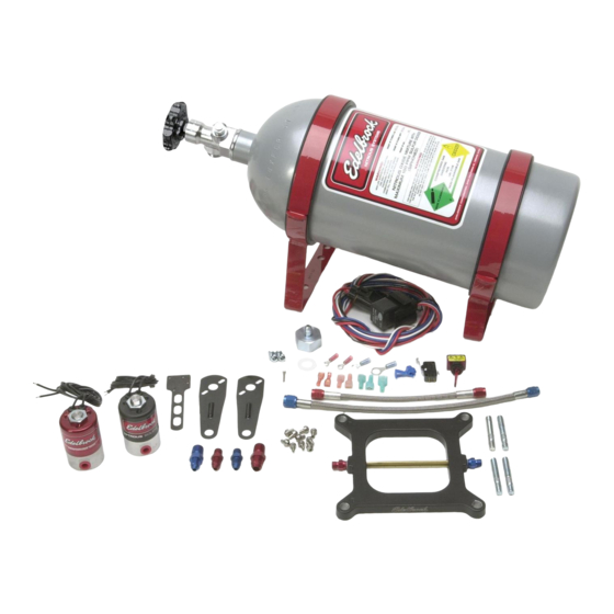
- Page 1 EDELBROCK NITROUS SYSTEMS PERFORMER RPM SERIES NITROUS SYSTEM This instruction manual supports the following Kit Part Numbers: Performer RPM Nitrous Systems #70050, #70051, and #70053...
- Page 2 With the use of nitrous oxide come some important safety considerations. This manual has been written to help you during the installation and use of your Edelbrock Nitrous System. Please read it completely before you install and use your system. Please pay close attention to the safety information at the beginning of each section.
-
Page 3: Before You Install Your Edelbrock Nitrous System
Caution!! Before You Install Your Edelbrock Nitrous System… Please read this Installation manual fully before installing this system. You will need to have available the following tools: Hand Tools Socket set including ratchets and extensions Screwdrivers Pliers Bench vise Wire crimping pliers, wire strippers... - Page 4 WHAT IS NITROUS OXIDE? Nitrous Oxide is a cryogenic gas composed of nitrogen and oxygen molecules. It is stored as a “gas over a liquid” which means that both liquid and gaseous nitrous oxide is delivered into your engine. It is 36% oxygen by weight, which is what produces the added horsepower.
- Page 5 General information The Edelbrock Performer RPM Nitrous Systems are intended for use on domestic style V-6 and V-8 engines using single square-flange 4 bbl. carburetors (Part Number 70050), spread-bore 4 bbl. carburetors (Part number 70051), and Dominator-flange carburetors (Part Number 70053). Horsepower and torque increases can vary with engine displacement and equipment upgrades and modifications.
- Page 6 6. Advanced tuning required. Suggested timing adjustment is just a guideline. Engine component modifications may affect timing. The dyno tests were conducted at Edelbrock using a mildly-modified 350 cubic-inch engine. Both dual- plane and open-plenum intake manifolds were tested to ensure validity of jetting maps for each horsepower setting.
- Page 7 When designing your fuel system, plan on your pumps and lines flowing at least 0.1 gallons per hour per horsepower at rated pressure. The testing at Edelbrock was conducted with a fuel pressure of 6.5 psi. Any variation from this fuel pressure will cause your final air/fuel ratio to change. Consult our technical department for any questions on fuel pressure and its effects on final air/fuel ratios when using nitrous oxide.
- Page 8 Performer RPM System Bill of Materials (BOM) Quantity Description Plates and Plate Hardware 1 ea Performer RPM Square-flange Plate, 70050 System 1 ea Performer RPM Spread-bore Plate, 70051 System 1 ea Performer RPM Dominator Plate, 70053 System 2 ea Square-flange gaskets, 70050 System...
- Page 9 Performer RPM System Bill of Materials (Continuation) Jets Performer RPM Square-Flange Jet Pack P/N 70050 2 ea. Jet, #57 2 ea. Jet, #68 2 ea. Jet, #78 2 ea. Jet, #85 2 ea. Jet, #99 Performer RPM Spread-Bore Jet Pack P/N 70051 2 ea.
- Page 10 It is illegal to tamper with, modify, or remove the PRD device. Bottle Safety Information 1. Do not attempt to remove the bottle valve. Please return your bottle to Edelbrock if service is required to the siphon tube inside the bottle or the bottle valve itself.
- Page 11 An Edelbrock nitrous bottle cannot be mounted upside-down. Edelbrock does not offer a non-siphon tube bottle for automotive use. If the bottle must be mounted parallel to the axles of the vehicle (sideways), the valve handle and label must be angled at approximately 45 degrees toward the front of the vehicle.
- Page 12 Bottle Installation After you have determined the location and orientation of the nitrous bottle, use the following procedure to install the bottle: 2.4.1 Street Car Installations 1. Determine the location of the bottle within the confines of the rear of the vehicle. 2.
- Page 13 Nitrous Feed Line Mounting 1. Determine the route your main nitrous feed line will follow. Ensure the path does not route the nitrous feed line too close to the exhaust system, suspension, electrical lines/components and tires. 2. Attach nitrous supply line to bottle. 3.
- Page 14 5. Leave wires loose for electrical system installation. 6. Attach nitrous feed line to solenoid. (blue fitting 4AN x 1/4 NPT). Pictured here is the Performer RPM solenoid mounted on an Edelbrock intake manifold using a modified solenoid bracket. The modifications performed to a solenoid bracket depend on many factors.
- Page 15 Nitrous/Fuel Solenoid Disassembly and Inspection 1. Close valve on nitrous bottle. 2. Empty main nitrous supply line. 3. Remove solenoid from the engine and securely clamp it into a vise, taking great care not to damage the solenoid. 4. Remove the solenoid cover-retaining nut from top of the nitrous solenoid. 5.
- Page 16 Note: Every precaution has been taken to ensure the cleanliness of our components during the assembly of your Edelbrock Nitrous System. However, because of the importance of the jets and their calibration, extra care should be taken before you install your jets.
- Page 17 2.12 Electrical System Installation Electrical Components Bill of Materials (BOM) Item Qty. Description 1 ea. Activation Microswitch 1 ea. Activation Microswitch bracket 2 ea. Activation Microswitch mounting nut (#4-40) 2 ea. Activation Microswitch mounting screw (#4-40x1") 1 ea. 30 amp relay 1 ea.
- Page 18 The wire harness attached to the relay and fuse holder includes 8 feet of color-coded wires to make the electrical system installation for your Edelbrock Nitrous System as easy as possible. We recommend you do not cut any lengths of wires from the wire harness or complete the wiring of the nitrous system until all of the mechanical components are securely mounted in their permanent locations.
- Page 20 2.14 Arming Switch The arming switch is a red, lighted switch that is a “MASTER” arming switch for your nitrous system. Without it, your nitrous system would be “on” all of the time and capable of coming on anytime you go to wide-open throttle conditions. The switch when in the “armed” position is well lit, therefore it should be placed in an obvious position, well within the line of sight and easy reach of the driver.
- Page 21 2.15 Microswitch Installation and Wiring (cont.) Pictured here is the microswitch assembly mounted for use with an Edelbrock Carburetor on an Edelbrock intake manifold. This is an example of one of the ways to mount a microswitch to your manifold.
- Page 22 Before You Run Your Vehicle Using Your Edelbrock Nitrous System You have just completed the installation of your Edelbrock Nitrous System. It is time to perform some basic system checks to ensure all the work you have done is correct and ready to operate properly.
-
Page 23: Baseline Tuning Suggestions
Nitrous Bottle Pressure… Always keep your bottle pressure between 900 and 950 psi. Yes, there are racers that use different pressures, but the testing we did here at Edelbrock to ensure the jetting maps within this manual are correct, was done in this pressure range. Use any higher pressure than 950 psi and you will be lean. -
Page 24: Ignition Timing And Nitrous
Ignition Timing and Nitrous Because we are oxidizing the air/fuel mix going into the engine when nitrous oxide is used, we must pay close attention to the ignition timing profile. Remember, “nitrous” oxygen is more dense than “atmospheric” oxygen and results in an accelerated burn rate of your fuel. In anticipation of the quicker burn time, you must retard the timing of the ignition system when using nitrous oxide. - Page 25 Ignition Timing and Nitrous (cont.) 3. Set ignition timing 2-3 degrees retarded from your best power estimate setting. This is your cushion for error. 4. Stabilize nitrous bottle pressure at 900 to 950 psi. It is best to select a pressure and keep the pressure to +/- 25 psi.
- Page 26 Troubleshooting Your Edelbrock Nitrous System How to use our Troubleshooting Flowchart: The troubleshooting of a nitrous system is basic and straightforward. The symptom chart is divided by symptom, cause and action required. Determine your problem (symptom), identify the potential problem (cause) and correct the problem (action required).
- Page 27 Symptom #4… No change in performance when system is activated. 1. System wired incorrectly. a. Compare wiring to schematic. i. Wire per instructions. 2. Loose ground wires. a. Connect test light to battery “+” (positive) terminal. Check for continuity at grounds. i.
- Page 28 Symptom #5… Engine detonates mildly when system is activated. 1. Excessive ignition timing. a. Check Timing. i. Reduce timing in 2-degree increments for every 50 hp. 2. Inadequate octane fuel. a. Verify what gasoline you use. i. Use higher-octane fuel. 3.
- Page 29 Bottle should be 10 lbs. above empty bottle weight listed on bottle label when full. b. Check bottle temperature. i. Maintain 80 to 85 degrees of bottle surface temperature. b. Check bottle valve. i. Open valve fully c. Check bottle orientation. i. Mount bottle properly FUEL SYSTEMS EDELBROCK...
Need help?
Do you have a question about the 70050 and is the answer not in the manual?
Questions and answers