Table of Contents
Advertisement
Quick Links
Edelbrock General Warranty . . . . . . . . . . . . . . . . . . . . . . . . . . . . . . . . . . . . . . . . . . . . . . . . . . . . . . . . . 2
Before You Install Your Edelbrock Nitrous System . . . . . . . . . . . . . . . . . . . . . . . . . . . . . . . . . . . . . . . . . 3
What is Nitrous Oxide? . . . . . . . . . . . . . . . . . . . . . . . . . . . . . . . . . . . . . . . . . . . . . . . . . . . . . . . . . . . . . 4
Safety Tips for Working with Nitrous Oxide . . . . . . . . . . . . . . . . . . . . . . . . . . . . . . . . . . . . . . . . . . . . . . 4
1.0
Introduction to your 2-Stage Perfomer RPM Nitrous System
1.1
General Information . . . . . . . . . . . . . . . . . . . . . . . . . . . . . . . . . . . . . . . . . . . . . . . . . . . . . . . . . . . . . . . 5
1.2
Jet Map Information . . . . . . . . . . . . . . . . . . . . . . . . . . . . . . . . . . . . . . . . . . . . . . . . . . . . . . . . . . . . . . . 6
1.3
Engine Operation Considerations . . . . . . . . . . . . . . . . . . . . . . . . . . . . . . . . . . . . . . . . . . . . . . . . . . . . . 7
1.4
2-Stage Performer RPM Nitrous System Bill of Materials . . . . . . . . . . . . . . . . . . . . . . . . . . . . . . . . . . . 8
2.0
2.1
Nitrous Bottle Mounting . . . . . . . . . . . . . . . . . . . . . . . . . . . . . . . . . . . . . . . . . . . . . . . . . . . . . . . . . . . . 9
2.2
Bottle Orientation . . . . . . . . . . . . . . . . . . . . . . . . . . . . . . . . . . . . . . . . . . . . . . . . . . . . . . . . . . . . . . . . 10
2.3
Nitrous Bottle Installation . . . . . . . . . . . . . . . . . . . . . . . . . . . . . . . . . . . . . . . . . . . . . . . . . . . . . . . . . . 11
2.4
Nitrous Feed Line Mounting . . . . . . . . . . . . . . . . . . . . . . . . . . . . . . . . . . . . . . . . . . . . . . . . . . . . . . . . 12
2.5
Solenoid Assembly . . . . . . . . . . . . . . . . . . . . . . . . . . . . . . . . . . . . . . . . . . . . . . . . . . . . . . . . . . . . . . . 12
2.6
Mounting Your Solenoids . . . . . . . . . . . . . . . . . . . . . . . . . . . . . . . . . . . . . . . . . . . . . . . . . . . . . . . . 13-14
2.7
Fuel and Nitrous Y-Fittings Installation . . . . . . . . . . . . . . . . . . . . . . . . . . . . . . . . . . . . . . . . . . . . . . . . 14
2.8
Nitrous Injection Plate Installation . . . . . . . . . . . . . . . . . . . . . . . . . . . . . . . . . . . . . . . . . . . . . . . . . . . . 15
2.9
Jet and Plumbing Installation . . . . . . . . . . . . . . . . . . . . . . . . . . . . . . . . . . . . . . . . . . . . . . . . . . . . . . . 15
3.0
3.1
Nitrous Electrical Components Bill of Materials . . . . . . . . . . . . . . . . . . . . . . . . . . . . . . . . . . . . . . . . . . 16
3.2
Nitrous Electrical System Wiring Diagram . . . . . . . . . . . . . . . . . . . . . . . . . . . . . . . . . . . . . . . . . . . . . . 17
3.3
Nitrous Electrical System Installation Procedures . . . . . . . . . . . . . . . . . . . . . . . . . . . . . . . . . . . . . . . . 18
3.4
Nitrous Relay and Fuse Holder Installation . . . . . . . . . . . . . . . . . . . . . . . . . . . . . . . . . . . . . . . . . . . . . 18
3.5
Arming Switch and Installation . . . . . . . . . . . . . . . . . . . . . . . . . . . . . . . . . . . . . . . . . . . . . . . . . . . . . . 19
3.6
Microswitch Installation and Wiring . . . . . . . . . . . . . . . . . . . . . . . . . . . . . . . . . . . . . . . . . . . . . . . . 19-20
3.7
Final Electrical Installation Recommendations. . . . . . . . . . . . . . . . . . . . . . . . . . . . . . . . . . . . . . . . . . . 20
4.0
4.1
Fuel System Check . . . . . . . . . . . . . . . . . . . . . . . . . . . . . . . . . . . . . . . . . . . . . . . . . . . . . . . . . . . . . . . 21
4.2
Nitrous System Check. . . . . . . . . . . . . . . . . . . . . . . . . . . . . . . . . . . . . . . . . . . . . . . . . . . . . . . . . . . . . 21
5.0
5.1
Nitrous Bottle Pressure . . . . . . . . . . . . . . . . . . . . . . . . . . . . . . . . . . . . . . . . . . . . . . . . . . . . . . . . . . . . 22
5.2
Fuel Pressure . . . . . . . . . . . . . . . . . . . . . . . . . . . . . . . . . . . . . . . . . . . . . . . . . . . . . . . . . . . . . . . . . . . 22
6.0
Ignition Timing and Nitrous . . . . . . . . . . . . . . . . . . . . . . . . . . . . . . . . . . . . . . . . . . . . . . . . . . . . . . . . . . . 23
7.0
Solenoid Inspection and Maintenance . . . . . . . . . . . . . . . . . . . . . . . . . . . . . . . . . . . . . . . . . . . 24
8.0
Troubleshooting Guide . . . . . . . . . . . . . . . . . . . . . . . . . . . . . . . . . . . . . . . . . . . . . . . . . . . . 25-28
©2004 Edelbrock Corporation
Brochure No. 63-0190 - DC/mc
2-STAGE PERFORMER RPM NITROUS SYSTEM
Catalog #70003 & #70004
Table of Contents
Page 1 of 28
Page #
Rev. 03/04
Catalog #70003 & #70004
Advertisement
Table of Contents

Related Manuals for Edelbrock 70003


Summary of Contents for Edelbrock 70003
-
Page 1: Table Of Contents
Before You Install Your Edelbrock Nitrous System ........ -
Page 2: Edelbrock General Warranty
Our warranty service and repair facility is located at 2700 California Street, Torrance, California 90503. Customers who believe they have a defective product should either return it to the dealer from which it was purchased or ship it directly to Edelbrock along with proof of purchase and a complete description of the problem. -
Page 3: Before You Install Your Edelbrock Nitrous System
❑ Basic engine operation and tuning techniques which include: -Fuel pressure measurement techniques -Timing adjustment techniques ℡ ℡ Anytime you have questions or concerns with your Edelbrock Nitrous System, please call our ©2004 Edelbrock Corporation Brochure No. 63-0190 - DC/mc Caution!! Technical Support Hotline at 1-800-416-8628 before you start your engine. -
Page 4: What Is Nitrous Oxide
Slowly open the nitrous bottle valve, listening for leaks. h. Perform leak checks on all affected fittings and the bottle fitting. ©2004 Edelbrock Corporation Brochure No. 63-0190 - DC/mc Page 4 of 28 Rev. 03/04 Catalog #70003 & #70004... -
Page 5: General Information
Introduction to your Edelbrock 2-Stage Performer RPM Nitrous System Within the pages of this manual is information, safety tips and operation instructions for your new Edelbrock Nitrous System. Watch for these symbols to know where to go for information. ….There is safety related information here. -
Page 6: Jet Map Information
The dyno tests were conducted at Edelbrock using a mildly-modified 350 cubic inch engine. Both dual plane and open plenum intake manifolds were tested to ensure validity of jet maps for each horsepower setting. Modifications included Edelbrock intake manifolds, Edelbrock aluminums heads, dyno headers, and improved ignition. -
Page 7: Engine Operation Considerations
When designing your fuel system, plan on your pumps and lines flowing at least 0.1 gallons per hour per horsepower at rated pressure. The testing at Edelbrock was conducted with a fuel pressure of 6.5 to 7 psi. Any variation from this fuel pressure will cause your final air/fuel ratio to change. Consult our technical department for any questions on fuel pressure and its effects on final air/fuel ratios when using nitrous oxide. -
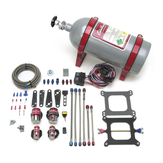
Page 8: 2-Stage Performer Rpm Nitrous System Bill Of Materials
3AN 12” Steel Braided Hose, Blue 1 ea 4AN to 3AN 8” Steel Braided Hose, Red 1 ea 3AN 8” Steel Braided Hose, Red Not Shown Above Bottle and Bottle Brackets Various Included Jets Page 8 of 28 Rev. 03/04 Catalog #70003 & #70004... -
Page 9: Nitrous System Installation
Device (PRD) Bottle Safety Information 1. Do not attempt to remove the bottle valve. Please return your bottle to Edelbrock if service is required to the siphon tube inside the bottle or the bottle valve itself. 2. Never heat the outside of your nitrous bottle with an open flame like that of a torch. -
Page 10: Bottle Orientation
An Edelbrock nitrous bottle cannot be mounted upside-down. Edelbrock does not offer a non-siphon tube bottle for automotive use. If the bottle must be mounted parallel to the axles of the vehicle (sideways), the label must be angled at approximately 45 degrees toward the front of the vehicle. -
Page 11: Nitrous Bottle Installation
Do not attempt to install the bottle in the bracket without the rubber insulator. The bottle hoop on the bracket is designed to include the thickness of the insulator. Page 11 of 28 Rev. 03/04 Catalog #70003 & #70004... -
Page 12: Nitrous Feed Line Mounting
Teflon paste in the outlet port of the Performer RPM Fuel Solenoid being careful not to over tighten. 8. Remove the solenoid from the bench vise or whatever is holding it. ©2004 Edelbrock Corporation Brochure No. 63-0190 - DC/mc Page 12 of 28 Rev. 03/04 Catalog #70003 & #70004... -
Page 13: Mounting Your Solenoids
The Performer solenoid brackets can be bent and shaped in the same fashion as the Performer RPM brackets pictured here. ©2004 Edelbrock Corporation Brochure No. 63-0190 - DC/mc Page 13 of 28 Rev. 03/04 Catalog #70003 & #70004... -
Page 14: Fuel And Nitrous Y-Fittings Installation
Solenoid. Connect the remaining end of this hose to the 4AN blue Y-Fitting. 8. Connect the main feed line hose to the remaining 4AN fitting of the 4AN blue Y-Fitting. ©2004 Edelbrock Corporation Brochure No. 63-0190 - DC/mc Page 14 of 28 Rev. 03/04 Catalog #70003 & #70004... -
Page 15: Nitrous Injection Plate Installation
Every precaution has been taken to ensure the cleanliness of our components during the assembly of your Edelbrock Nitrous System. However, because of the importance of the jets and the calibration, extra care should be taken before you install your jets. Wash them thoroughly with brake cleaner or another non oil based cleaner, before installing them into the plate. -
Page 16: Electrical System Installation
Important: The wiring hardware and instructions included with this kit are intended for 12-volt electrical systems only. Before attempting to wire your Edelbrock Performer nitrous oxide system, examine and follow the wiring diagram on the following page. Please call the Edelbrock Technical department with any questions concerning electrical wiring. -
Page 18: Nitrous Electrical System Installation Procedures
The wire harness attached to the relay and fuse holder includes 8 feet of color-coded wires to make the electrical system installation for your Edelbrock Nitrous System as easy as possible. We recommend not cutting any lengths of wires from the wire harness or complete the wiring of the nitrous system until all of the mechanical components are securely mounted in their permanent locations. -
Page 19: Arming Switch And Installation
It also is of a universal length and can be attached to several positions on and around the throttle body. ©2004 Edelbrock Corporation Brochure No. 63-0190 - DC/mc Page 19 of 28 Rev. 03/04 Catalog #70003 & #70004... -
Page 20: Final Electrical Installation Recommendations
2. Double Check the wires that lead from the microswitch to ensure that they do not interfere with the operation of the throttle body linkage. You are now ready to hook up your battery and prepare your vehicle to run. ©2004 Edelbrock Corporation Brochure No. 63-0190 - DC/mc This Page 20 of 28 Rev. 03/04 Catalog #70003 & #70004... -
Page 21: Before You Run Your Vehicle Using Your Edelbrock Nitrous System
Before You Run Your Vehicle Using Your Edelbrock Nitrous System You have just completed the installation of your Edelbrock Nitrous System. It is time to perform some basic system checks to ensure all of the work you have done is correct and ready to operate properly. The following procedure is designed to... -
Page 22: Baseline Tuning Suggestions
5.1 Nitrous Bottle Pressure...Always keep your bottle pressure between 900 and 950 psi. Yes, there are racers that use different pressures, but the testing we did here at Edelbrock to ensure the jetting maps within this manual are correct, was done in this pressure range. Use any higher pressure than 950 psi and you will be lean. Use any pressures below 900 psi and you will be rich. -
Page 23: Ignition Timing And Nitrous
5. Use all of your senses to determine how your vehicle is operating. Listen for detonation, watch your gauges, smell for strange odors, etc. ©2004 Edelbrock Corporation Brochure No. 63-0190 - DC/mc 38 degrees “total” 2 degrees “retard” 2 degrees “retard” 34 degrees “total” Testing Checklist Page 23 of 28 Rev. 03/04 Catalog #70003 & #70004... -
Page 24: Solenoid Inspection And Maintenance
Remove any contaminants that may be present. Make sure solenoid body is clean, dry and free of oils before assembly. 10. Replace the O-Ring, plunger and piston spring. 11. Re-assemble solenoid by reversing disassembly procedure. ©2004 Edelbrock Corporation Brochure No. 63-0190 - DC/mc Page 24 of 28 Rev. 03/04 Catalog #70003 & #70004... - Page 25 Troubleshooting Your Edelbrock Nitrous System How to use our Troubleshooting Flowchart: The troubleshooting of a nitrous system is basic and straightforward. The symptom chart is divided by symptom, cause and action required. Determine your problem (symptom), identify the potential problem (cause) and correct the problem (action required).
- Page 26 10. Malfunctioning nitrous solenoid. a. Inspect solenoid wiring. See “Electrical System Installation” section. Repair wiring. b. Inspect solenoid. See symptom #2. Rebuild/replace solenoid. ©2004 Edelbrock Corporation Brochure No. 63-0190 - DC/mc Page 26 of 28 Rev. 03/04 Catalog #70003 & #70004...
- Page 27 2. Weak ignition/ignition component failure. a. Inspect ignition components. Replace worn components. ii. Upgrade ignition system to high performance high load capable ignition components. ©2004 Edelbrock Corporation Brochure No. 63-0190 - DC/mc Page 27 of 28 Rev. 03/04 Catalog #70003 & #70004...
- Page 28 Maintain 80 to 85 degrees of bottle surface temperature. c. Check bottle valve. Open valve fully d. Check bottle orientation. Mount bottle properly. ©2004 Edelbrock Corporation Brochure No. 63-0190 - DC/mc Page 28 of 28 Rev. 03/04 Catalog #70003 & #70004...
Need help?
Do you have a question about the 70003 and is the answer not in the manual?
Questions and answers