Table of Contents
Advertisement
Quick Links
Download this manual
See also:
User Manual
Advertisement
Table of Contents

Related Manuals for Sena Parani-SD100


Summary of Contents for Sena Parani-SD100
-
Page 1: User Guide
Parani-SD100/200 User Guide Version 1.0.0 2006-07-22... - Page 2 This device is not approved for life-support or medical systems. Changes or modifications to this device not explicitly approved by Sena Technologies will void the user's authority to operate this device.
- Page 3 Contents 1. Introduction 1.1. Overview ...........................6 1.2. Package Check List........................6 1.3. Product Specification........................7 2. Getting Started 2.1. Panel Layout ..........................8 2.2. Connecting the Hardware ......................9 2.2.1. Connecting Power to Parani-SD ..................9 2.2.2. Connecting Device to Parani-SD ...................10 2.2.3. Attaching Batter Pack to Parani-SD200.................10 3.
- Page 4 B.3.2. AT&F ..........................29 B.3.3. AT ..........................29 B.3.4. AT+UARTCONFIG,Baudrate,Parity,Stopbit ..............29 B.3.5. AT+USEDIP? .......................30 B.3.6. AT+BTINFO? .......................30 B.3.7. AT+BTINQ? .........................30 B.3.8. AT+BTLAST? .......................30 B.3.9. AT+BTVER? ........................31 B.3.10. AT+BTRSSI,n ......................31 B.3.11. AT+BTMODE,n ......................31 B.3.12. +++ ..........................31 B.3.13. AT+SETESC,nn ......................32 B.3.14. ATO ..........................32 B.3.15. AT+BTCANCEL ......................32 B.3.16.
- Page 5 D.2.2 AT Response ........................42 D.3 Transmission Delay ........................43 D.3.1 RF Processing Delay......................43 D.3.2 RF Transmission Environment ..................43...
-
Page 6: Introduction
Parani-SD provides several models with different communication ranges from 30m (Parani-SD200) up to 100m (Parani-SD100) for user’s various applications. In terms of noise, Parani-SD delivers better quality of communication than standard RS232 cables. Parani-SD has the most compact design of the same kind devices and can be placed conveniently into any devices or equipments. -
Page 7: Product Specification
1.3. Product Specification SD100 SD200 Serial Interface One male DB9 serial port for data communication Serial speeds 1200bps to 230400bps Flow Control: None, Hardware RTS/CTS Signals: Rx, Tx, RTS, CTS, DTR, DSR, GND Bluetooth v1.2 Bluetooth Interface Protocol: RFCOMM, L2CAP, SDP Profile: General Access Profile, Serial Port Profile Class 1 Class 2... -
Page 8: Getting Started
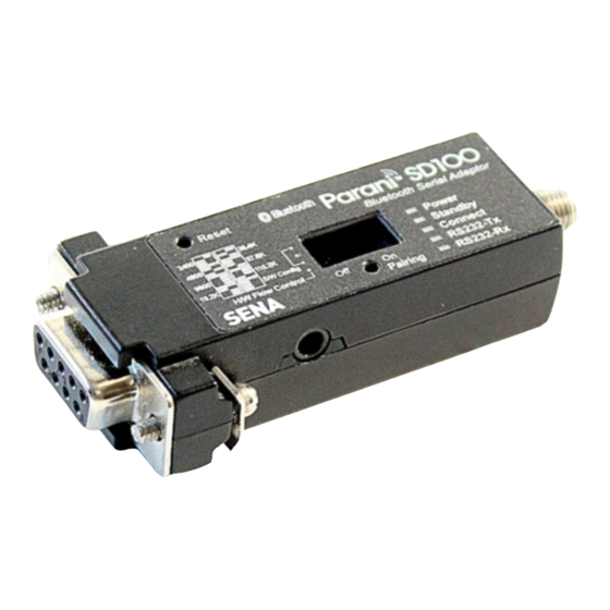
- Terminal emulation program running on the PC - One battery pack and two ‘AA’ batteries (optional accessory for SD200 only) 2.1. Panel Layout This section describes the panel layout of the Parani-SD. Figure 2-1 The panel layout of Parani-SD100... -
Page 9: Connecting The Hardware
Figure 2-2 The panel layout of Parani-SD200 2.2. Connecting the Hardware This section describes how to connect the Parani-SD Series to the serial device for initial testing. - Connect a power source to the Parani-SD Series. - Connect the Parani-SD Series to a serial device. 2.2.1. -
Page 10: Connecting Device To Parani-Sd
2.2.2. Connecting Device to Parani-SD Connect the serial device to the Parani-SD Series as shown below. Figure 2-4 Connecting a Serial Device to Parani-SD 2.2.3. Attaching Batter Pack to Parani-SD200 The Parani-SD200 supports battery pack that can carry two AA batteries as an optional accessory. Users can use both general type batteries or rechargeable ones. -
Page 11: Configuration
3. Configuration 3.1. Operation Modes In addition to the serial port configurations such as bit/second, data bit, parity, stop bit, flow control, Parani-SD has some configurations for Bluetooth. For getting the most out of Parani-SD, user should understand the following Bluetooth connection schemes. A Bluetooth device can play a role as a master or slave. -
Page 12: Led Indicators
3.2. LED Indicators RS232-Tx and RS232-Rx LED are blinking accordingly when data is transmitted. For small data transmission, it may be hard to recognize the quick blinking. Table 3-2 The Parani-SD LED Indicators Indicator Power LED Standby LED Connect LED ┏━━━━━... -
Page 13: Reset To Factory Defaults
For large data transmission, use of hardware flow control is highly recommended. 3.3.3. Reset to Factory Defaults To turn back all the configurations to its factory settings, press the reset button depicted in Fig. 1-3. Press the reset button with a narrow pointed tool like paper clip longer than 1 second. Reset works only when power is on. -
Page 14: Software And Utility
Master Connect LED is lit in green green 3.3.6. Software and Utility This configuration software and utility for firmware update comes with the product, which also can be downloaded from http://www.sena.com Table 3-7 Configuration Software Software Purpose Operating System ParaniWIN... - Page 15 Figure 3-2 Serial Port Setting Set each option properly and click [Confirm]. If the settings are different from the host computer, error message will pop up. If the Parani-SD is in the status of connection, warning message will pop up. Then the current connection can be cancelled by [Disconnect] button on the main window.
- Page 16 Figure 3-4 Main Window Figure 3-5 Information Window Serial port settings can be changed by <Start Configuration> and <ParaniWIN Configuration> of ParaniWIN in the menu bar at upper left corner of the window without re-running the ParaniWIN program. Figure 3-6 Menu Bar at Upper Left corner of ParaniWIN The icons in the left side window come to the corresponding windows.
- Page 17 To prevent this, user can set the Command response to ON or OFF. For Parani-SD100/200, hardware flow control can be configured only by dip switch. Thus H/W Flow Control option will not work in this case.
- Page 18 Figure 3-8 Connect(out) Window Click [Search] button to search nearby Bluetooth devices. The maximum number of devices to be searched can be controlled. Select one of the devices searched and click [Connect] button. The selected Bluetooth device must be in Page scan mode. Click [Disconnect] button to cancel the connection normally.
- Page 19 Figure 3-9 Sensitivity Test The sensitivity test shows LInkQuality and RSSI values. The sensitivity is fine, If the LinkQuality is closer to 255 and RSSI is closer to 0. In general, the sensitivity is the best when the distance is 10 meters.
- Page 20 Figure 3-10 Connection(in) Window If the Connection Wizard icon is clicked, an easy pairing menu to use appears as follows: Figure 3-11 Connection Wizard Window...
-
Page 21: Paraniupdater
3.3.8. ParaniUpdater Parani-SD support firmware update. You can download new firmwares of Parani-SD at http://www.sena.com. With ParaniUpdater, you can update firmware of Parani-SD by selecting the firmware image file and pushing Start button. * Note: DO NOT power off Parani-SD while the firmware update is progressing. It may damage the firmware seriously. - Page 22 Attach Parani-SD to serial port of host computer and power on. Check Connect LED and Standby LED. Their status may be as follows: Table 3-8 Connect LED and Standby LED status Connect LED Standby LED Meanings Connected to somewhere Blinking Connecting to somewhere or waiting for incoming connection.
-
Page 23: Approval Information
4. Approval Information 4.1. FCC 4.1.1. FCC Compliance Statement This device complies with part 15 of the FCC Rules. Operation is subject to the following two conditions: (1) This device may not cause harmful interference, and (2) This device must accept any interference received, Including interference that may cause undesired operation 4.1.2. -
Page 24: Rf Information
5. RF Information 5.1. Radio Frequency Range 2.402~2.480GHz 5.2. Number of Frequency Channel 79 channels 5.3. Transmission Method FHSS(Frequency Hopping Spread Spectrum) 5.4. Modulation Method GFSK(Gaussian-filtered Frequency Shift Keying) 5.5. Radio Output Power Products Radio Output Power SD100 +18dBm SD200 +18dBm 5.6. -
Page 25: Appendix A: Connections
Appendix A: Connections A.1. Serial Port Pin Outs Parani-SD is a DCE device compatible with RS232 standard, having DB9 female interface. Figure A-1 Pin layout of the DB-9 female connector Table A-1. Pin assignment of the DB-9 female connector Pin # Signal Direction Description... -
Page 26: A.2.1. To Host With Dte Interface
A.2.1. To Host with DTE Interface A.2.2. To Host with DCE Interface... -
Page 27: Appendix B: At Commands
Appendix B: AT Commands B.1. Terminology B.1.1. AT Command AT command set is the d e facto standard l anguage for controlling m odems . The AT command set was developed by H ayes and is recognized by virtually all p ersonal computer modems. -
Page 28: B.1.5. Symbols
B.1.5. Symbols The symbols are used for the description of command syntax as follows: Symbols Meaning ASCII Code Carriage return 0x0D Line feed 0x0A Carriage return + Line feed Bluetooth device address N or m One digit decimal number Timeout in seconds B.2. -
Page 29: B.3. Command Description
B.3. Command Description B.3.1. ATZ SD Response Purpose Software Reset Description This is the same effect as power off and on. This command disconnects Bluetooth device, and stops ongoing task. After rebooting, the status is decided by the preset operation mode. Some AT commands need ATZ to take effect. -
Page 30: B.3.5. At+Usedip
Mode=MODE0/MODE1/MODE2/MODE3 Status=STANDBY/PENDING/CONNECT Auth=0/1 (Authentication is not activated when 0) Encrypt=0/1 (Encryption is not activated when 0) FlowControl=HWFC/NoFC Reference AT+BTNAME, AT+BTMODE, AT+BTSEC, ATS14? Example 000B530011FF,SENA,MODE0,PENDING,1,1,HWFC B.3.7. AT+BTINQ? SD Response 112233445566,FriendlyName,CoD 112233445566,FriendlyName,CoD 112233445566,FriendlyName,CoD Purpose Search Bluetooth devices nearby Description The Bluetooth devices in Inquiry scan mode nearby are displayed with their BD addresses, Device names, and Class of device. -
Page 31: B.3.9. At+Btver
Reference AT+BTSCAN, ATD, AT+BTINFO?, AT+BTINQ? B.3.9. AT+BTVER? SD Response SD100v1.0.0 Purpose Display device firmware version Description Display device firmware version Reference AT+BTINFO? B.3.10. AT+BTRSSI,n SD Response 0,255,0,0 (repeatedly) Purpose Test sensitivity Parameters n=0: Start sensitivity test n=1: Stop sensitivity test Description When Bluetooth connection is established, you can use this command in Stanby status. -
Page 32: B.3.13. At+Setesc,Nn
SD Response Purpose Convert the operation status of ‘Connect’ to ‘Standby’ Description In ‘Connect’ status, data from host is transmitted to the other side Bluetooth device, and any AT command is not accepted but this command, which is not echoed on the screen. When Parani-SD encounters a character ‘+’... -
Page 33: B.3.17. At+Btscan,N,To
Description This allows the inquiry and connection from the other Bluetooth devices. The operation status will be in ‘Pending’ after this command. When connection is made and released, the operation status is back to ‘Pending’. To convert the operation status to ‘Standby’ AT+BTCANCEL must be used. -
Page 34: B.3.20. Atd112233445566
SD Response CONNECT 112233445566 ERROR Purpose Connect to the last connected Bluetooth device Description Parani-SD saves the BD address of the Bluetooth device most recently connected. ATD can make connection to it without input its BD address. If it fails to make connection, SD response is ‘ERROR’. Reference AT+BTINQ?, AT+BTSCAN B.3.20. -
Page 35: B.3.23. At+Btsd
Example AT+BTKEY=”apple” B.3.23. AT+BTSD? SD Response 112233445566 Purpose Display the list of Bluetooth devices sharing the pin code Description Once a connection is made with pin code, Parani-SD saves the Bluetooth device with its link key generated by pin code. The connection to a device listed in Parani-SD can be made automatically without authentication process. -
Page 36: B.3.27. At+Btname=$String
B.3.27. AT+BTNAME=$string SD Response Purpose Change device name Parameters $string= New device name (Default=”PSDv3b-445566”) Description Parani-SD can have a user friendly name to identify easily. The name allows 30 alpha- numeric characters maximum. Reference AT+BTINFO?, AT+BTINQ? Example AT+BTNAME=”My-Parani-SD” B.3.28. AT+BTLPM,n SD Response Purpose Set low power mode... -
Page 37: B.3.32. Atsnn=Mm
Purpose Display a given S-register Parameters nn= Address of S-register Description A specific S-register is displayed. Reference AT&V B.3.32. ATSnn=mm SD Response Purpose Change S-register value Parameters nn= Address of S-register mm= New value of S-register Description Some S-registers are optimized for the overall performance and protected from an arbitrary change by user. - Page 38 ◎ AT+BTMODEn ◎ AT+BTNAME=”Name” ◎ AT+BTKEY=”nnnn” ○ AT+BTINFO? ◎ AT+BTLPM,n ○ ○ AT+BTSD? ◎ AT+BTCSD ◎ AT+BTFP,n ◎ AT+UARTCONFIG,b,p,s ○ ○ AT+USEDIP? ○ ○ AT+BTVER? ◎ ◎ AT+DFU ● AT+BTRSSI,n ◎ Valid only when Parani-SD is not connected to other Bluetooth device. ●...
-
Page 39: Appendix C: S-Register
Appendix C: S-Register S-registers contain 46 parameters of Parani-SD. These are stored in flash memory and sustained the values unless hardware reset is executed. The value of S-register can be accessed and changed with ATS command by user. Some S-registers not shown below are set to maximize the performance of Parani-SD. - Page 40 C.5. S6: Enable Low Power Mode (default 0) S10=0, deactivate Low Power Mode. S10=1, activate Low Power Mode. This value decides whether SD works in Low Power Mode or not. When this value is 0, SD works only in active power mode. When SD works in Low Power mode, delay in transferring data may occur. C.6.
-
Page 41: C.17. S46: Bd Address Of Last Connected Device
S22=3, page/inquiry scan C.12. S24: Maximum Number of Inquiry Result (default 10) The maximum number of inquiry list can be controlled. This value is up to C.13. S28: Escape Sequence Character (default 43) The decimal number of the ASCII code of escape sequence character can be controlled. The initial value is 43, the ASCII code of ‘+’. -
Page 42: Appendix D: Trouble Shooting
Appendix D: Trouble Shooting D.1 No Data Transmission D.1.1 COM Port Settings Check whether the Baud rate of Parani-SD is same as that of its host equipment. You can know the Baud Rare if you check the dipswitch. If it is Atcommand mode, you can initialize Baud rate to 9600 by pressing Reset Button. -
Page 43: D.3 Transmission Delay
The messages of AT response may affect the function of host system. Set ATS10=0 not to send SD response to host system and try again. Refer Appendix B. for details. D.3 Transmission Delay D.3.1 RF Processing Delay It takes 30msec approximately for a Parani-SD to complete the data transmission to the other side Bluetooth device. -
Page 44: Fcc Compliance Statement
FCC CONCERNS FCC Compliance Statement This device complies with part 15 of the FCC Rules. Operation is subject to the following two conditions: (1) This device may not cause harmful interference, and (2) This device must accept any interference received, including interference that may cause undesired operation.
Need help?
Do you have a question about the Parani-SD100 and is the answer not in the manual?
Questions and answers