
Related Manuals for Caen SY 2527


Summary of Contents for Caen SY 2527
- Page 1 User's Manual Revision n. 0 27 November 2000 MOD. SY 2527 UNIVERSAL MULTICHANNEL POWER SUPPLY SYSTEM USER’S MANUAL NPO: 00103/97:2527y.MUTx/00...
- Page 2 Document type: Title: Revision date: Revision: User's Manual (MUT) Mod. SY2527, Universal Multichannel Power Supply System 27/11/2000 TABLE OF CONTENTS ABOUT THIS MANUAL ........................7 ..........................8 RGANISATION ........................... 9 ONVENTIONS 1.2.1 Safety rules ..........................9 1.2.2 Electrical signal specifications ....................9 GENERAL DESCRIPTION OF THE SYSTEM ................
- Page 3 RS232 ........................... 36 INTERFACE (TCP/IP ) ..................37 THERNET INTERFACE PROTOCOL 6.2.1 Configuring the SY 2527 System for network connection ............37 6.2.2 Configuring the host PC......................37 6.2.3 Verifying connection ....................... 38 H.S. CAENET ....................... 39 INTERFACE OPERATING MODES......................... 40 .........................
- Page 4 Document type: Title: Revision date: Revision: User's Manual (MUT) Mod. SY2527, Universal Multichannel Power Supply System 27/11/2000 7.1.12 The MAIN Menu: Logout ......................55 7.1.13 The GROUPS Menu and relevant commands ................55 7.1.14 The VIEW Menu and relevant commands ................58 7.1.15 The UTILITY Menu: Kill ......................
-
Page 5: List Of Figures
....................... 35 EMOTE CONNECTORS . 6.1 – RS232 ....................36 CONNECTOR PIN ASSIGNMENT . 6.2 - T " " SY 2527 ............38 HE RESULT OF A SUCCESSFUL PING TO THE SYSTEM . 7.1 – S ....................... 40 TANDALONE PERATION . -
Page 6: List Of Tables
Document type: Title: Revision date: Revision: User's Manual (MUT) Mod. SY2527, Universal Multichannel Power Supply System 27/11/2000 LIST OF TABLES 2.1 - T SY2527 ..........15 ABLE ECHNICAL SPECIFICATIONS OF THE MAINFRAME GENERAL 2.2 - T SY2527 .. 16 ABLE ECHNICAL SPECIFICATIONS OF THE MAINFRAME FRONT AND REAR PANEL COMPONENTS... -
Page 7: About This Manual
Document type: Title: Revision date: Revision: User's Manual (MUT) Mod. SY2527, Universal Multichannel Power Supply System 27/11/2000 1. About this manual The purpose of this guide is to illustrate: • the several parameters and commands available for the control and status monitoring of the SY2527 Universal Multichannel Power Supply System and of the board channels, •... - Page 8 Document type: Title: Revision date: Revision: User's Manual (MUT) Mod. SY2527, Universal Multichannel Power Supply System 27/11/2000 Organisation This guide is organised as follows: Chapter 1 – About this manual: it shortly describes the objectives and organisation of this guide; Chapter 2 –...
-
Page 9: Electrical Signal Specifications
Document type: Title: Revision date: Revision: User's Manual (MUT) Mod. SY2527, Universal Multichannel Power Supply System 27/11/2000 Conventions The conventions adopted all through the manual are shortly listed in the following. 1.2.1 Safety rules The user is requested to pay particular attention to the parts of the document containing the following terms: WARNING: Warning statements identify conditions or practices that could result in injury or... -
Page 10: General Description Of The System
Hardware Installation Guide. Overview The SY2527 system is the small scale experiment version of the latest CAEN UNIVERSAL MULTICHANNEL POWER SUPPLY SYSTEM. This system outlines a completely new approach to power generation and distribution by allowing to house, in the same mainframe, a wide range of boards with different functions, such as High/Low Voltage boards, generic I/O boards (temperature, pressure monitors, etc.) and branch... - Page 11 ‘intelligent’ SY2527 system able to drive other ‘non systems, i.e. systems without CPU (to be implemented). The connections among the systems constituting the cluster are realised through a new CAEN interface, the Local Net. The extreme flexibility of the system, which allows to house indifferently, inside the...
- Page 12 Document type: Title: Revision date: Revision: User's Manual (MUT) Mod. SY2527, Universal Multichannel Power Supply System 27/11/2000 Short Functional description A block diagram of the SY2527 system is shown in Fig. 2.2, p.14. A single crate can host up to 6 Channel Boards, which can be chosen in a wide range of plug-in boards, from standard HV/LV boards and floating boards to generic I/O boards monitoring external parameters or branch controllers.
- Page 13 Document type: Title: Revision date: Revision: User's Manual (MUT) Mod. SY2527, Universal Multichannel Power Supply System 27/11/2000 2) TRIP = finite value (TRIP mode) In this case, the channel behaves as in the constant CURRENT mode for a time equal to the finite value set as TRIP parameter, and then it is switched off according to the selected Power-Down option (Kill/Ramp-Down).
- Page 14 Document type: Title: Revision date: Revision: User's Manual (MUT) Mod. SY2527, Universal Multichannel Power Supply System 27/11/2000 HV Board HV Board HV Board Slot 0 Slot 1 Slot 5 Board Backplane I/O Board 16-bit Interface Bus Backplane Keyboard Controller of: Keyboard, Compact Switch, LCD contrast Mouse...
- Page 15 Document type: Title: Revision date: Revision: User's Manual (MUT) Mod. SY2527, Universal Multichannel Power Supply System 27/11/2000 Technical specification tables Table 2.1 - Technical specifications of the SY2527 mainframe: general - 19"-wide, 4U-high Euro-mechanics rack; Packaging - Depth: 770 mm. Mainframe (*): 19 kg Weight Monophase: 88÷264 V a.c., 48÷64 Hz;...
- Page 16 Document type: Title: Revision date: Revision: User's Manual (MUT) Mod. SY2527, Universal Multichannel Power Supply System 27/11/2000 Table 2.2 - Technical specifications of the SY2527 mainframe: front and rear panel components (refer to the figure in Appendix A) − GEN, red LED, lights up as GENERAL STATUS signal, corresponding to a logic combination (defined by the user) of OVC, UNV, OVV, TRIP, is TRUE;...
- Page 17 Document type: Title: Revision date: Revision: User's Manual (MUT) Mod. SY2527, Universal Multichannel Power Supply System 27/11/2000 Table 2.3 - Technical specifications of the SY2527 mainframe: input and output signals (refer to the figure in Appendix A) Std. NIM/TTL; 00-type LEMO connector. VSEL: Function: channel voltage selection.
-
Page 18: Safety Information And Operation Requirements
Document type: Title: Revision date: Revision: User's Manual (MUT) Mod. SY2527, Universal Multichannel Power Supply System 27/11/2000 3. Safety information and operation requirements This section contains the fundamental safety rules for the installation and operation of the SY2527 system. Read thoroughly this section before starting any procedure of installation or operation of the product. -
Page 19: Product Damage Precautions
Document type: Title: Revision date: Revision: User's Manual (MUT) Mod. SY2527, Universal Multichannel Power Supply System 27/11/2000 3.1.2 Product Damage Precautions Use Proper Power Source. Do not operate this product from a power source that applies more than the voltage specified. -
Page 20: Peration R Equirements
Document type: Title: Revision date: Revision: User's Manual (MUT) Mod. SY2527, Universal Multichannel Power Supply System 27/11/2000 General Operation Requirements Before operation, check the following requirements: Operating temperature: 5÷40°C (dry atmosphere) Max. length of cables: according to cable specifications NPO: Filename: Number of pages: Page:... -
Page 21: System And Channel Control
Document type: Title: Revision date: Revision: User's Manual (MUT) Mod. SY2527, Universal Multichannel Power Supply System 27/11/2000 4. System and channel control Introduction All the parameters' readout or modification requests coming from different sources (local control devices, video terminal, H. S. CAENET controller, etc.) are handled by the CPU of the system. -
Page 22: Local/Remote Power-On
Document type: Title: Revision date: Revision: User's Manual (MUT) Mod. SY2527, Universal Multichannel Power Supply System 27/11/2000 4.2.1 NIM / TTL standard selection A two-position switch, located on the front panel, allows to select the standard for almost all the control output signals. Nominally, the switch position affects the standard of the OVC, UNV, OVV, CH-ON, RST FLAG, CHK PASSED, TRIP and GEN signals. -
Page 23: Vsel Command
Document type: Title: Revision date: Revision: User's Manual (MUT) Mod. SY2527, Universal Multichannel Power Supply System 27/11/2000 according to the level of the VSEL input; refer to § 4.2.4, p.23) with the rate determined by the Ramp-Up parameter. The channels which are OFF will remain OFF. If the channels are disabled via the switch (DISABLE position), the output voltages of the channels which are ON drop to 0 at the rate determined by the Ramp-Down parameters. -
Page 24: Interlock Command
Document type: Title: Revision date: Revision: User's Manual (MUT) Mod. SY2527, Universal Multichannel Power Supply System 27/11/2000 RESET signal CPU RESET BOARDS' RESET starts up RCPU RESET time 100÷200 ms 900 ms Fig. 4.1 – RESET timing • If the RESET signal is longer than T =100÷200 ms (RESET LED red), only RCPU the CPU is reset and the whole system resumes its operation from the... -
Page 25: Hv Sync
Document type: Title: Revision date: Revision: User's Manual (MUT) Mod. SY2527, Universal Multichannel Power Supply System 27/11/2000 In order to turn the channels on again, the user must remove the INTERLOCK condition. Any attempt to turn the channels on without removing the INTERLOCK condition will result unsuccessful. -
Page 26: Under Voltage
Document type: Title: Revision date: Revision: User's Manual (MUT) Mod. SY2527, Universal Multichannel Power Supply System 27/11/2000 to the selected Power-Down option (KILL/RAMP). If the Kill option is selected, the channel will be switched off at the maximum rate available. If the Ramp option is selected, the voltage will drop to zero at a rate determined by the value of the Ramp parameter programmed for that channel. -
Page 27: Ch-On
Document type: Title: Revision date: Revision: User's Manual (MUT) Mod. SY2527, Universal Multichannel Power Supply System 27/11/2000 At normal operation, this signal is True and the relevant green LED is ON. This output signal becomes false either as the Fan failure LED is alight or as the Power failure LED is alight. -
Page 28: C Hannel P Arameters
HV Power Supply Board (HV PWS Board, Mod. A1832). Although the number and type of parameters associated to each channel depend on the board's model, the following includes almost all parameters you can find when using a CAEN PWS Board. 4.4.1 CHANNEL NUMBER (CH #) CH # is the physical name of the channel which corresponds to its complete address (refer to Fig. -
Page 29: Channel Name (Channel)
Document type: Title: Revision date: Revision: User's Manual (MUT) Mod. SY2527, Universal Multichannel Power Supply System 27/11/2000 4.4.2 CHANNEL NAME (CHANNEL) It is the symbolic name of the channel and, up to now, can be modified only via Remote Control. It may be up to 11 characters long and may contain any of the following characters: "0..9", "A..Z", "a..z", "#", "&", "%", "$", "*", "_"... -
Page 30: V1Set
Document type: Title: Revision date: Revision: User's Manual (MUT) Mod. SY2527, Universal Multichannel Power Supply System 27/11/2000 4.4.7 V1SET It is the second of the two allowed Voltage programmable values (in absolute value). It is active when the VSEL input signal is TRUE. It can be programmed either via Local or Remote Control. -
Page 31: Imon
Document type: Title: Revision date: Revision: User's Manual (MUT) Mod. SY2527, Universal Multichannel Power Supply System 27/11/2000 4.4.12 IMON Current Monitored value. It can be monitored either via Local or Remote Control. 4.4.13 TRIP It is the maximum time an Overcurrent condition is allowed to last. If an Overcurrent condition lasts for more than the programmed value, the System will react in the following ways: If Trip = 1000:... -
Page 32: Power-On (Pon)
Document type: Title: Revision date: Revision: User's Manual (MUT) Mod. SY2527, Universal Multichannel Power Supply System 27/11/2000 As the channel is turned on, the output drifts from 0 to the programmed value (V0SET or V1SET according to the VSEL signal level) at the programmed rate (RAMP-UP parameter). -
Page 33: B Oard Status
Document type: Title: Revision date: Revision: User's Manual (MUT) Mod. SY2527, Universal Multichannel Power Supply System 27/11/2000 Board status Several messages on the board status are displayed by the User Software Interface. In particular, in the Channels Window there is a column displaying the temperature detected on the PCB of the board (TEMP column) and another one displaying various messages on the board status. -
Page 34: System Power-On
Document type: Title: Revision date: Revision: User's Manual (MUT) Mod. SY2527, Universal Multichannel Power Supply System 27/11/2000 5. System Power-On The Power-ON of the system can be performed either locally or remotely, as described in the following subsections. Preliminary check Before powering the system, check that: 1. -
Page 35: Remote Power-On
Document type: Title: Revision date: Revision: User's Manual (MUT) Mod. SY2527, Universal Multichannel Power Supply System 27/11/2000 Remote Power-On To power-On the system remotely follow this procedure: Turn on the MAIN switch located on the rear panel of the crate: the MAIN LED (orange), located on the front panel (refer to Front Panel figure in the Appendix), lights up. -
Page 36: Configuring The Interfaces
Document type: Title: Revision date: Revision: User's Manual (MUT) Mod. SY2527, Universal Multichannel Power Supply System 27/11/2000 6. Configuring the interfaces RS232 interface The RS232 interface provided with the system is a 9-pin D-type male RS232 serial port and can be used to interface a VT100 terminal or an external standard IBM Personal Computer running a terminal emulator program (Remote operation via terminal using the RS232 interface, see §... -
Page 37: E Thernet Interface (Tcp/Ip Protocol )
Mask must be assigned by the local Network Administrator to the SY 2527 System. The default settings of the TCP/IP protocol for the SY 2527 System are as listed in Table 6.2: the default settings correspond to the network connection inactive. -
Page 38: Verifying Connection
< SY 2527 IP address > where < SY 2527 IP address > is the IP address assigned to the SY 2527 system. The dialog box below illustrates the result of a successful "ping " with the Ethernet connection shown established. -
Page 39: H.s. Caenet Interface
Document type: Title: Revision date: Revision: User's Manual (MUT) Mod. SY2527, Universal Multichannel Power Supply System 27/11/2000 H.S. CAENET interface The H.S. CAENET interface provided with the system allows control via another SY2527 crate connected to an external standard Personal Computer via RS232 interface and running a terminal emulator program (Remote operation via terminal using the H.S. -
Page 40: Operating Modes
Document type: Title: Revision date: Revision: User's Manual (MUT) Mod. SY2527, Universal Multichannel Power Supply System 27/11/2000 7. Operating modes NOTICE! PRESENTLY, THE SYSTEM CAN BE USED IN: • • STANDALONE OPERATION, • • REMOTE OPERATION VIA TERMINAL BY USING EITHER THE RS232 OR TELNET CONNECTION. -
Page 41: Local Control Devices
Document type: Title: Revision date: Revision: User's Manual (MUT) Mod. SY2527, Universal Multichannel Power Supply System 27/11/2000 The keyboard can be plugged into one of the two PS/2 connectors located on the front panel (the PS/2 connector in the lowest position), while the standard VGA monitor can be connected to the VGA port placed on the front panel. -
Page 42: Software Version
Document type: Title: Revision date: Revision: User's Manual (MUT) Mod. SY2527, Universal Multichannel Power Supply System 27/11/2000 Table 7.1 – Local control commands and external keyboard commands Local control commands Keyboard commands CMD keypad key TAB key DEL keypad key DELETE key ACK keypad key ENTER key... -
Page 43: Menu Structure
Document type: Title: Revision date: Revision: User's Manual (MUT) Mod. SY2527, Universal Multichannel Power Supply System 27/11/2000 7.1.3 Menu Structure At Power On in standalone configuration the User Interface Software will show a Welcome Screen. By pressing any key the Login Window will be shown and, after the Login procedures, the Start Up Window will appear. -
Page 44: Welcome Window
Document type: Title: Revision date: Revision: User's Manual (MUT) Mod. SY2527, Universal Multichannel Power Supply System 27/11/2000 7.1.4 Welcome Window The Welcome Window which appears as the system is powered On is shown in Fig. 7.3. Fig. 7.3 – Welcome Screen in Standalone Operation 7.1.5 Login Window The Login Window is shown in Fig. -
Page 45: Start Up Window
Document type: Title: Revision date: Revision: User's Manual (MUT) Mod. SY2527, Universal Multichannel Power Supply System 27/11/2000 Fig. 7.4 – Login Window 7.1.6 Start Up Window The Start Up Window is shown in Fig. 7.5. The Menu Bar at the top of the window allows to enter all the other windows available, according to the structure shown in Fig. - Page 46 Document type: Title: Revision date: Revision: User's Manual (MUT) Mod. SY2527, Universal Multichannel Power Supply System 27/11/2000 • Status, which allows to define the conditions to assert the GEN output signal; • Trip Handling, , which allows a sophisticated handling of trip conditions; •...
- Page 47 Document type: Title: Revision date: Revision: User's Manual (MUT) Mod. SY2527, Universal Multichannel Power Supply System 27/11/2000 7.1.7 Menu: About The About command, entered from the – menu that is the first on the left in the Menu Bar, displays the About Window (Fig. 7.6). It contains helpful information, nominally: •...
-
Page 48: The - Menu: Session
Document type: Title: Revision date: Revision: User's Manual (MUT) Mod. SY2527, Universal Multichannel Power Supply System 27/11/2000 7.1.8 Menu: Session The Session Window, entered from the – menu which is the first menu on the left in the Menu Bar, is shown in Fig. 7.7: it displays all the users (Username) presently connected to the system and gives information about their Access Level as Guest, User or Administrator (Level), the Communication Line (Comm Line) they are using and the Login Time, i.e. -
Page 49: The Main Menu: Channels
Document type: Title: Revision date: Revision: User's Manual (MUT) Mod. SY2527, Universal Multichannel Power Supply System 27/11/2000 7.1.9 The MAIN Menu: Channels The Channels command is selectable from the Main menu, i.e. the second command from left in the Menu Bar. It enters the Channels Window which allows for the control and monitoring of the channel parameters and for the review of the board status. - Page 50 Document type: Title: Revision date: Revision: User's Manual (MUT) Mod. SY2527, Universal Multichannel Power Supply System 27/11/2000 Channel Parameters Columns Several parameters and alarm messages are listed in the Channel Parameters Columns placed underneath the Menu Bar: (for details on how to customise the type and position of the parameters to be displayed please refer to §...
- Page 51 Document type: Title: Revision date: Revision: User's Manual (MUT) Mod. SY2527, Universal Multichannel Power Supply System 27/11/2000 • I1SET (settable): the second of the two allowed current limit programmable values. • RDWn (settable): the Ramp-Down parameter value, i.e. the maximum voltage programmable decrease rate.
- Page 52 If the communication error source is removed, the error status is reset (i.e. the CAEN SY2527 does not blink any more) by entering and then exiting the Crate Map window.
- Page 53 Document type: Title: Revision date: Revision: User's Manual (MUT) Mod. SY2527, Universal Multichannel Power Supply System 27/11/2000 • OvC: the channel is in Over Current condition, i.e. the channel has reached the current limit. • UnV: the channel is in Under Voltage condition, i.e. the actual value of the channel output voltage is lower than the programmed value.
-
Page 54: The Main Menu: Crate Map
Crate Map Window is entered, the CAEN SY2527 label in the status bar stops blinking on exiting the Crate Map Window. Conversely, if the communication error source has not been removed, the CAEN SY2527 label will go on blinking. -
Page 55: The Main Menu: Connect
Document type: Title: Revision date: Revision: User's Manual (MUT) Mod. SY2527, Universal Multichannel Power Supply System 27/11/2000 7.1.11 The MAIN Menu: Connect The Connect command allows to operate in Multicrate mode: it is possible to control via H.S. CAENET a remote slave Power Supply System. To establish the connection, it’s necessary to insert the remote system CAENET crate number (1 to 99) and then select Ok. - Page 56 Document type: Title: Revision date: Revision: User's Manual (MUT) Mod. SY2527, Universal Multichannel Power Supply System 27/11/2000 display the Channels Window for the selected group; if it does not yet exist, the software will directly display the Add Channels pop-up window (Fig. 7.11); 2.
- Page 57 Document type: Title: Revision date: Revision: User's Manual (MUT) Mod. SY2527, Universal Multichannel Power Supply System 27/11/2000 Fig. 7.12 – Remove Channels pop-up Window Group Mode is a toggle command which allows to operate in Group Mode, i.e., if the Group Mode option is selected, any operation performed on one channel in the Channels Window will affect all the channels of the group displayed in the window.
-
Page 58: The View Menu And Relevant Commands
Document type: Title: Revision date: Revision: User's Manual (MUT) Mod. SY2527, Universal Multichannel Power Supply System 27/11/2000 Fig. 7.13 – Group mode Window 7.1.14 The VIEW Menu and relevant commands The View Menu allows to customise the type and position of the parameters to be displayed in the Channels Window. -
Page 59: The Utility Menu: Clear Alarm
Document type: Title: Revision date: Revision: User's Manual (MUT) Mod. SY2527, Universal Multichannel Power Supply System 27/11/2000 Fig. 7.14 – Kill pop-up Window 7.1.16 The UTILITY Menu: Clear Alarm The Clear Alarm command allows to remove all the alarm conditions which appeared in the Channel Status column of the Channel Window (refer to §... -
Page 60: The Utility Menu: Status
Document type: Title: Revision date: Revision: User's Manual (MUT) Mod. SY2527, Universal Multichannel Power Supply System 27/11/2000 Fig. 7.15 – Clear Alarm pop-up Window 7.1.17 The UTILITY Menu: Status This command allows to define the condition to assert the GEN signal and light up the relevant LED (see §... -
Page 61: The Utility Menu: Trip Handling
Document type: Title: Revision date: Revision: User's Manual (MUT) Mod. SY2527, Universal Multichannel Power Supply System 27/11/2000 Fig. 7.16 – Status pop-up Window 7.1.18 The UTILITY Menu: Trip Handling This feature will be implemented in the Software Version 2.00 or later. 7.1.19 The UTILITY Menu: Format The Format command allows to format the flash memory of the system. -
Page 62: The Utility Menu: Board Upgrade
Document type: Title: Revision date: Revision: User's Manual (MUT) Mod. SY2527, Universal Multichannel Power Supply System 27/11/2000 Fig. 7.17 – Format pop-up Window 7.1.20 The UTILITY Menu: Board Upgrade This command opens the Board Upgrade pop-up window (Fig. 7.18) which allows to upgrade the firmware of the boards plugged into the crate. - Page 63 Document type: Title: Revision date: Revision: User's Manual (MUT) Mod. SY2527, Universal Multichannel Power Supply System 27/11/2000 A1734.101 In order to add a file for board firmware upgrading in the system flash memory via RS232, follow this procedure: 1. check that the system is connected correctly via RS232 to a computer running a terminal emulator program;...
- Page 64 Document type: Title: Revision date: Revision: User's Manual (MUT) Mod. SY2527, Universal Multichannel Power Supply System 27/11/2000 Fig. 7.18 – Board Upgrade pop-up Window In order to upgrade the firmware of the boards, it is now necessary to download the firmware on the board by using the Download Selected File on Board command.
-
Page 65: The Utility Menu: System Upgrade
Document type: Title: Revision date: Revision: User's Manual (MUT) Mod. SY2527, Universal Multichannel Power Supply System 27/11/2000 7.1.21 The UTILITY Menu: System Upgrade In the system permanent memory there is always a running image which is that currently in use. However, a further image, called stored image, can be stored in the permanent memory as a spare image. -
Page 66: The Setup Menu: Reset Flag
Document type: Title: Revision date: Revision: User's Manual (MUT) Mod. SY2527, Universal Multichannel Power Supply System 27/11/2000 Fig. 7.19 – System Upgrade pop-up Window In order to upgrade the system firmware, follow these steps: 6. Select the Upgrade Running Image command by means of the TAB key and then press ENTER: as this command is entered, the system will be automatically reset and the currently running image file will be substituted by the stored image file displayed in the window;... - Page 67 Document type: Title: Revision date: Revision: User's Manual (MUT) Mod. SY2527, Universal Multichannel Power Supply System 27/11/2000 • PC Front Panel Reset, i.e. an reset of the CPU section sent via front panel; • BP User Software Reset, i.e. an auto-reset of the board section due to a command forwarded by the user (not yet implemented);...
-
Page 68: The Setup Menu: Communications
Document type: Title: Revision date: Revision: User's Manual (MUT) Mod. SY2527, Universal Multichannel Power Supply System 27/11/2000 7.1.23 The SETUP Menu: Communications From the Communications pop-up window it is possible to access to the settings of the interfaces installed on the system. In particular, these are: •... -
Page 69: The Setup Menu: Tech Info
Document type: Title: Revision date: Revision: User's Manual (MUT) Mod. SY2527, Universal Multichannel Power Supply System 27/11/2000 7.1.26 The SETUP Menu: Tech Info This pop-up window shows some technical information about system operation. Specifically: • Power supply unit status • Fan speed (fans 0 through 2) and their operation condition;... -
Page 70: R Emote Operation Via T Erminal
Document type: Title: Revision date: Revision: User's Manual (MUT) Mod. SY2527, Universal Multichannel Power Supply System 27/11/2000 Remote operation via Terminal Remote operation via Terminal is intended as the interactive control and monitoring of one or more SY2527 systems by using a remote terminal. The remote operation via Terminal can be performed in different ways, according to the interface used to communicate with the system. -
Page 71: Using The Rs232 Interface
Document type: Title: Revision date: Revision: User's Manual (MUT) Mod. SY2527, Universal Multichannel Power Supply System 27/11/2000 7.2.1 Using the RS232 interface The RS232 interface can be used to connect one SY2527 system to a VT100-like terminal or to a standard PC running a terminal emulator program. All installation requirements and instructions for the hardware set-up, including RS232 cable specifications and RS232 default settings, are given in the Hardware Installation Guide (refer to the Hardware Installation and Set-up Section). - Page 72 Document type: Title: Revision date: Revision: User's Manual (MUT) Mod. SY2527, Universal Multichannel Power Supply System 27/11/2000 • with a SY2527 system operating in standalone configuration or in terminal operation via RS232 or Telnet; • with a SY527 system connected to a VT100-like terminal via the commands specific of the SY527 system;...
-
Page 73: Using The Tcp/Ip Protocol Via Ethernet (Telnet Client)
Document type: Title: Revision date: Revision: User's Manual (MUT) Mod. SY2527, Universal Multichannel Power Supply System 27/11/2000 7.2.2.4 H.S. CAENET multicrate operation sequence In order to operate in multicrate operation, follow these steps: 1. set a different crate number (from 0 to 99) for each system belonging to the chain;... -
Page 74: R Emote Operation Via W Eb B Rowser
Document type: Title: Revision date: Revision: User's Manual (MUT) Mod. SY2527, Universal Multichannel Power Supply System 27/11/2000 Remote operation via Web Browser This feature will be available in the Software Version 2.00 or later. NPO: Filename: Number of pages: Page: 00103/97:2527y.MUTx/00 SY2527USERMANUAL_REV0.DOC... -
Page 75: R Emote Operation Via H Ost C Omputer
TCP/IP, RS232 or H.S. CAENET communication path by any OPC compliant client application. For further details please refer to the OPC Server for CAEN Power Supplies User’s Manual available from http://www.caen.it/computing. - Page 76 Mod. SY2527, Universal Multichannel Power Supply System 27/11/2000 Moreover an ActiveX object library (activeHV) is now available, enabling CAEN power supplies to be controlled by and exchange data with a variety of Windows applications supporting the ActiveX standard, including Visual Basic, Visual C++, Internet Explorer and MS office programs.
-
Page 77: Trip Handling
Document type: Title: Revision date: Revision: User's Manual (MUT) Mod. SY2527, Universal Multichannel Power Supply System 27/11/2000 8. Trip handling This feature will be available in the Software Version 2.00 or later. NPO: Filename: Number of pages: Page: 00103/97:2527y.MUTx/00 SY2527USERMANUAL_REV0.DOC... -
Page 78: Error Handling
Document type: Title: Revision date: Revision: User's Manual (MUT) Mod. SY2527, Universal Multichannel Power Supply System 27/11/2000 9. Error handling This feature will be available in the Software Version 2.00 or later. NPO: Filename: Number of pages: Page: 00103/97:2527y.MUTx/00 SY2527USERMANUAL_REV0.DOC... -
Page 79: Secure Access And User's Profile Management
Document type: Title: Revision date: Revision: User's Manual (MUT) Mod. SY2527, Universal Multichannel Power Supply System 27/11/2000 10. Secure access and User’s profile management 10.1 Multilevel login profile environment The SY2527 User Software Interface allows for a multilevel management of user’s login profiles in order to protect the system from improper use. -
Page 80: Guest Profile
Document type: Title: Revision date: Revision: User's Manual (MUT) Mod. SY2527, Universal Multichannel Power Supply System 27/11/2000 Table 10.1 – Operations allowed in a Guest, User and Administrator login session Guest User Admin. Type of operation session session session ü ü... -
Page 81: User Profile
Document type: Title: Revision date: Revision: User's Manual (MUT) Mod. SY2527, Universal Multichannel Power Supply System 27/11/2000 10.1.2 User profile Presently, the only username and relevant password accepted by the software as User Profile is: Username Password user user N.B.: please note that username and password typing is case sensitive! 10.1.3 Administrator profile Presently, the only username and relevant password accepted by the software as... -
Page 82: System Diagnostic Procedures
Document type: Title: Revision date: Revision: User's Manual (MUT) Mod. SY2527, Universal Multichannel Power Supply System 27/11/2000 11. System Diagnostic procedures Presently, the only automatic diagnostic procedure available is shown in the Tech Info pop-up window accessible from the Set Up menu (see § 7.1.26, p.69). Further diagnostic procedures will be available in the Software Version 2.00 or later. -
Page 83: Appendix A
Document type: Title: Revision date: Revision: User's Manual (MUT) Mod. SY2527, Universal Multichannel Power Supply System 27/11/2000 APPENDIX A NPO: Filename: Number of pages: Page: 00103/97:2527y.MUTx/00 SY2527USERMANUAL_REV0.DOC... -
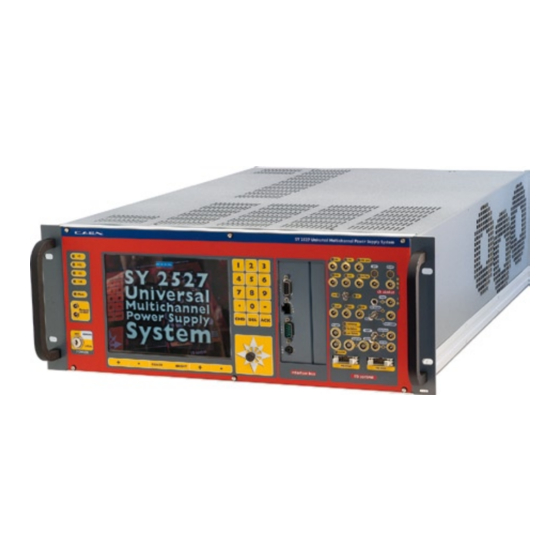
Page 84: Sy2527 System F Ront P Anel
Document type: Title: Revision date: Revision: User's Manual (MUT) Mod. SY2527, Universal Multichannel Power Supply System 27/11/2000 SY2527 System Front Panel NPO: Filename: Number of pages: Page: 00103/97:2527y.MUTx/00 SY2527USERMANUAL_REV0.DOC...
Need help?
Do you have a question about the SY 2527 and is the answer not in the manual?
Questions and answers