
Related Manuals for Caen SY 1527


Summary of Contents for Caen SY 1527
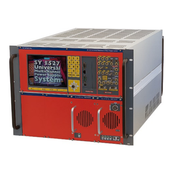
- Page 1 Hardware Installation Guide Revision n.3 3 December 2002 MOD. SY 1527 UNIVERSAL MULTICHANNEL POWER SUPPLY SYSTEM HARDWARE INSTALLATION GUIDE, REV.3 NPO: 00103/97:1527x.MUTx/03...
- Page 2 User. It is strongly recommended to read thoroughly the CAEN User's Manual before any kind of operation. CAEN reserves the right to change partially or entirely the contents of this Manual at any time and without giving any notice.
-
Page 3: Table Of Contents
Document type: Title: Revision date: Revision: Installation Guide (MUT) Mod. SY1527, universal multichannel power supply system 03/12/02 TABLE OF CONTENTS ABOUT THIS GUIDE ..........................6 ............................7 RGANISATION ............................8 ONVENTIONS 1.2.1 Safety rules ............................8 1.2.2 Electrical signal specifications......................8 GENERAL DESCRIPTION OF THE SYSTEM ..................9 .............................9 VERVIEW .......................11... - Page 4 Document type: Title: Revision date: Revision: Installation Guide (MUT) Mod. SY1527, universal multichannel power supply system 03/12/02 4.3.3.2 Interface bus section ..........................39 4.3.4 DISPLAYS........................... 40 4.3.5 SWITCHES ..........................41 4.3.6 BUTTONS ........................... 42 ....... 43 XTERNAL CONNECTORS DISPLAYS AND SWITCHES OF THE RIMARY OWER UPPLY...
-
Page 5: List Of Figures
Document type: Title: Revision date: Revision: Installation Guide (MUT) Mod. SY1527, universal multichannel power supply system 03/12/02 7.4.3 Remote operation via Web Browser ....................59 7.4.4 Remote operation via host computer ...................59 ............................59 ROUNDING SYSTEM POWER-ON ..........................60 ...........................60 RELIMINARY CHECK ..........................60 OCAL OWER ..........................61... -
Page 6: About This Guide
Document type: Title: Revision date: Revision: Installation Guide (MUT) Mod. SY1527, universal multichannel power supply system 03/12/02 1. About this guide The purpose of this guide is to illustrate: • the mechanical and electrical features of the SY1527 Universal Multichannel Power Supply System, •... -
Page 7: Organisation
Document type: Title: Revision date: Revision: Installation Guide (MUT) Mod. SY1527, universal multichannel power supply system 03/12/02 Organisation This guide is organised as follows: Chapter 1 – About this guide: it briefly describes this guide’s objectives and organisation; Chapter 2 – General description of the system: it contains an overview of the system and its main features, a very brief functional description and some reference tables with a summary of the system technical specifications;... -
Page 8: Conventions
Document type: Title: Revision date: Revision: Installation Guide (MUT) Mod. SY1527, universal multichannel power supply system 03/12/02 Conventions The conventions adopted all through this guide are briefly listed in the following. 1.2.1 Safety rules The user is requested to pay particular attention to the parts of the document containing the following terms: WARNING: Warning statements identify conditions or practices that could result in injury or... -
Page 9: General Description Of The System
The SY1527 system is the fully equipped, large scale experiment version of a new line of power supply systems which represent CAEN's latest proposal in the matter of High Voltage and Low Voltage Power Supplying. This system outlines a completely new... - Page 10 Mod. SY1527, universal multichannel power supply system 03/12/02 The User interface features the usual friendliness of the previous CAEN systems which now also includes a 7.7" colour LCD. A wide choice of communication interfaces provides full compatibility with the previous systems and the possibility of controlling heterogeneous external devices.
-
Page 11: Short Functional Description
Document type: Title: Revision date: Revision: Installation Guide (MUT) Mod. SY1527, universal multichannel power supply system 03/12/02 via network facilities. Actually, Telnet and WWW access facilities allow system’s remote debugging and technical support, including future firmware upgrading. Short Functional description A block diagram of the SY1527 system is shown in Fig. - Page 12 Document type: Title: Revision date: Revision: Installation Guide (MUT) Mod. SY1527, universal multichannel power supply system 03/12/02 If the Board has fixed current hardware protections, the output current is permitted to exceed the ISET value; the channel acts like a current generator only if the maximum current value is reached.
-
Page 13: Fig. 2.2 - Block Diagram Of The Functional Parts Of The Sy1527 System
Document type: Title: Revision date: Revision: Installation Guide (MUT) Mod. SY1527, universal multichannel power supply system 03/12/02 support. A special software interface has been developed for monitoring and setting of the system parameters from TCP/IP environment. Further remote control interfaces are available on request and can be inserted into the expansion slots on the front panel. -
Page 14: Technical Specification Table
Document type: Title: Revision date: Revision: Installation Guide (MUT) Mod. SY1527, universal multichannel power supply system 03/12/02 Technical specification table Table 2.1 - Technical specifications of the SY1527 mainframe: general - 19"-wide, 8U-high Euro-mechanics rack; Packaging - Depth: 720 mm. -Mainframe (*): 24 kg Weight -Mod. -
Page 15: Table 2.2 - Technical Specifications Of The Sy1527 Mainframe: Front / Rear Panel Components
Document type: Title: Revision date: Revision: Installation Guide (MUT) Mod. SY1527, universal multichannel power supply system 03/12/02 Table 2.2 - Technical specifications of the SY1527 mainframe: front / rear panel components (refer to the figure in Appendix A) − GEN, red LED, lights up when GENERAL STATUS signal, corresponding to a logic combination (defined by the user) of OVC, UNV, OVV, TRIP, is TRUE;... -
Page 16: Table 2.3 - Technical Specifications Of The Sy1527 Mainframe: Input And Output Signals
Document type: Title: Revision date: Revision: Installation Guide (MUT) Mod. SY1527, universal multichannel power supply system 03/12/02 Table 2.3 - Technical specifications of the SY1527 mainframe: input and output signals (refer to the figure in Appendix A) Std. NIM/TTL; 00-type LEMO connector. VSEL: Function: channel voltage selection. - Page 17 Document type: Title: Revision date: Revision: Installation Guide (MUT) Mod. SY1527, universal multichannel power supply system 03/12/02 All the above signals, except for the REMOTE IN/OUT, are referred to a common ground (COMMON GROUND) and are galvanically insulated up to 150 V with respect to the ground of the crate (CRATE GROUND).
-
Page 18: Description Of The Mechanical Parts
Document type: Title: Revision date: Revision: Installation Guide (MUT) Mod. SY1527, universal multichannel power supply system 03/12/02 3. Description of the mechanical parts This section contains a description, from a mechanical point of view, of the parts which constitute the SY1527 mainframe’s universal multichannel power supply system. The SY1527 mainframe and its mechanical parts The SY1527 system is hosted in an 8U-high, 19”-wide (84TE) EURO-mechanics rack. -
Page 19: Fig. 3.1 - Details Of The Mechanical Parts Contained In The Sy1527 Mainframe
Document type: Title: Revision date: Revision: Installation Guide (MUT) Mod. SY1527, universal multichannel power supply system 03/12/02 Interface Bus Board Section Backplane with 16 slots with 6 slots Interface Board for the I/O control Ethernet board Fan Unit with 6 horizontally- oriented fans CPU board Front Panel... -
Page 20: Board Section
Document type: Title: Revision date: Revision: Installation Guide (MUT) Mod. SY1527, universal multichannel power supply system 03/12/02 Board Section This section is located in the mainframe’s rear upper 6U-high part and hosts the 16 slots for the insertion of boards (refer to Fig. 2.1, p.9). This section is empty when it is delivered to the customer. - Page 21 Document type: Title: Revision date: Revision: Installation Guide (MUT) Mod. SY1527, universal multichannel power supply system 03/12/02 the system’s cooling. The six fans are disposed on two rows and are DC supplied through the relevant connectors placed on the Board Backplane. In order to make more uniform the system’s ventilation , the fans have been placed about 3 cm far from the boards so that ventilation from all sides is adequate.
-
Page 22: Power Supply Section
Document type: Title: Revision date: Revision: Installation Guide (MUT) Mod. SY1527, universal multichannel power supply system 03/12/02 Rear panel - High Boards Backplane Air Flow Power Supply Section Fans Rear panel - Low Fig. 3.2 –Air flow from the fan tray unit into the board section CAUTION THE DISTANCE FROM THE TOP OF A CRATE AND ANY OTHER OBJECT MUST BE AT LEAST 15 CM! -
Page 23: Power Supply Backplane
Document type: Title: Revision date: Revision: Installation Guide (MUT) Mod. SY1527, universal multichannel power supply system 03/12/02 WARNING: Both the primary power supply and the power supply units can be inserted or extracted from the appropriate housing only if the system main switch located on the rear panel is OFF (i.e. -
Page 24: Fig. 3.3 - Front Panel Of The Primary Power Supply (Mod. A1531)
Document type: Title: Revision date: Revision: Installation Guide (MUT) Mod. SY1527, universal multichannel power supply system 03/12/02 OK, yellow LED; lights up when the system is ON; +5, red LED; lights up when the +5 V power supply is present; if off, it indicates that there is a fault;... -
Page 25: Power Supply Units (Mod. A1532)
Document type: Title: Revision date: Revision: Installation Guide (MUT) Mod. SY1527, universal multichannel power supply system 03/12/02 WARNING: The primary power supply can be inserted or extracted from the appropriate housing only if the system is turned off and unplugged from the mains. -
Page 26: Fig. 3.4 - Front Panel Of The Power Supply Unit (Mod. A1532)
Document type: Title: Revision date: Revision: Installation Guide (MUT) Mod. SY1527, universal multichannel power supply system 03/12/02 position with respect to that of the bias pins of the Power Supply Units. When the system is delivered to the customer, the housings which are not used are covered with a panel. The front panel of the A1532 Power Supply Unit is shown in Fig. -
Page 27: Cpu Section
Document type: Title: Revision date: Revision: Installation Guide (MUT) Mod. SY1527, universal multichannel power supply system 03/12/02 CAUTION DO NOT COVER THE COOLING GRID! Table 3.2 – Mechanical and Electrical features of the A1532 Power Supply Unit 20TE-wide, 4U-high mechanics; Mechanical features Depth: 250 mm;... -
Page 28: Number Of Pages
Document type: Title: Revision date: Revision: Installation Guide (MUT) Mod. SY1527, universal multichannel power supply system 03/12/02 CAUTION THE EXTRACTION OF THE CPU SECTION BOX CAN BE PERFORMED BY QUALIFIED PERSONNEL ONLY! NPO: Filename: Number of pages: Page: 00103/97:1527x.MUTx/03 HWGUIDE_REV3.DOC... -
Page 29: Interface Bus Backplane
Document type: Title: Revision date: Revision: Installation Guide (MUT) Mod. SY1527, universal multichannel power supply system 03/12/02 3.5.1 Interface bus backplane The Interface bus backplane is an AT standard passive ISA bus with 6 16-bit slots. Two of these are occupied by the Interface Board and by the CPU Board (Fig. 3.1, p.19), while two of the four slots left are available for additional interface boards (refer to Section 3.5.4, p.29 for further details on the additional interface boards available for the SY1527 system). -
Page 30: Front Panel
Document type: Title: Revision date: Revision: Installation Guide (MUT) Mod. SY1527, universal multichannel power supply system 03/12/02 Front Panel The frontal part of the SY1527 mainframe is shown in Fig. 3.5, p.30. It can be essentially divided into two main sections: the higher 4U-high section which consists of the actual Front Panel;... -
Page 31: Lcd Screen, Keypad And Compact Switch
Document type: Title: Revision date: Revision: Installation Guide (MUT) Mod. SY1527, universal multichannel power supply system 03/12/02 3.6.1 LCD screen, keypad and compact switch The crate is provided with a VGA-standard 7.7” colour LCD screen (640x480 resolution). Four buttons (+/- CONTRAST and +/- BRIGHT), placed just below the screen, allow to adjust the brightness and contrast of the monitor. -
Page 32: I/O Control Section
Document type: Title: Revision date: Revision: Installation Guide (MUT) Mod. SY1527, universal multichannel power supply system 03/12/02 3.6.3 I/O Control Section The I/O Control section hosts the I/O connectors and several displays and switches for the system’s control. Output connectors The upper part of this area contains the OUTPUT connectors and relevant displays for the check of the channel status. - Page 33 Document type: Title: Revision date: Revision: Installation Guide (MUT) Mod. SY1527, universal multichannel power supply system 03/12/02 ISEL (CURRENT SELECTION) input connector and relevant green LED – it allows to select one of the two current limit values, I0SET and I1SET, programmed for the relevant channel.
- Page 34 Document type: Title: Revision date: Revision: Installation Guide (MUT) Mod. SY1527, universal multichannel power supply system 03/12/02 CAENET input/output connectors and relevant red LED – input/output connectors for CAENET communications. INTERLOCK input/output connector and relevant red LED – The INTERLOCK connector acts as an open/closed contact.
-
Page 35: Rear Panel
3KV 3mA 3KV 3mA Costruzioni Apparecchiature Elettroniche Nucleari SpA via Vetraia, 11 - I-55049 Viareggio (LU) ITALIA tel. +39 0584 388398 - fax +39 0584 388959 e-mail: info@caen.it - URL: http:\\www.caen.it SLOT 0 SLOT 15 VOLTAGE RANGE 100 - 230 V... -
Page 36: Technical Specifications
Document type: Title: Revision date: Revision: Installation Guide (MUT) Mod. SY1527, universal multichannel power supply system 03/12/02 4. Technical specifications Packaging The SY1527 mainframe is hosted in a 19"-wide, 8U-high Euro-mechanics rack. The depth of the mainframe is about 720 mm. The weight of the mainframe together with one Mod. -
Page 37: Outputs
Document type: Title: Revision date: Revision: Installation Guide (MUT) Mod. SY1527, universal multichannel power supply system 03/12/02 Function: RESET from the front panel. If the RESET signal is > T RCPU 100÷200 ms, only the CPU is reset; if it is > T + 900 ms, also RCPU the boards are reset and the channels which are ON are turned off. -
Page 38: I/O Connectors
Document type: Title: Revision date: Revision: Installation Guide (MUT) Mod. SY1527, universal multichannel power supply system 03/12/02 GEN: Mechanical specifications: 00-type LEMO connector. Electrical specifications: std. NIM level or TTL level. Function: GENERAL STATUS indication; corresponds to the logic combination, defined by the user, of OVC, UNV, OVV, TRIP. 4.3.3 I/O CONNECTORS 4.3.3.1 I/O control section... -
Page 39: 4.3.3.2 Interface Bus Section
Document type: Title: Revision date: Revision: Installation Guide (MUT) Mod. SY1527, universal multichannel power supply system 03/12/02 4.3.3.2 Interface bus section The following interface connectors are placed in the Interface bus area of the front panel: RS232 INTERFACE: Mechanical specifications: 9-pin D-type male RS232 serial port. Electrical specifications: Refer to Fig. -
Page 40: Displays
Document type: Title: Revision date: Revision: Installation Guide (MUT) Mod. SY1527, universal multichannel power supply system 03/12/02 Table 4.1 – RS232 Port Default Settings Baud rate 57600 Parity None Character length 8 bits Number of stop bits 1 bit Control flow Xon/Xoff The following interface boards are Optional and the relevant connectors, consequently, may not be present depending on the configuration the user has ordered:... -
Page 41: Switches
Document type: Title: Revision date: Revision: Installation Guide (MUT) Mod. SY1527, universal multichannel power supply system 03/12/02 KILL: Mechanical specifications: green LED. Function: it lights up when the KILL signal is TRUE. NIM: Mechanical specifications: green LED. Function: it lights up when the NIM standard is selected. TTL: Mechanical specifications: green LED. -
Page 42: Buttons
Document type: Title: Revision date: Revision: Installation Guide (MUT) Mod. SY1527, universal multichannel power supply system 03/12/02 LOC ENABLE/DISABLE/REM ENABLE: Mechanical specifications: three-position lever switch. Function: LOCAL ENABLE / DISABLE / REMOTE ENABLE, it allows disabling the voltage generation on the channel boards or enabling it either locally or remotely via a proper input signal: Upper position: the local enable mode is selected;... -
Page 43: External Connectors, Displays And Switches Of The Primary Power Supply
Document type: Title: Revision date: Revision: Installation Guide (MUT) Mod. SY1527, universal multichannel power supply system 03/12/02 LED will be red), only the CPU will be reset. If the button is pressed for more than T + 900 ms (the LED will become orange), RCPU also the boards will be reset and the channels which are ON are reset. -
Page 44: Switches
Document type: Title: Revision date: Revision: Installation Guide (MUT) Mod. SY1527, universal multichannel power supply system 03/12/02 Function: it lights up when the +5 V power supply is present; if it is off it indicates that there is a fault. +12: Mechanical specifications: green LED. -
Page 45: Switches
Document type: Title: Revision date: Revision: Installation Guide (MUT) Mod. SY1527, universal multichannel power supply system 03/12/02 4.6.2 SWITCHES MAIN SWITCH: Mechanical specifications: magneto-thermal switch. Function: it is used to power the Power Supply Section of the system. It has two positions: 0, the Power Supply Section is not powered;... -
Page 46: Unpacking The System
Document type: Title: Revision date: Revision: Installation Guide (MUT) Mod. SY1527, universal multichannel power supply system 03/12/02 5. Unpacking the system Check list Before installing the SY1527 check the list in Table 5.1 containing all the parts you need to install the system. Table 5.1 –... -
Page 47: Safety Information And Installation Requirements
Document type: Title: Revision date: Revision: Installation Guide (MUT) Mod. SY1527, universal multichannel power supply system 03/12/02 6. Safety information and installation requirements This section contains the fundamental safety rules for the installation and operation of the SY1527 system. Read this section thoroughly before starting any procedure of installation or operation of the product. -
Page 48: Product Damage Precautions
Document type: Title: Revision date: Revision: Installation Guide (MUT) Mod. SY1527, universal multichannel power supply system 03/12/02 6.1.2 Product Damage Precautions Use Proper Power Source. Do not operate this product from a power source that applies more than the voltage specified. -
Page 49: Terms And Symbols On The Product
Document type: Title: Revision date: Revision: Installation Guide (MUT) Mod. SY1527, universal multichannel power supply system 03/12/02 Terms and Symbols on the Product These terms may appear on the product: • DANGER indicates an injury hazard immediately accessible as you read the marking. -
Page 50: Hardware Installation And Set-Up
Document type: Title: Revision date: Revision: Installation Guide (MUT) Mod. SY1527, universal multichannel power supply system 03/12/02 7. Hardware installation and set-up Installation Before installing the system, make sure you have read thoroughly the safety rules and installation requirements listed in Section 6, p.47. For the installation of the SY1527 system in its basic standalone configuration, the following parts are needed (see also the Check List at page 46): •... - Page 51 Document type: Title: Revision date: Revision: Installation Guide (MUT) Mod. SY1527, universal multichannel power supply system 03/12/02 To install the Power Supply Units: Turn the system off by the main switch located on the rear panel (refer to Fig. 3.6, p.35 for its location), disconnect the system from the mains and wait for at least 1 minute;...
-
Page 52: Installing The Boards
Document type: Title: Revision date: Revision: Installation Guide (MUT) Mod. SY1527, universal multichannel power supply system 03/12/02 WARNING DO NOT INSERT OR EXTRACT ANY POWER SUPPLY BEFORE THE SYSTEM IS TURNED OFF AND UNPLUGGED FROM THE MAINS! 7.1.2 Installing the boards Both boards and distributors have to be inserted in the Board and Distributor Section located in the rear upper part of the mainframe (refer to Fig. -
Page 53: Connecting The System To The Mains
Document type: Title: Revision date: Revision: Installation Guide (MUT) Mod. SY1527, universal multichannel power supply system 03/12/02 7.1.3 Connecting the system to the mains A Power Supply cable is provided with the system to connect it to the mains. To connect the system to the mains, follow this procedure: 1. -
Page 54: Operating Modes And Relevant Hardware Set-Ups
Document type: Title: Revision date: Revision: Installation Guide (MUT) Mod. SY1527, universal multichannel power supply system 03/12/02 Operating modes and relevant hardware set-ups The flexibility of the SY1527 system offers a wide range of different hardware set-ups to operate the system. These can be schematically referred to four main categories which emphasise the way of operating the SY1527 system and the type of external devices used to control it. -
Page 55: Remote Operation Via Terminal
Document type: Title: Revision date: Revision: Installation Guide (MUT) Mod. SY1527, universal multichannel power supply system 03/12/02 7.3.2 Remote operation via Terminal Remote Operation via Terminal is intended as the interactive control and monitoring of one or more SY1527 systems by using a remote terminal. The remote operation via terminal can be performed in different ways, according to the interface used to communicate with the system. -
Page 56: Remote Operation Via Web Browser
Document type: Title: Revision date: Revision: Installation Guide (MUT) Mod. SY1527, universal multichannel power supply system 03/12/02 7.3.3 Remote Operation via Web Browser This feature will be available with the Software Version 2.00 or later. 7.3.4 Remote operation via Host Computer This feature will be available with the Software Version 2.00 or later. -
Page 57: Remote Operation Via Terminal
Document type: Title: Revision date: Revision: Installation Guide (MUT) Mod. SY1527, universal multichannel power supply system 03/12/02 VGA port Ethernet interface (10baseT connector) RS232 interface PS/2 connector (keyboard) Interface Bus Fig. 7.3 – Location of RS232 interface, VGA port, PS/2 connector and Ethernet interface 7.4.2 Remote operation via terminal The definition of remote operation via terminal and the relevant hardware set-ups are... -
Page 58: Fig. 7.4 - Electro-Mechanical Specifications Of The Rs232 Cable (9-Pin To 9-Pin)
Document type: Title: Revision date: Revision: Installation Guide (MUT) Mod. SY1527, universal multichannel power supply system 03/12/02 To the SY1527 system To the terminal Carrier Detect Carrier Detect Data Set Ready Data Set Ready Receive Data Receive Data Request to Send Request to Send Transmit Data Transmit Data... -
Page 59: Using H.s. Caenet (Multicrate Operation)
Document type: Title: Revision date: Revision: Installation Guide (MUT) Mod. SY1527, universal multichannel power supply system 03/12/02 7.4.2.2 Using H.S. CAENET (Multicrate Operation) The operation of the SY1527 system from a terminal not directly connected to the crate can be performed by using H.S. CAENET interface (for details on the H.S. CAENET Network please refer to the User's Manual). -
Page 60: System Power-On
Document type: Title: Revision date: Revision: Installation Guide (MUT) Mod. SY1527, universal multichannel power supply system 03/12/02 8. System Power-On The system’s Power-ON can be performed either locally or remotely, as described in the following subsections. For a full description of the operating modes and software interfaces please refer to the User’s Manual. -
Page 61: Remote Power-On
Document type: Title: Revision date: Revision: Installation Guide (MUT) Mod. SY1527, universal multichannel power supply system 03/12/02 -12 (green LED on PPS): it indicates the presence of -12 V power supply; if off, it indicates that there is a fault. +48 (green LED on PSU): it indicates the presence of +48 V power supply;... - Page 62 Document type: Title: Revision date: Revision: Installation Guide (MUT) Mod. SY1527, universal multichannel power supply system 03/12/02 APPENDIX A NPO: Filename: Number of pages: Page: 00103/97:1527x.MUTx/03 HWGUIDE_REV3.DOC...
-
Page 63: Sy1527 System
Document type: Title: Revision date: Revision: Installation Guide (MUT) Mod. SY1527, universal multichannel power supply system 03/12/02 SY1527 System Front Panel NPO: Filename: Number of pages: Page: 00103/97:1527x.MUTx/03 HWGUIDE_REV3.DOC...
Need help?
Do you have a question about the SY 1527 and is the answer not in the manual?
Questions and answers