Table of Contents
Advertisement
Quick Links
Advertisement
Table of Contents
Troubleshooting

Related Manuals for YOKOGAWA TDLS220


Summary of Contents for YOKOGAWA TDLS220
- Page 1 User’s TDLS220 Manual Tunable Diode Laser Spectroscopy Analyzer IM 11Y01B02-01E-A IM 11Y01B02-01E-A Yokogawa Corporation of America 2 Dart Road, Newnan, Georgia U.S.A. 30265 3rd Edition Yokogawa Corporation of America Tel: 1-800-888-6400 Fax: 1-770-254-0928...
- Page 2 Media No. IM 11Y01B02-01E-A 3rd Edition :June. 2012 (USA) IM 11Y01B02-01E-A 3rd Edition June 19, 2012-00 All Rights Reserved Copyright © 2012, Yokogawa Corporation of America...
- Page 3 Warning and Disclaimer The product is provided on an “as is” basis. YOKOGAWA shall have neither liability nor responsibility to any person or entity with respect to any direct or indirect loss or damage arising from using the product or any defect of the product that YOKOGAWA cannot predict in advance.
- Page 4 SAFETY should be considered first and foremost importance when working on the equipment described in this manual. All persons using this manual in conjunction with the equipment must evaluate all aspects of the task for potential risks, hazards and dangerous situations that may exist or potentially exist.
- Page 5 Warranty and service Yokogawa products and parts are guaranteed free from defects in workmanship and material under normal use and service for a period of (typically) 12 months from the date of shipment from the manufacturer. Individual sales organizations can deviate from the typical warranty period, and the conditions of sale relating to the original purchase order should be consulted.
- Page 6 TOC-1 Table of Contents Preface ............................i Safety Precautions ........................ii Quick Start ........................1-1 Introduction and General Description ................. 2-1 2.1 Functional Decription ....................2-1 2.1.1 Measurement .......................2-2 General Specifications ....................3-1 Analyzer Components ....................4-1 4.1 Main Electronic Housing ...................4-1 4.2 Process Interface ......................4-4 4.3 Communications ......................4-4 4.4 Software ........................4-7...
- Page 7 TOC-2 Troubleshooting ......................8-1 8.1 Common Troubleshooting Step .................8-2 8.1.1 On Process Gas or Zero Gas or Span Gas ............8-2 8.1.2 Trouble Shooting procedure for lost and /or Low Transmission ......8-3 8.2 Analyzer Warnings .....................8-3 8.3 Analyzer Faults ......................8-4 Data Files and Format ....................9-1 9.1 Configuring Data Capture ..................9-5 9.2 downloading the Data ....................9-8 Revision Record ..........................
-
Page 8: Quick Start
Ensure the appropriate utilities are available and ready for connection. These may include electri- cal power, nitrogen purge gas, instrument air, validation gas, etc. Make sure the sample handling and conditioning system meets the sample inlet and outlet requirements for TDLS220. Refer to Section XX “Installation” for details. - Page 9 Advanced Menu needs to be accessed. Advanced Menu access is Password protected (default 1234, can be changed by user if neces- sary) and should only be used by skilled and trained persons - Contact Yokogawa Laser Analysis Division or Local Agent if any doubts! Go to the Data section under Basic and configure the appropriate ‘Record Result Data’...
- Page 10 Failure to do so may result in damage and can void any warranty! If there is any doubt about any aspect of the Instrument installation or use, please contact Yokogawa Laser Analysis Division and/or your authorized Representative/Distributor.
-
Page 11: Introduction And General Description
(most often Oxygen or Moisture) in gas phase samples that have been extracted from the process. Typically, there is a continuous flow of analyzed gas through the TDLS220 optical gas cell. The gas should be pre-conditioned to meet the sample inlet requirements including (but not limited to) particulate removal, dew point control (heated), flow and pressure control, etc. -
Page 12: Measurement
<2 INTRODUCTION AND GENERAL DESCRIPTION> 2-2 2.1.1 Measurement • During measurement the laser is held at a fixed temperature. This is the coarse wavelength adjustment. Current ramp to laser • A current ramp is fed to the laser. This is the fine wave length adjustment. -
Page 13: Environmental Specifications
<3 GENERL SPECIFICATIONS> 3-1 3 General Specifications Environmental Specifications Measurement range: Dependent on application. Ranges from 0-1% up to 0-25% for analysis of Oxygen. Ambient Temperature: -10 to +50 °C Output signal: (3x) 4- 20mA DC with maximum load of Humidity: 0- 90 % RH non-condensing or 900 Ohm... - Page 14 : 0.01% detection limit, Min Range Basic Menu 0-1%, Max range 25% Configure, 3 functions Performance Specifications are application dependant. View Spectra, 2 functions *Consult Yokogawa for ranges; All Data, 3 sub-menus performance specifications are for 25ºC at Trends 1 bar. Advanced Menu:...
- Page 15 <3 GENERL SPECIFICATIONS> 3-3 Model and Suffix Codes Model TDLS220 Model TDLS220 Tunable Diode Laser Gas Analyzer Tunable Diode Laser Gas Analyzer Model Su x Option Description TDLS220 ------------------------------------------------ --------- Tunable Diode Laser General Purpose Type -G1--------------------------------------------- --------- NEC Class 1 Div 2 BCD...
-
Page 16: Analyzer Components
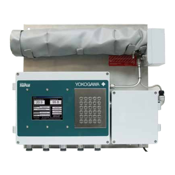
<4 ANALYzER COMPONENTS> 4-1 Analyzer Components Figure 2 - System Overview 4.1 Main Electronics Housing Enclosure Die cast copper free aluminum grade AL Si 12 alloy (A413.0) with a powder coat exterior finish. The copper free aluminum alloy is particularly resistant to salt atmospheres, sulfur gases and galvanic corrosion. An externally hinged door opening to the left incorporates a weather tight gasket seal and four captive fastening screws (stainless steel). - Page 17 <4 ANALYzER COMPONENTS> 4-2 approx 5” W x 4” H (130mm x 100mm). A clear laminated safety glass window is mounted to the inside of the door with stainless steel fasteners and a weather tight gasket. This allows for external viewing of the actual display without opening the door.
- Page 18 <4 ANALYzER COMPONENTS> 4-3 Calibration Valve Relays There are three calibration valve relay circuits on the board. These are capable of actuating Form C SPDT relays. The common pole is connected to 24VDC power and the normally open pole is routed to the field terminal block.
-
Page 19: Process Interface
TB6 – Ethernet 10/100 4.2 Process Interface The TDLS220 is provided with a flow cell through which the process sample gas flows. Different cell materials and window seal materials may be used pending application. ¼” Swagelok tube fit- tings are typical connection size for the purge and process gases. - Page 20 <4 ANALYzER COMPONENTS> 4-5 Remote Interface Options A number of options are available for remote access to the analyzer Remote Interface Unit (RIU) shown below allows remote analyzer control and data transfer from analyzer to RIU (data can be transferred from RIU via USB memory stick or Compact Flash card.
- Page 21 <4 ANALYzER COMPONENTS> 4-6 RIU Interconnect to TDLS220 Control Unit(s) When connecting just one analyzer to the RIU there are two twisted pair wires to consider , there are only four wires to be terminated to make the 10/100 Ethernet connection...
-
Page 22: Software
<4 ANALYzER COMPONENTS> 4-7 4.4 TruePeak TDLS220 Software The TDLS220 Analyzer Software has three significant design criteria based on the previously field proven TDLS200 software (TruePeak): • Extensive Capabilities & Features • Intuitive Menu Structure & Commands • Easy Operation The software loads itself automatically upon analyzer power-up and the initial display is the MAIN MENU. - Page 23 <4 ANALYzER COMPONENTS> 4-8 Basic Menu Typical Trend Screen Figure 7 - Software Overview IM 11Y01B02-01E-A 3rd Edition June 19, 2012-00...
-
Page 24: Installation And Wiring
Refer to the SAFETY section (Safe handling and relocation) for instructions on holding and moving the analyzer. The TDLS220 is suitable for wall mounting by means of the four corner located mounting holes as shown below: The holed are ½” sized for typically 3/8” or ¼” bolts and should be used with appropriate sized flat and locking washers. -
Page 25: Sample Inlet And Outlet Considerations
<5 INSTALLATION AND WIRING> 5-2 5.2 Sample Inlet and Outlet Considerations The following criteria should be considered when selecting the installation point in respect to the process conditions (1/4” OD Swagelok tube fittings): Process Gas Condition: - The sample should be clean, dry, non-condensing at the inlet to the sample cell. -
Page 26: Wiring Details
<5 INSTALLATION AND WIRING> 5-3 Wiring Details Connect protective ground to the designated terminal of the analyzer. Use minimum 14 AWG or equivalent. The analyzer mains must be connected to an end user provided disconnect device with 250V, 10 A ratings. Screw Terminal Block (SAk2.5) Details: (also see following diagram for internal wiring). - Page 27 <5 INSTALLATION AND WIRING> 5-4 Factory Ethernet + Transmit - Transmit + Receive - Receive Factory Detect Internal connections only – do not use Field Analog Cal/Val initiate signal loop (SV # 1) to Remote voltage #1 output free contacts/switch. Do not apply external power! Analog Cal/Val initiate signal loop (SV # 2) to Remote voltage #2 output...
-
Page 28: Purge Gas Requirements And Hazardous Area Systems
5.4 Purge Gas Requirements and Hazardous Area Systems The TDLS220 Analyzer requires a continuous nitrogen (optionally instrument air) gas purge to prevent ambient oxygen ingress to the optical path, when oxygen is the measured gas. The flow rate can be minimized as long as it prevents any ambient oxygen ingress to the measurement optical path. - Page 29 <5 INSTALLATION AND WIRING> 5-6 I/A Purge Inlet LASER & FLOW CELL DETECT POWER I/A Purge Vent HEAT ELECTRONICS TRACE CONTROLLER Figure 11 – Safe Area/General Purpose I/A Analyzer Purge Schematic I/A Purge Inlet Purge Inlet N2 Purge Inlet General Purpose LASER &...
- Page 30 <5 INSTALLATION AND WIRING> 5-7 Purge Inlet N2 Purge Inlet Hazardous Area LASER & Div 2 BCD ATEX CAT3 FLOW CELL DETECT POWER HEAT ELECTRONICS TRACE Purge Vent N2 Purge Vent CONTROLLER Figure 13 – Hazardous Area N Analyzer Purge Schematic I/A Purge Inlet Hazardous Area...
-
Page 31: Basic Operation
<6 BASIC OPERATION> 6-1 6 Basic Operation Only the numerical keys, arrow keys, ENTER, ESC and BACKSPACE keys are used to control the analyzer. Their functions are determined by the context-sensitive menus of the analyzer software. The misuse of keys is not possible (rejected by software). - Page 32 <6 BASIC OPERATION> 6-2 Online Menu Level 1 Menu Level 2 Menu Level 3 Menu Level 4 Menu Level 5 Menu ADVANCED Configure System I/O Analog Output Channel 1 Conc1/Conc2/Tran/Temp/Pres/ *Password None Protected 4 mA- 20 mA Channel 2* Channel 3* *(similar to Channel 1) Warning Mode Block Mode...
- Page 33 <6 BASIC OPERATION> 6-3 Online Menu Level 1 Menu Level 2 Menu Level 3 Menu Level 4 Menu Level 5 Menu ADVANCED Calibration Offline Calibration zero Calibraton Manual *Password Protected Automatic Local Initate Remote Initiate: control channel Time Initate: frequency Settings: valve, purge, tiime, AO mode Restore...
- Page 34 Span Calibrating… Validation Status Offline Validating… Online Validating… Data Transferring… Data Transfer Status Transfer Success Transfer Failure YOKOGAWA TDLS220 Analyzer Name SN 76-1xxx-05-xx Analyzer Serial No. AO1: CONC xx-xx%/ppm/ppb Configured 4-20mA output for AO2: TRANS xx-xx% AO1, AO2, & AO3 AO3: TEMP xx-xxF/C/K 10.0.0.35...
-
Page 35: Software Guide
<6 BASIC OPERATION> 6-5 6.2 Software Guide MAIN MENU Display of Concentration & Transmission Status Window – notification of initiating, working properly, warnings or faults Gas Temperature Gas Pressure Selection of Basic or Advanced Menu Active Alarm Display Button Analyzer Shut Down Button Tag number and serial number Analyzer date and time After selection of either Basic or Advanced Menu... - Page 36 RECORD RESULT DATA – The default setting during normal operation is “User Data”. The system should only be switched to “Factory Data” when advised by Yokogawa Laser Analysis Division. Note: recording Factory Data is only for specific diagnostic purposes and should not be selected under normal operation.
- Page 37 (internal analyzer optical path).. For details, see section 4.4. Use this feature if the TDLS220 is being purged with Instrument Air (I/A) IM 11Y01B02-01E-A 3rd Edition June 19, 2012-00...
- Page 38 <6 BASIC OPERATION> 6-8 UNITS – selection of units for path length (in, ft, cm, m), pressure (psiA, barA, kPa, torr, atm) and temperature (ºF, ºC, ºK). SYSTEM I/O – allows set up and assigning of analyzer Analog and Digital I/O. SYSTEM –...
- Page 39 <6 BASIC OPERATION> 6-9 SYSTEM I/O – ANALOG INPUT Pre-calibrated at factory and not normally required. Allows calibration of 4 to 20mA input channels; follow onscreen instruction. SYSTEM I/O - DIGITAL OUTPUT Setting of Digital Output assignments (DO 1-3) CHANNEL 1 WARNINGS – Setting of levels that will trigger analyzer warning and subsequent DO.
- Page 40 <6 BASIC OPERATION> 6-10 CONCENTRATION OUT OF RANGE – upper and lower levels at which process gas concentration read- ing will trigger a warning. BOARD TEMPERATURE OUT OF RANGE – warning that analyzer internal temperature is excessive. VALIDATION FAILURE – a validation failure will trigger a warning;...
- Page 41 <6 BASIC OPERATION> 6-11 VALVE CONTROL Typically used when the analyzer is configured with a flow cell in an offline application. VALVE CONTROL The valve control includes manual and automatic control. MANUAL – allows for manual ON/OFF control of the valve driver output signals.
- Page 42 1 through 3. ONLINE VALIDATIONS – DO NOT USE THIS FEATURE on TDLS220 OFFLINE CALIBRATIONS – use for all TDLS220 zERO CALIBRATION – manual or automatic calibration of Zero. zERO OFFSET – allows manual adjustment of Zero by applying a concentration offset.
- Page 43 RECORD RESULT DATA – The default setting during normal operation is “User Data”. The system should only be switched to “Factory Data” when advised by Yokogawa Laser Analysis Division. Note: recording Factory Data is only for specific diagnostic purposes and should not be selected under normal operation.
-
Page 44: Non-Process Parameters
6.3 Non-Process Parameters (required when Instrument Air Purging) Non-Process Parameters is the Yokogawa Laser Analysis Division term used to define regions of the op- tical path that may be purged with a gas containing the actual target (measured) gas. The most common application of this is to use Instrument Air (~20.9% O2) as the purge gas for analyzers measuring Oxy-... - Page 45 This is the pressure of the non-process gas. Typically, this will be close to atmospheric pressure of 1.01BarA or 14.7PsiA. Check the actual operating conditions and enter the appropriate value. Contact Yokogawa if unsure. NON-PROCESS TEMPERATURE This is the temperature of the non-process gas with two...
-
Page 46: Stream Switching And Valve Control Outputs
3 process streams are connected to 3 gas valves then to the inlet of the TDLS220 flow cell. The gas valves are controlled by three 24V relay output signals from the launch unit of the analyzer. During normal operation, only one valve can be open at a time. - Page 47 <6 BASIC OPERATION> 6-17 There are 3 ways to control the valves: manual control in software, automatic valve change in time sequence and remote override though digital contact. The following software description defines how to configure the sequencing and timing of the valves when used in a stream switching configuration: ADVANCED CONFIGURE MENU The software setup for the stream switching is configured in...
- Page 48 <6 BASIC OPERATION> 6-18 Note: all three valves can be off at same time. TIME SEQUENCE The valves can be controlled automatically based on the time sequence. As an example of the left setting, Valve 1 stays on for 60 minutes before switching to Valve 2. By setting the Time Sequence of all 3 valves, the stream switching can be implemented continuously and periodically.
-
Page 49: Controlling The Analyzer Remotely Or Locally Via External Pc/Laptop
Control box open. Windows 98SE or later (is required on computer to be connected to the analyzer), and crossover Ethernet cable. Contact your local Yokogawa agent for a free copy of the necessary “Ultra-VNC.exe” file that will enable the VNC connection with the analyzer. This Ulta-VNC.exe file should be loaded on to the connecting PCs desktop ready for use when connecting with the analyzer. -
Page 50: Using Ultra-Vnc Software
“Connect” button. If a successful connection is established then use the default password for entering the VNC connection screen is 1234 – see screen below that shows an example IP address of 10.0.200.2 (TDLS220 analyzer Serial number 220-XX-1402-XX etc.): DO NOT attempt to change of the “Quick Options” or any other settings on this menu! ... -
Page 51: Remote Interface Unit (Riu)
<6 BASIC OPERATION> 6-21 6.5.3 OPTIONAL Remote Interface Unit (RIU) The OPTIONAL RIU runs the Virtual Analyzer Controller (VAC) software described below. 6.5.4 Virtual Analyzer Controller (VAC) Operating Software Map IM 11Y01B02-01E-A 3rd Edition June 19, 2012-00... -
Page 52: Virtual Analyzer Controller (Vac) Operating Software Guide
Allow for file transfer from an analyzer to a local USB port (for memory device) Create connections by name and/or IP address OFFLINE CALIBRATIONS – use for all TDLS220 ZERO CALIBRATION – manual or automatic calibration of Zero. ZERO OFFSET – allows manual adjustment of Zero by applying a concentration offset. - Page 53 <6 BASIC OPERATION> 6-23 After selecting “Configuration – F4” you will be allowed to C onfiguration select the analyzer (with description and IP address) you wish to configure. You will be given the following menu choices: Create Connection - F2: This will allow programming of Tag Name and IP Address for future connections Delete Connection - F3: This is to delete an existing connection...
-
Page 54: Routine Maintenance
<7 ROUTINE MAINTENANCE> 7-1 7 Routine Maintenance The TDLS220 TDL analyzer requires little routine maintenance if it has been correctly installed, set-up and calibrated. This section will outline the routine maintenance procedures. Maintenance procedures require opening enclosures of certain modules. Make sure that there is no ingress of water or other liquids into the analyzer modules during these procedures. - Page 55 <7 ROUTINE MAINTENANCE> 7-2 Figure 17 - Mirror and Window Locations Mirror Removal for Cleaning or Replacement: Follow the precautions outlined in the “Thermal hazard” and “Chemical hazard” sections of the SAFETY chapter. If the flow cell becomes contaminated then it may be cleaned using the following procedure: •...
- Page 56 <7 ROUTINE MAINTENANCE> 7-3 • Carefully remove all four fasteners and lock washers and the mirror mounting plate The mirror is not fastened or adhered to the mounting plate so during removal, keep the mounting plate tilted up-wards to prevent the mirror from falling out of the mounting plate ...
- Page 57 <7 ROUTINE MAINTENANCE> 7-4 • Visually inspect the o-ring and replace if necessary. • Cleaning of the mirror should be performed as follows while taking great care not to scratch the surface of the mirror. • First, any loose impediments and dirt should be blown off the surface using a clean compressed gas source.
- Page 58 Use a second clean, dry tissue and wipe in one direction only to dry the surface. Inspect for cleanliness and if necessary, repeat the process. NOTE: If suitable cleaning media are not available then contact Yokogawa service group and a cleaning kit can be purchased.
- Page 59 <7 ROUTINE MAINTENANCE> 7-6 Window Removal for Cleaning or Replacement: Follow the precautions outlined in the “Thermal hazard” and “Chemical hazard” sections of the SAFETY chapter. If the flow cell becomes contaminated then it may be cleaned using the following procedure: •...
- Page 60 <7 ROUTINE MAINTENANCE> 7-7 • Using 7/64” Allen key carefully insert through the access holes and remove the four window retaining screws and lock washers – use long needle nose pliers to carefully hold each screw as it comes lose. •...
- Page 61 <7 ROUTINE MAINTENANCE> 7-8 THE WINDOW COULD BE HOT FROM THE HEATED CELL • This process wetted window is constructed of sapphire and is therefore more durable than the mirror surface. Use a clean, dry instrument air or nitrogen pressure (or canned air) supply to first blow off any particulate matter.
- Page 62 CAUTION! – Do not cross-thread the Phillips head screws into the cover • Check the Zero and Span with appropriate gases. • If there is no change in transmission and/or the results are still noisy/unexpected then contact Yokogawa for further assistance. IM 11Y01B02-01E-A 3rd Edition June 19, 2012-00...
-
Page 63: Analog Signal Field Loop Check
Once finished with the loop check, go back to the main menu using the ESC key 7.3 Data Reporting, Storage and Retrieva The TDLS220 analyzer has been designed with extensive data reporting capabilities. All data is available in the analyzer as a text file for import into a spreadsheet for analysis Data stored in the analyzer: •... -
Page 64: Validation And Calibration
<7 ROUTINE MAINTENANCE> 7-11 7.4 Validation and Calibration There are several methods that can be used to validate and/or calibrate the TDLS220 TDL analyzer. Generally, we recommend routine validation of the analyzer either on-line (if appropriately set-up) or off- line. - Page 65 <7 ROUTINE MAINTENANCE> 7-12 Following the on screen directions, enter in the: Pressure= Cell Pressure Temperature= Cell Temperature Cell length= 40” Concentration of the target gas inside the gas flow cell. Press Enter to proceed. Wait for the reading to stabilize. Press 9 to proceed.
- Page 66 Please see below for detailed explanations of Validation Settings. There are several critical parameters that must be preconfigured in the TDLS220 software when using the automatic validation sequence. These parameters MUST be correctly set otherwise the analyzer will report false/incorrect validation results.
-
Page 67: Off-Line Manual/Automatic Calibration
Follow the detailed on-screen instructions We do not recommend calibrating the Zero. If the Zero reading appear incorrect, then ensure all data results and spectra have been stored and send the files to Yokogawa Laser Analysis Division for further evaluation. - Page 68 <7 ROUTINE MAINTENANCE> 7-15 IM 11Y01B02-01E-A 3rd Edition June 19, 2012-00...
-
Page 69: Troubleshooting
<8 TROUBLESHOOTING> 8-1 8 Troubleshooting The TDLS220 TDL Analyzer troubleshooting is fairly simple for a process analyzer. First, virtually all components used in the system have a long Mean Time Between Failures (MTBF) with rated life of components typically exceeding 10 years (when operating within their stated specifications). Second, most probable failures and problems are diagnosed by the system, generating internal warning and fault conditions. -
Page 70: Common Troubleshooting Step
Under any warning conditions it is recommended that the following steps are carried out prior to contacting YOKOGAWA. 8.1.1 On Process Gas or zero Gas or Span Gas Check Status LEDs. -
Page 71: Trouble Shooting Procedure For Lost And /Or Low Transmission
<8 TROUBLESHOOTING> 8-3 • Record Results. Download data files from the analyzer for e-mail to Yokogawa Laser Analysis Division. 8.1.2 Trouble Shooting Procedure for Lost and/or Low Transmission For a TDL analyzer to function correctly there must be a suitable amount of the laser light reaching the detector. -
Page 72: Analyzer Faults
Range. Indication that the system can not keep the peak centered in the scan range. Please review the absorption spectra to check the actual peak position, check that some target gas in the optical path – capture spectra and send to Yokogawa Laser Analysis Division or local agent for further assistance. -
Page 73: Data Files And Format
All the files are stored in simple ASCII text format for easy importing to MS Excel spreadsheets (or other data manipulation software as appropriate). The rate at which data is captured may be configured from within the TDLS220 software. There are several files that are stored in the system:... - Page 74 <9 DATA FILES AND FORMAT> 9-2 These files are the individually named spectra that are “Captured” by the user at any given date or time during operation. Each file can have up to 8 numerals in its name which are entered at the time the “Capture” is Capture -------- .cap...
-
Page 75: System Configuration
<9 DATA FILES AND FORMAT> 9-3 Calibration History - When the calibr.his file exceeds 100KB size the contents is saved to this .bak file and the .his file is emptied. This .bak file is in the form of ASCII data files that can be opened with Microsoft “Notepad”... - Page 76 <9 DATA FILES AND FORMAT> 9-4 System Configuration History - When the system.his file exceeds 100KB size the contents is saved to this .bak file and the .his file is emptied. This .bak file is in the form of ASCII data files that can be opened with Microsoft “Notepad”...
-
Page 77: Configuring Data Capture
The default setting during normal operation is “User Data”. The system should only be switched to “Factory Data” when advised by Yokogawa Laser Analysis Division. Note: recording Factory Data is only for specific diagnostic purposes and should not be selected under normal operation. - Page 78 <9 DATA FILES AND FORMAT> 9-6 To select the Spectrum capture, stay in Advanced Menu user mode and the Data sub section – select Spectrum Capture To store spectrum automatically, select Auto. If you do not wish to store any spectrum file during normal analyzer operation, then select Manual mode.
- Page 79 <9 DATA FILES AND FORMAT> 9-7 Determine whether or not the analyzer should capture spectrum files under a WARNING condition. Note: this may be useful to do so however, if the Warning alarm conditions are not set correctly then there could be excessive files created for less meaningful Warning alarm conditions.
- Page 80 <9 DATA FILES AND FORMAT> 9-8 9.2 Downloading (Transferring/Exporting) the Data: All the files can be easily transferred from the analyzer to the supplied USB memory device. NOTES: Please use the supplied “SanDisk” USB memory device with when getting data from the analyzer. Each analyzer is supplied with one pre-tested USB memory devices –...
- Page 81 <REVISION RECORD> i <REVISION RECORD> i Manual Title: Model TDLS220 Tunable Diode Laser Spectroscopy Analyzer Start-up Manual Manual Number: IM 11Y01B02-01E-A Edition Date Remark (s) April 2008 Newly Published Feb 2012 Revisions: Formatting was corrected June 2012 Revisions: 1. Format issues were corrected 2.
- Page 82 Yokogawa has an extensive sales and Yokogawa Corporation of America distribution network. North America 2 Dart Road, Newnan, GA 30265-1094, USA Please refer to the website (www. Phone: 800-888-6400 Fax: 770-254-0928 yokogawa.com/us) to contact your nearest 12530 West Airport Blvd., Sugar Land, TX 77478 representative.
Need help?
Do you have a question about the TDLS220 and is the answer not in the manual?
Questions and answers