Table of Contents
Advertisement
Quick Links
Advertisement
Table of Contents

Related Manuals for YOKOGAWA TDLS200


Summary of Contents for YOKOGAWA TDLS200
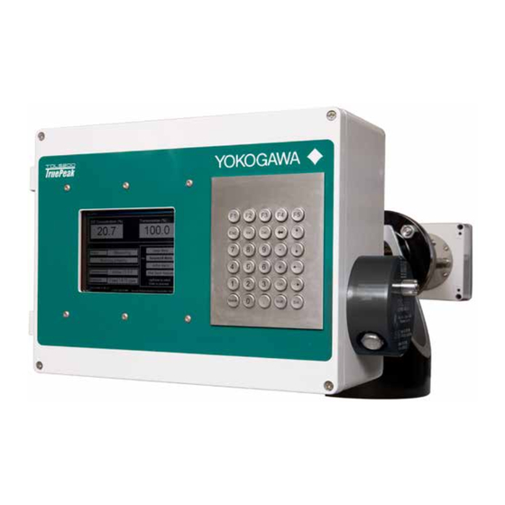
- Page 1 User’s TDLS200 Manual Tunable Diode Laser Spectroscopy Analyzer IM 11Y01B01-01E-A Yokogawa Corporation of America IM 11Y01B01-01E-A 2 Dart Road, Newnan, Georgia U.S.A. 30265 6th Edition Tel: 1-800-888-6400 Fax: 1-770-254-0928 Yokogawa Corporation of America...
- Page 2 Introduction Thank you for purchase the TDLS200 Tunable Diode Laser Analyzer. Please read the following respective documents before installing and using the TDLS200. Notes on Handling User’s Manuals • This manual should be passed on to the end user. • The contents of this manual are subject to change without prior notice.
- Page 3 Warning and Disclaimer The product is provided on an “as is” basis. YOKOGAWA shall have neither liability nor responsibility to any person or entity with respect to any direct or indirect loss or damage arising from using the product or any defect of the product that YOKOGAWA cannot predict in advance.
- Page 4 ALL POTENTIAL ACCIDENTS. AVOID SHOCK AND IMPACT TO THE ANALYZER THE LASERS CAN BE PERMANENTLY DAMAGED Laser Safety & Classification according to FDA Regulations. The TDLS200 is Registered with the United States FDA as a Laser Product.
- Page 5 Warning and Disclaimer The product is provided on an “as is” basis. YOKOGAWA shall have neither liability nor responsibility to any person or entity with respect to any direct or indirect loss or damage arising from using the product or any defect of the product that YOKOGAWA cannot predict in advance.
-
Page 6: Table Of Contents
TOC-1 TABLE Of CONTENTS Introduction ................................i Safety Precutions ............................... ii Quick Start ..............................1-2 Introduction and General Description ....................2-1 2.1 Functional Description ........................2-1 2.1.1 Measurement ..........................2-2 2.2 Instrument Check ..........................2-2 General Specifications ..........................3-1 3.1 Model & Suffix Code ..........................3-4 Analyzer Components ..........................4-1 4.1 Launch Unit ............................4-2 4.2 Main Electronics Housing ........................4-3 4.3 Laser Assembly ...........................4-6... - Page 7 TOC-2 6.6 Valve Control Logic ...........................6-30 6.7 Introduction for H Oppm measurements in Methane Gas ...............6-32 6.8 Introduction to Gas Temperature Predictions with High Temperature Oxygen Measurements ..6-38 6.9 Controlling the Analyzer Remotely or Locally via external PC/Laptop2 ...........6-34 6.9.1 Instructions for Connecting an External Computer to the Analyzer ...........6-35 6.9.2 Using Ultra-VNC Software ......................6-36 6.9.3 Remote Interface Unit (RIU) ......................6-37 6.9.4 Virtual Analyzer Controller (VAC) Operating Software Map ............6-37...
-
Page 8: Quick Start
– Failure to do so can result in serious damage to the TDLS200 or contamination to the internal optical elements. Connect the appropriate analyzer purge gas (nitrogen for oxygen analyzers) and make site connections per the supplied purge gas sequence details (including any Hazardous area purge system). - Page 9 Introduce some measured gas into the optical path and re-start or perform a validation with target gas. This will ensure that the analyzer is correctly tuned to the measurement gas absorption peak. If this Warning cannot be cleared by either method, please contact Yokogawa Laser Analysis Division or your local agent for further assistance.
- Page 10 If there is any doubt about any aspect of the Instrument or its use, please contact Yokogawa Laser Analysis Division and/or your authorized Representative/Distributor.
-
Page 11: Introduction And General Description
<2. INTRODUCTION AND GENERAL DESCRIPTION> 2-1 2 INTRODUCTION AND GENERAL DESCRIPTION The TDLS200 TDLS analyzer is designed to measure 2.1 functional Description selected target gases in gas phase samples directly at the process point (across stack, across pipe, Tunable Diode Laser Spectroscopy (or TDLS) etc.), close coupled/by-pass leg or in full extractive... -
Page 12: Measurement
Upon delivery, unpack the instrument carefully and inspect it to ensure that it was not damaged during shipment. If damage is found, retain the original packing materials (including the outer box) and then immediately notify the carrier and the relevant Yokogawa sales office. TDLS Analyzer... - Page 13 For products used within the European Community or other ries requiring the CE mark and/or ATEX classification, the ing labels are attached (as appropriate): <2. INTRODUCTION AND GENERAL DESCRIPTION> 2-3 For Zone 2 (CAT 3) ATEX use the following labels will be attached as appropriate: For YR-200 (Remote Interface Unit, RIU) Zone 2 (CAT 3) ATEX use the following labels will be attached as appropriate: IM 11Y01B01-01E-A...
- Page 14 <the l ines s hould b e a r ed c olor a nd t hickness h ere, s ee e xample p hoto o f F LXA21 I M b elow> ...
- Page 15 <2. INTRODUCTION AND GENERAL DESCRIPTION> 2-5 Maintenance Work by Qualified Personnel Unqualified work on the product may result in severe personal injury and/or extensive damage to property. If the Warnings contained herein are not adhered to the result may also be severe personal injury and/or extensive damage to property.
-
Page 16: General Specifications
<3. GENERAL SPECIFICATIONS> 3 GENERAL SPECIfICATIONS 3G with purge system EEx pz II T5 Class 1 Div.2 Group BCD with integral purge KC mark: KCC-REM-YCA-EEN999 0.5A@125 VAC USB1 and USB2 connection for data transfer using memory stick, data storage in CF card (result files, spectra capture, configuration data, etc.) Capture rate is configurable typical capacity for results and spectra is 14 days. - Page 17 IEC 61508 or EN 954-1. Functional Safety of Electrical/ inlet electronic/programmable electronic related systems; SIL 1 capability for single device. * The TDLS200 is not SIL certified as standard; to be certified the unit Span check gas. Zero check gas, at grade...
- Page 18 <3. GENERAL SPECIFICATIONS> Standard Accessories Display and Software functions Calibration Cell: - Used for off-line calibrations and TruePeak Software has multiple levels, the default (or start page) is validations the Main Menu: - Stainless steel 316 with free standing frame Main Menu Displays: - Concentration &...
-
Page 19: Model & Suffix Code
<3. GENERAL SPECIFICATIONS> 3.1 Model and Suffix Codes Model Suffix Code Option Code Description TDLS200 -------------------------------------------- ---------------------------- Tunable Diode Laser Type ---------------------------- General Purpose (None CE) ---------------------------- General Purpose (CE/KC) ---------------------------- Class I Div 2 BCD Purged ---------------------------- ATEX CAT 3/ zone 2 Purged, KC... -
Page 20: Analyzer Components
<4. ANALYZER COMPONENTS> 4 ANALYZER COMPONENTS Launch Unit: Launch Unit: Detect Unit: TDLS200 TDL Analyzer Instruction Manual V2.1 • Main Electronics Housing • Analyzer detachable from process • Detect Electronics • User Interface (optional) interface for Off-Line calibration / service. -
Page 21: Launch Unit
<4. ANALYZER COMPONENTS> 4.1 Launch Unit Main Electronics Housing • Back Plane circuit board • Single Board Computer (SBC) • FPGA signal Processing board • Analog I/O circuit board Check Gas Flow Cell • Field electrical terminals are located on Back Plane Short cell (gas tight chamber) (and optional Analog I/O board). - Page 22 <4. ANALYZER COMPONENTS> 4.2 Main Electronics Housing Enclosure Die cast copper free aluminum grade AL Si 12 alloy (A413.0) with a powder coat exterior finish. The copper free aluminum alloy is particularly resistant to salt atmospheres, sulfur gases and galvanic corrosion. An externally hinged door opening to the left incorporates a weather tight gasket seal and four captive fastening screws (stainless steel).
- Page 23 <4. ANALYZER COMPONENTS> Watchdog Power Interrupts The power output channels for microprocessors have control logic lines (TTL activated). These allow for watchdog interrupt/reset functionality. Alarm Relays There are three alarm relay circuits on the board. These are capable of actuating Form C Single Pole Double Throw (SPDT) relays.
- Page 24 <4. ANALYZER COMPONENTS> Connections of each relay (Common and Normally Open) are routed through the board to field terminals. The contacts are rated for a maximum of 1A @ 24VDC (or 0.5A @ 125VAC). The pluggable field terminals are mounted on the lower edge of the board, just to the left side of the DC power input terminals.
-
Page 25: Laser Assembly
<4. ANALYZER COMPONENTS> Optional Mini Display (4x20 VFD) mounts on the analyzer enclosure door. The display itself is an indus- trial grade 4 line 20 character vacuum fluorescence display (VFD) that is self illuminating (i.e. no back light required). Optional 6.5” Display is an industrial grade 6.5” VGA color TFT LCD Module that has a built-in CCFL backlight. -
Page 26: Check Gas Flow Cell (For On-Line)
Please also refer to project specific drawings for detail of how to configure the tubing/valving when implementing line locking. The various parameters that enable the validation are all configurable within the TDLS200 software. Refer to the Validation and Calibration section of this User Guide for further details. -
Page 27: Detect Unit
<4. ANALYZER COMPONENTS> 4.5 Detect Unit Detect unit Detect Electronics Housing • Detector Circuit Board Detect Electronic Process Interface Housing Detect Assembly Detector Housing and Detector Module • Detector and focusing lens assembly • Detector module designed to be field replaceable and purged to prevent ambient air ingress. -
Page 28: Process Interface
the maximum temperature reading is monitored. The board is medium size (approx. 4” H x 6” W) printed circuit board that mounts inside the enclosure. The field terminations are located along the lower edge of the board via pluggable <4. ANALYZER COMPONENTS> terminal block. -
Page 29: Analyzer Connections
<4. ANALYZER COMPONENTS> 4-10 4.7 Analyzer Connections Launch – Detect Interconnect The two units are connected to each other via a four, twisted pair cable suitable for tray installation outdoors. Pluggable terminals strips are provided at both units to enable field termination of the cable. The cable pairs are individually shielded as well as an overall shield. -
Page 30: Communications
<4. ANALYZER COMPONENTS> 4-11 4.8 Communications Stand Alone Options The analyzer is capable of fully independent operation with no external computer or interface required. A number of options are available for a built in user interface (mounted on Launch Unit): •... - Page 31 TDLS200 TDL Analyzer Instruction Manual V2.1 <4. ANALYZER COMPONENTS> 4-12 The unit acts as a remote interface for the analyzer. Should the physical location of the actual analyzer(s) be inconvenient for easy access, then the RIU can be used. The unit acts as a remote interface for the analyzer. Should the physical location of the actual analyzer(s) be inconvenient for easy access, then the RIU can be used.
-
Page 32: Purge
4.9 Purge Systems The purge gas may be either Instrument Air or Nitrogen. The TDLS200 Analyzer requires a continuous nitrogen gas purge to prevent ambient oxygen ingress to the opti- 2.3.10 Purge Systems cal path, when oxygen is the measured gas. The flow rate can be minimized as long as it prevents any ambient oxygen ingress to the measurement optical path. - Page 33 <4. ANALYZER COMPONENTS> 4-14 TDLS200 TDL Analyzer Instruction Manual V2.1 TDLS200 TDL Analyzer Instruction Manual V2.1 Purging Analyzer for Safe Area. The block diagram below shows the sections of the analyzer that require nitrogen purging. The purging should Purging Analyzer for Safe Area Purging Analyzer for Safe Area be carried in sequence typically as shown below.
-
Page 34: Installation And Wiring
5 INSTALLATION AND WIRING Detailed Installation, Wiring, Utility Drawings are included on a Project Basis. Please contact Yokogawa for any project specific documentation to ensure correct installation. Drawings provided herein are considered for standard installation use only 5.1 Process Measurement Point Considerations... -
Page 35: Position Of Process Flanges For Launch And Detect Units
TDLS200 TDL Analyzer Instruction Manual V2.1 <5. INSTALLATION AND WIRING> 5-2 3.2 Position of Process Flanges for Launch and Detect Units: Position of Process Flanges for Launch and Detect Units: Process flanges should be located on the process such that the Launch and Detect Units can be Process flanges should be located on the process such that the Launch and Detect Units can be installed, installed, accessed removed in a safe and convenient manner. -
Page 36: Process Flange Welding Alignment And Line-Up
Figure 21 - Reinforcing Plate for Launch or Detect Unit Flanges 3.3 Process Flange Welding Alignment and Line-Up All Rights Reserved. Copyright © 2011, Yokogawa Electric Corporation. Subject to change without notice. IM 11A00V01-01E-A January 2011... - Page 37 <5. INSTALLATION AND WIRING> 5-4 5.3 Process flange Welding Alignment and Line-Up Figure 21 - Reinforcing Plate for Launch or Detect Unit Flanges The Launch and Detect units are provided with alignment mechanisms that allow for some manual adjustment of the laser beam direction in both planes. It is however recommended that the following angular tolerances be 3.3 Process Flange Welding Alignment and Line-Up adhered to as closely as possible.
-
Page 38: Process Flange Clear Aperture
ALLOW FOR MINMUM 1.75” [45MM] CLEAR APERTURE. 3.5 Outlet Temperature Section .............7 refer to the instructions in this manual in All Rights Reserved. Copyright © 2011, Yokogawa Electric Corporation. Subject to change without notice. IM 11A00V01-01E-A January 2011 3.6 Self Acting Temperature Controller ..........7 order to prevent the instrument (hardware) BEST INSTALLATION WILL HAVE NO LATEAL OFFSET. -
Page 39: Process Window Purge Gas Connection
<5. INSTALLATION AND WIRING> 5-6 5.5.1 Process Window Purge Gas Connection In order to keep the process windows clean (prevent fouling by process gas) it is necessary to purge the windows with a clean dry gas of sufficiently low dew point. When measuring Oxygen, Nitrogen should be used for purging the windows. -
Page 40: Typical Purge Gas Configuration, In-Situ
<5. INSTALLATION AND WIRING> 5-7 5.7 Typical Purge Gas Configuration, In-Situ Please refer to project specific details, the following is a typical standard in-situ configuration: Figure 30 5.8 Typical Purge Gas Configuration, Extractive trace ppm H2O system: Please refer to project specific details, the following is a typical standard enhanced flow cell configuration: Figure 31 IM 11Y01B01-01E-A 6th Edition :Feb 13, 2013-00... -
Page 41: Dimensional Drawings
<5. INSTALLATION AND WIRING> 5-8 Typical Purge Large Aperture Optics (LAO) combustion O2, CO/CH4 Figure 32 5.9 Dimensional Drawings Figure 33 - General Installation Clearance Requirements IM 11Y01B01-01E-A 6th Edition :Feb 13, 2013-00... - Page 42 <5. INSTALLATION AND WIRING> 5-9 Figure 34 -Off-Line Calibration Overview Figure 35 - Launch and Detect unit Dimensions IM 11Y01B01-01E-A 6th Edition :Feb 13, 2013-00...
- Page 43 <5. INSTALLATION AND WIRING> 5-10 Figure 36 - Remote Interface Unit Figure 37 - Universal remote Display (URD) IM 11Y01B01-01E-A 6th Edition :Feb 13, 2013-00...
- Page 44 <5. INSTALLATION AND WIRING> 5-11 Figure 38 - Universal Power Supply (UPS) Figure 39 - Alignment Bellows * Other flange sizes available to meet application needs IM 11Y01B01-01E-A 6th Edition :Feb 13, 2013-00...
- Page 45 <5. INSTALLATION AND WIRING> 5-12 Figure 40 - Large Apenture * Other flange sizes available to meet application needs Figure 41 - Isolation Flanges, model IF200 IM 11Y01B01-01E-A 6th Edition :Feb 13, 2013-00...
- Page 46 <5. INSTALLATION AND WIRING> 5-13 Figure 42 - Insertion Tube Detail Figure 43 - Off-Line Calibration Gas and Purge Detail IM 11Y01B01-01E-A 6th Edition :Feb 13, 2013-00...
- Page 47 <5. INSTALLATION AND WIRING> 5-14 Figure 44 - Utility Panel Tubing Detail Standard Single, Auto - validation Figure 45 - Utility Panel Tubing Detail Standard Dual Auto - validation IM 11Y01B01-01E-A 6th Edition :Feb 13, 2013-00...
- Page 48 <5. INSTALLATION AND WIRING> 5-15 5.10 Wiring 5.10.1 Wiring of Launch for the US version Figure 46 IM 11Y01B01-01E-A 6th Edition :Feb 13, 2013-00...
- Page 49 <5. INSTALLATION AND WIRING> 5-16 5.10.2 Launch and Detect Unit Wiring – Standard for CE/ATEX SPECIAL NOTE: Noise sources magnetically coupled to the 4-pair launch to detect cable can cause errors to the measurement if the frequency and applied total voltage meet or exceed the following; Frequency range of 0.1 to 7.5 MHz and Total induced voltage of 3Vrms.
- Page 50 <5. INSTALLATION AND WIRING> 5-17 Launch and Detect Unit Wiring – Standard GP/Div2 (non CE/ATEX) Launch Unit (to Detect) Terminations at TB-7 Detect Unit (to Launch) Terminations at TB-13 IM 11Y01B01-01E-A 6th Edition :Feb 13, 2013-00...
- Page 51 <5. INSTALLATION AND WIRING> 5-18 5.10.3 Launch Unit Terminations CE/ATEX/GP/Div2 – all units: SEE FOLLOWING NOTES: Please NOTE that ALL analog output signals from TB-8 are POWERED BY THE ANALYER! Outputs from TB-9 can be configured for POWERED inputs or LOOP POWERED external transmitter! PLEASE CHECK CAREfULLY BEfORE APPLYING POWER TO THE ANALYZER! IM 11Y01B01-01E-A 6th Edition :Feb 13, 2013-00...
-
Page 52: Hazardous Area Systems
3.3 Steam Supplement ................6 3.3 Inlet Temperature Section ..............6 The TDLS200 Analyzer requires a continuous nitrogen or I/A gas purge to prevent ambient oxygen ingress to the WARNING optical path, when oxygen is the measured gas. The flow rate can be minimized as long as it prevents any ambient 3.4 Heat Exchanger Section ...............6-7... -
Page 53: Purging Analyzer For Hazardous Areas (With On-Line Validation)
The Purge Systems are not manufactured by Yokogawa Laser Analysis Division. <5. INSTALLATION AND WIRING> 5-20 3.9.1 Purging Analyzer for Hazardous Areas (with On-Line Validation) 5.11.1 Purging Analyzer for Hazardous Areas (with On-Line Validation) • Z-Purged designed in accordance with NEC/CSA Class 1, Division 2, Groups A-D •... -
Page 54: Purging Analyzer And Universal Power Supply And/Or Urd For Hazardous Areas (With On-Line Validation)
Figure 49 - Purge Flow Diagram when using on line validation Figure 29 - Purge Flow Diagram when using on line validation 5.11.4 Purging Analyzer and Universal Power Supply and/or URD (not using On-Line Validation) TDLS200 TDL Analyzer Instruction Manual V2.1 • NEC/CSA Class 1, Division 2, Groups A-D... - Page 55 <5. INSTALLATION AND WIRING> 5-22 5.12 Cyclops Division 2/Zone 2 Purge Indictor, with switch Type Z purging reduces the classification within a protected electronics enclosures from Division 2 or Zone 2 to nonhazardous. Failure to maintain pressure within the protected enclosure shall be detected by an alarm or indicator at the electronics enclosure.
- Page 56 <5. INSTALLATION AND WIRING> 5-23 Normal Operating Conditions Power Certified for installation and use in ATEX and IECEx for Type Z – Purge, II 3 G Ex nA nL [pz] IIC T6 For Zone 2 gas hazardous areas Manual Dilution Cycle Time To Typically, dilution cycle time is to ensure that at least five (5) Energizing Electrical Equipment times the volume of free space in the enclosure of protective...
-
Page 57: Basic Operations
<6. BASIC OPERATION> 6 BASIC OPERATION 6.1 Menu Structure Map Online Menu Level 1 Menu Level 2 Menu Level 3 Menu Level 4 Menu Level 5 Menu Basic MENU Select A/O Mode Configure Process Path Length -Block (mA value) -Track Pressure* -Hold Temperature*... - Page 58 <6. BASIC OPERATION> Online Menu Level 1 Menu Level 2 Menu Level 3 Menu Level 4 Menu Level 5 Menu Advanced Configure System I/O Analog Output Channel 1 Conc1/Conc2/Tran/Temp/Pres/ None * Password 4 mA- 20 mA Protected Channel 2* (Always uses track mode) Channel 3* Block Mode (mA value)
- Page 59 <6. BASIC OPERATION> Online Menu Level 1 Menu Level 2 Menu Level 3 Menu Level 4 Menu Level 5 Menu ADVANCED Configure Laser Spectra & Control Peak Width *Password Control Mode Manual Protected Automatic Max Current Current Laser Temp Set* *(similar to Max Current) Spectrum Capture LTSP Limits...
- Page 60 Validation Status Offline Validating… Online Validating… Data Transferring… Transfer Success Data Transfer Status Transfer Failure Yokogawa TDLS Analyzer Name SN 76-1xxx-05-xx Analyzer Serial No. AO1: CONC xx-xx%/ppm/ppb/mg/m3 Configured 4-20mA output for AO1, AO2, & AO3 or mg/Nm3 Static IP Address...
-
Page 61: Software Guide
<6. BASIC OPERATION> 6.2 Software Guide NOTE: At any time in the Main Menu, press the F5 key (only on Screen & Keypad versions) to toggle the LCD backlight on/off. If there is no keypad (or VNC) activity for 30 minutes then the LCD backlight will automatically switch off, press any key to restore backlight. - Page 62 <6. BASIC OPERATION> BASIC CONfIGURE PATH LENGTH – allows adjustment of the optical path (distance the laser is exposed to the process gas). PRESSURE – allows adjustment of the gas pressure value if using fixed pressure. If the analyzer is using active pressure compensation (live signal fed from pressure transducer) no changes are allowed.
- Page 63 <6. BASIC OPERATION> The BASIC DATA MENU allows the user to select: ALARM HISTORY – displays the last 17 alarms and faults with brief description, date and time CALIBRATION HISTORY - displays the last 17 calibration events with adjustment amount, date and time ...
- Page 64 Consider just the distance of process gas exposure to the laser beam path. Consult Yokogawa is any assistance required. For by- pass applications with window purges, typically the center line distance from inlet-outlet pipes is used. For combustion applications, the distance inside the refractory for example.
-
Page 65: Non-Process Parameters
Fixed value ACTIVE PEAKS is used for special high temperature oxygen combustion application when the gas is above 800˚C – used only when approved by Yokogawa and not functional <800˚C CONTROL is not used in TDLS-200 NON-PROCESS PARAMETERS... - Page 66 <6. BASIC OPERATION> 6-10 UNITS Path Length, select the appropriate units of measure for Path Length: in/ft/cm/m Pressure, select the appropriate units of measure for Pressure: psiA, barA, kPa, torr, atm Temperature, select the appropriate units of measure for Temperature: F, C, K ...
- Page 67 <6. BASIC OPERATION> 6-11 SYSTEM I/O - DIGITAL OUTPUT Setting of Digital Output assignments (DO 1-3) CHANNEL 1 WARNINGS – Setting of levels that will trigger analyzer warning and subsequent DO CHANNEL 2 FAULTS – Setting of levels that will trigger analyzer fault and subsequent DO CHANNEL 3 USER ALARM –...
- Page 68 On-Line Validation can be considered as Response Checking. Please consult Yokogawa for further information and help in determining what an appropriate Pass/Fail criteria is for the specific application. DO FAULT DELAY - this feature allows the end user to...
- Page 69 <6. BASIC OPERATION> 6-13 CHANNEL 3 - USER ALARMS Enables digital output alarm for concentration value (High or Low), Transmission (High or Low) or Validation/Calibration (the contact changes state during a validation or calibration) DIGITAL INPUT – STATUS CHECK The user can check the status of remote Digital Inputs ...
- Page 70 <6. BASIC OPERATION> 6-14 SYSTEM Some settings are not adjustable by user, user adjustment is possible for: PASSWORD – changes password for ADVANCED menu access DATE & TIME – changes analyzer date and time TCP/IP – the analyzers real IP address used for Ethernet communications can be changed via this menu option.
- Page 71 <6. BASIC OPERATION> 6-15 LASER SPECTRA & CONTROL Displays Raw Detector Signal and Absorption Spectrum as well as Gas Concentration, Gas Temperature, Gas Pressure, Transmission, Laser Temperature, Peak Center Position and other parameters CAPTURE – allows a manual spectra capture (user will be prompted to enter a unique file name for captured spectra) CONTROL MODE –...
- Page 72 <6. BASIC OPERATION> 6-16 OffLINE CALIBRATIONS ZERO CALIBRATION – manual or automatic calibration of Zero - ensure there is no absorption peak feature before performing a zero calibration, failure to do so can result is false low readings later when the un-desired target gas has been removed.
- Page 73 <6. BASIC OPERATION> 6-17 ONLINE VALIDATIONS CHECK GAS 1 – allows user to select and configure the on-line validations for check gas #1. The configuration options include Manual or Automatic. Automatic has selections for Local Initiate, Remote Initiate, Time Initiate as well as Settings for these options CHECK GAS 2 –...
- Page 74 6-18 6.3 Non-Process Parameters Non-Process Parameters is the Yokogawa Laser Analysis Division term used to define regions of the optical path that may be purged with a gas containing the actual target (measured) gas. The most common application of this is to use Instrument Air (~20.9% O...
- Page 75 It is important that these dimensions are known as they will need to be programmed in – if in doubt, please contact Yokogawa Laser Analysis Division.Calibration – The analyzer MUST be calibrated (Zero and Span) as per the normal methods outlined in the standard User’s Guide. When performing a Zero Calibration, ensure that the entire optical path is purged with Nitrogen.
- Page 76 This is the pressure of the non-process gas. Typically, this will be close to atmospheric pressure of 1.01 BarA or 14.7 PsiA. Check the actual operating conditions and enter the appropriate value. Contact Yokogawa if unsure. IM 11Y01B01-01E-A 6th Edition :Feb 13, 2013-00...
- Page 77 (typically -5 deg C) and an adjustable coefficient value (1.0 shown left). To derive the optimum coefficient value, please contact Yokogawa with installation and application details. This will ensure the optimal coefficient value taking into account the temperature gradient from ambient to process gas temperature for the non-process purge gases.
- Page 78 absorption peak near the measured absorption peak as the reference. This is used when the measured gas concentration is normally zero or very low such that its absorption peak is not large enough for the wavelength locking function. The adjacent absorption peak level, however, is <6.
- Page 79 <6. BASIC OPERATION> 6-23 Following pages are the various “Laser Spectra & Control” screen captures that depict the different scenarios depending on what process gas(es) are present in the OPL and what gas is purged through the analyzer: Following pages are the various “Laser Spectra & Control” screen captures that depict the different scenarios Note that the actual magnitude of the absorption units (au) as indicated on the “Absorption depending on what process gas(es) are present in the OPL and what gas is purged through the analyzer: Spectrum”...
- Page 80 On-Line Process Conditions – Analyzer Purged with Nitrogen: On-Line Process Conditions – Analyzer Purged with Nitrogen: <6. BASIC OPERATION> 6-24 TDLS200 TDL Analyzer Instruction Manual V2.1 Process OPL: Measured and Reference gas Process OPL: Measured and Reference gas On-Line Process Conditions – Analyzer Purged with Nitrogen:...
- Page 81 <6. BASIC OPERATION> 6-25 On-Line Process Conditions – Analyzer Purged with Nitrogen: When purging with Instrument Air (as opposed to ambient air), the H O levels are much smaller (due to it having been dried and having a dew point typically in the order of -40˚C) and therefore the H concentration is not large enough to produce an absorption peak that can be seen.
-
Page 82: Large Aperture Optics
The general concept of diverging beam and large aperture optics is shown below: Figure 52 In a standard TruePeak TDLS200 analyzer, the laser beam exiting the launch unit is normally collimated parallel before hitting the opposing detect unit. The collimated beam size is typically less than 1” diameter. However, this optical layout is not appropriate for long-path applications (the dimension of process is longer than 30 feet). - Page 83 The alignment of the Large Aperture Optics (or LAO) is quite similar to the alignment method of a standard TDLS200. To prepare for the alignment you will need some form of screen at the analyzer this can be a launch unit with a screen and keypad, a mini display, or a laptop PC connected through VNC/Ethernet.
- Page 84 RESISTOR BAG For a TDLS200 analyzer with diverging laser beam configuration (either with or without large aperture detector lens), a resistor bag is attached inside the detector box. The resistor bag contains the resistors with the following values. All of them are ¼ W, 5% tolerance metal film through-hole resistors.
- Page 85 If the current R22 value is same as the current R23 value, change R22 to the next greater value available in the resistor bag. iii. If the current R22 and R23 are already 24kΩ (the greatest value available in the resistor bag), please contact Yokogawa for assistance. IM 11Y01B01-01E-A 6th Edition :Feb 13, 2013-00...
-
Page 86: Dector Gain Adjustment Service Tips
STEP 8-a, and then optimize the alignment again. 6.6 Valve Control Logic The TDLS200 has three valve driver outputs (24VDC, 11W max each) available at Launch unit connection terminal TB-3. those can be used for calibration/validation functions and/or stream switching functions if being used in an extractive installation. - Page 87 • The remote initiate contacts are found at TB-2 and the external contact MUST BE VOLTAGE FREE. The TDLS200 circuits are low level current monitoring so any externally applied voltage/current may cause damage to the analyzer, hence use voltage free contact only.
-
Page 88: Introduction For H Oppm Measurements In Methane Gas
TDLS200 by using a special (previously proven) approach to spectroscopic data processing. However, reliability of results relies on stable and well defined conditions in the flow cell of the TDLS200 analyzer. Note that typically temperature of the process/calibration gases within the flow cells is to be maintained at 50.0±0.5 ºC and the gas pressure controlled at 30±0.25 psig. -
Page 89: Introduction To Gas Temperature Predictions With High Temperature Oxygen Measurements
<6. BASIC OPERATION> 6-33 Normal Operation – TDLS200 TruePeak Software Main Menu The analyzer is configured to measure not only H O ppm but it will also indicate the CH % concentration value, as shown on the Main Menu display below: Note that the flow... -
Page 90: Controlling The Analyzer Remotely Or Locally Via External Pc/Laptop2
• Remote control of the analyzer via TDLS200 software allows full control of the analyzer. The user will see the same screen with the same access functions as if controlling using a built in keypad and display. -
Page 91: Instructions For Connecting An External Computer To The Analyzer
The analyzer is provided with a CD that includes the VNCviewer program. Windows 7 will support the Ultra- VNC software and associated functionality. Contact your local Yokogawa agent for a free copy of the necessary “VNCviewer.exe” file that will enable the VNC connection with the analyzer. This VNCviewer.exe file should be loaded on to the connecting PCs desktop ready for use when connecting with the analyzer. -
Page 92: Using Ultra-Vnc Software
<6. BASIC OPERATION> 6-36 TDLS200 TDL Analyzer Instruction Manual V2.1 6.9.2 Using Ultra-VNC Software TDLS200 TDL Analyzer Instruction Manual V2.1 4.8.2 Using Ultra-VNC Software Start the Ultra-VNC software by double-clicking on the “vncviewer.exe” ICON (as shown below): Start the Ultra-VNC software by double-clicking on the “vncviewer.exe” ICON (as shown below): TDLS200 TDL Analyzer Instruction Manual V2.1... -
Page 93: Remote Interface Unit (Riu)
<6. BASIC OPERATION> 6-37 6.9.3 OPTIONAL Remote Interface Unit (RIU) The OPTIONAL RIU runs the Virtual Analyzer Controller (VAC) software described below. 6.9.4 Virtual Analyzer Controller (VAC) Operating Software Map IM 11Y01B01-01E-A 6th Edition :Feb 13, 2013-00... -
Page 94: Virtual Analyzer Controller (Vac) Operating Software Guide
<6. BASIC OPERATION> 6-38 6.9.5 OPTIONAL Virtual Analyzer Controller (VAC) Operating Software Guide ALWAYS “END VNC SESSION” TO ANALYZER WHEN DONE – THIS WILL PREVENT THE ANALYZER AND/ OR RIU fROM ‘HANGING’. DO NOT LEAVE THE RIU PERMANENTLY CONNECTED TO ANALYZER – CONNECT ONLY WHEN IN USE 6.9.6 Virtual Analyzer Controller (VAC) Operating Software Guide... - Page 95 <6. BASIC OPERATION> 6-39 After selecting “Configuration – F4” you will be asked to Enter Password – the default password is 1234, then press F2 to proceed and then you will be allowed to select the analyzer (with description and IP address) you wish to configure. ...
- Page 96 <6. BASIC OPERATION> 6-40 To shut down the RIU, press the Esc key and the screen will appear as shown. Press 9 to continue with the shut-down process and when the RIU screen turns white, the power can be switched off. Note, there is no watch-dog in the RIU so un-like the TDLS-200, it will not automatically re-start after a period of time if power is not switched off.
-
Page 97: Routine Maintenance
<7. ROUTINE MAINTENANCE> 7 ROUTINE MAINTENANCE The TDLS200 TDL analyzer requires little routine maintenance if it has been installed, set-up and calibrated correctly. This section will outline the routine maintenance procedures. Maintaining Good Transmission The % Transmission of the laser light through the process is the most important variable to consider for routine maintenance and troubleshooting. - Page 98 HF or other similar corrosive gas. Window surface to be cleaned Figure 32 - Window Cleaning Figure 56 - Window Replacement TDLS200 TDL Analyzer Instruction Manual V2.1 O- ring correctly O-ring correctly seated in position seated in position Offset screw position...
- Page 99 <7. ROUTINE MAINTENANCE> 7.1.2 Replacing Windows If the windows are contaminated they may be cleaned using the following procedure: • If the analyzer has not yet been shut down, then please shut-down the analyzer properly and remove power to ensure the laser if OFF •...
-
Page 100: Alignment
7.3 Data Reporting, Storage and Retrieval 5.3 Analog Signal Field Loop Check The TDLS200 analyzer has been designed with extensive data reporting capabilities. All data is available in the analyzer as a text file for import into a spreadsheet for analysis 1. - Page 101 <8. VALIDATION AND CALIBRATION> 8 Validation and Calibration There are several methods that can be used to validate and/or calibrate the TDLS200 analyzer. Generally, we recommend routine validation of the analyzer either on-line (if appropriately set-up) or off-line. when the process gas can be isolated from the optical path (such as extractive enhanced flow cell).
- Page 102 <8. VALIDATION AND CALIBRATION> Please note that you can select the block mA value for automatic Off-Line Zero Calibration, Off-Line Span Calibration, Off-Line Validations and On-Line Validations: 8 .1 Off-Line Manual/Automatic Checking and Off-Line Calibration To perform either “Offline Calibrations” or “Offline Validations”, the Launch unit and Detect unit need to be removed from their respective process interface and connected to an Off-Line Calibration Cell.
-
Page 103: Validation And Calibration
<8. VALIDATION AND CALIBRATION> Moving the analyzer to the off-line calibration cell: If the process gas is at a positive pressure, Isolate the analyzer from the process and shut-off the window purge gas flow to prevent excessive pressure building up on the window. If the process is at or near negative pressure then be aware that ambient air will be drawn in to the process/stack when the analyzer is removed from its interface. - Page 104 <8. VALIDATION AND CALIBRATION> Procedure for Alignment Optimization on Calibration Cell 1. The launch unit should be adjusted so that the transmission is maximized for off-line calibration 2. Ensure launch unit alignment nuts are securely fastened so that the launch unit cannot move it’s alignment position 3.
- Page 105 FPGA board). If the Zero reading appears incorrect, then ensure all data results and spectra have been stored and send the files to Yokogawa Laser Analysis Division for further evaluation. Apply zero gas using the appropriate gas flow path as show:...
- Page 106 (indicating that the zero gas had not fully purged the optical path). Perform the zero calibration again in either case or check with your local Yokogawa representative. If there is reason to restore either zero calibration, then please follow the on-screen instructions: When an acceptable zero has been established, arrange the purge tubes as shown below and then follow the on-screen instructions for Span calibration.
- Page 107 9 to actually perform the calibration or escape to cancel. Note, the concentration that is being displayed and up-dated in the lower box is the currently measured value before the calibration is performed. After calibration, please check the results and consult with Yokogawa if any questions or concerns.
- Page 108 <8. VALIDATION AND CALIBRATION> If there is reason to restore either a Span calibration, then please follow the on-screen instructions: For Automatic Off-Line Calibrations, used only on extractive applications please follow the on-screen instructions: IM 11Y01B01-01E-A 6th Edition :Feb 13, 2013-00...
- Page 109 <8. VALIDATION AND CALIBRATION> IM 11Y01B01-01E-A 6th Edition :Feb 13, 2013-00...
- Page 110 <8. VALIDATION AND CALIBRATION> 8-10 MANUAL OffLINE VALIDATIONS Enter into the Advanced Menu, Calibrate & Validate section, Off-Line Validations. Choose Check gas 1, 2 or two gas validation and select Manual Validation. Following the on screen directions, enter in the pressure, temperature, cell length, & concentration of the gas within the off-line line check gas flow cell.
- Page 111 <8. VALIDATION AND CALIBRATION> 8-11 MANUAL OffLINE VALIDATIONS Enter into the Advanced Menu, Calibrate & Validate section, Off-Line Validations. Choose Check gas 1, 2 or 3 and select Manual Validation. AUTOMATIC OffLINE VALIDATIONS The Validations may be for Gas 1, Gas 2 or Two Gas Validation (such as Zero &...
- Page 112 <8. VALIDATION AND CALIBRATION> 8-12 There are several critical parameters that must be preconfigured in the TDLS200 software when using the automatic validation sequence. These parameters MUST be correctly set otherwise the analyzer will report false/incorrect validation results. • Check Gas Concentration specifies the concentration (ppm or %) of the gas within the offline flow cell.
-
Page 113: Off-Line Calibration For Reference Peak Lacking Application
<8. VALIDATION AND CALIBRATION> 8-13 8.2 Off-Line Calibration for Reference Peak Locking Applications: Zero and Span calibrations MUST be performed as per normal off-line procedures, without using and Reference Line locking gases. Process/Calibration OPL: N2 Analyzer Purge: N2 This is how the absorption spectra will appear when there is neither NH3 nor H2O (or any other target gas for the given application) in the entire optical path (Process OPL and Analyzer Purge). -
Page 114: On-Line Validation
<8. VALIDATION AND CALIBRATION> 8-14 8.3 On-Line Validation The basic concept of on-line validation is to add a known gas concentration via an integral check gas flow cell while still measuring the process gas concentration under relatively controlled conditions. The controlled (or known) conditions for the addition of the validation (or check) gas are: •... - Page 115 Raw Detect Signal, No Oxygen present Raw Detect Signal – Oxygen Present The TruePeak TDLS200 uses the raw detector signal to produce the actual absorption spectra (see below, note the vertical scale in Absorbance Units is different between the two spectra) which is then used to calculate the peak area.
- Page 116 Right On-Line Validation; By knowing the above measurement Baseline Absorption Baseline principles it is possible to understand that the TDLS200 is Region Region Region capable of performing on-line validations to verify analyzer measurement performance. When the analyzer is initially calibrated off-line using protocol certified gas standards, the area of the absorption peak is assigned a calibration coefficient.
- Page 117 <8. VALIDATION AND CALIBRATION> 8-17 A validation cycle consists of first capturing a process gas only spectra (1), then adding the validation gas to the validation cell and capturing a spectra (2) and then removing the validation gas and finally capturing a second process gas only spectra (3).
-
Page 118: Performing Manual Online Validation
<8. VALIDATION AND CALIBRATION> 8-18 8.5 Performing Manual OnLine Validation This will require the appropriate valves, tubes and tubes fittings such that the integral on-line check gas flow cell can be purged with either normal purge gas (typically Nitrogen) or the check gas (instrument air is acceptable for Oxygen analyzers in most applications). - Page 119 <8. VALIDATION AND CALIBRATION> 8-19 TDLS200 TDL Analyzer Instruction Manual V2.1 Enter in the temperature of the gas within the on-line line check gas flow Following the on screen directions, enter in the pressure of the cell. gas within the on-line line check gas flow cell. Typically this...
- Page 120 <8. VALIDATION AND CALIBRATION> 8-20 Wait for the reading to stabilize. Many processes are dynamic but judge for yourself when you believe the check gas has fully purged the integral check gas flow cell – typically at least one minute depending on the location of the switching valve.
-
Page 121: Performing Automated On-Line Validation
<8. VALIDATION AND CALIBRATION> 8-21 If the validation fails, repeat the validation after checking the parameters are correct and ensuring there is sufficient purge gas time. If the failure is due to a known non-related event (such as incorrect validation gas value or non-functioning valve) then the validation alarm can be cleared as shown. - Page 122 <8. VALIDATION AND CALIBRATION> 8-22 vent Analyzer Purge Online-Check Gas Gas Inlet Flow Cell Inlet TYP <2LTS/min Max 3 psig TYP <2LTS/min Figure 63 - Automated On-Line Validation (electric solenoid valve) vent Analyzer Purge Online-Check Gas Gas Inlet Flow Cell Inlet TYP <2LTS/min Max 3 psig TYP <2LTS/min...
- Page 123 Validation sequence based on a user configurable timed basis. • URD & Laptop PC with VAC software – The TDLS200 software allows for the user through a laptop PC running VAC software to initiate the Auto Validation sequence. The operator would be at the URD with the laptop PC plugged in to the Ethernet port on the URD Feed Through board.
- Page 124 Settings for Validation: Settings for Validation: There are several critical parameters that must be preconfigured in the TDLS200 software when using the automatic validation sequence. These parameters MUST be correctly set otherwise the analyzer will report There are several critical parameters that must be preconfigured in the TDLS200 false/incorrect validation results.
- Page 125 <8. VALIDATION AND CALIBRATION> 8-25 • Check Gas Pressure specifies the pressure at which the gas within the online line check gas flow cell. Typically this cell is vented to atmosphere so an atmospheric pressure value (14.7 psiA or 1.01barA) will work. •...
- Page 126 <9. TROUBLE SHOOTING> 9 TROUBLESHOOTING The TDLS200 Analyzer troubleshooting is fairly simple for a process analyzer. First, virtually all components used in the system have a long Mean Time Between Failures (MTBF) with rated life of components typically exceeding 15 years (when operating within their stated specifications). Second, most probable failures and problems are diagnosed by the system, generating internal warning and fault conditions.
-
Page 127: Troubleshootin
<9. TROUBLE SHOOTING> 9.1 Common Troubleshooting Steps For most conditions the troubleshooting steps are common. In general, the most common issues with the analyzer revolve around ensuring an adequate amount of the laser light is received at the detector. Check Status LEDs. This will ensure that power is routed properly to the system •... - Page 128 During this step, manually record the amount of analyzer reading change. detector. • Record Results. Download data files from the analyzer for e-mail to Yokogawa. • SPECIAL NOTE – Parts removal (if necessary) should be done so with great care! There are electrostatic sensitive devices (such as the Laser Diode Module!) that can be damaged if not handled correctly.
- Page 129 TDLS200 TDL Analyzer Instruction Manual V2.1 <9. TROUBLE SHOOTING> Resolving Low Transmission: Above – Good Launch and Detect Alignment Above – Poor Launch Unit Alignment Above – Poor Detect Unit Alignment Figure 65 - 110 - Page 110 of 131...
- Page 130 <9. TROUBLE SHOOTING> Alignment Adjustment a. Sometimes the original mechanical alignment of the analyzer may change due to mechanical/ thermal properties of the installation or perhaps the alignment nuts not being fully tightened originally. In these situations the analyzer can simply be realigned. b.
- Page 131 <9. TROUBLE SHOOTING> Figure 66- Insertion tubes, with insulation - materials, dimensions, etc. are specified to suit each different application lf possible to isolate the process flow through the measurement section of the process pipe/stack then proceed to shut it off accordingly to facilitate full, safe unrestricted access. c.
- Page 132 (laser source is inside launch unit body). i. Remove any obstructions in the nozzles in accordance with any local standards/procedures. If the obstructions are a re-occurring event, then please contact your local agent or Yokogawa for advice on how to prevent/reduce the events.
- Page 133 The following safety symbols are used on the product as well as in this manual. Please consult Yokogawa with specific information about the dust loadings within the process such that 1. Introduction ....................4 a proper evaluation can be made. If it is then determined that a reduction in optical path length will have...
-
Page 134: Field Up-Gradable Files And Software From Factory
If, after adjusting the direct angle between the two units there is still no transmission then the laser diode (and or detector) has failed. Please contact Yokogawa Laser Analysis Division for further assistance and information pertaining to Laser Module replacement. If a weak signal is achieved then this is an indication that the laser module has weak output power. -
Page 135: Analyzer Faults
Peak Center Out of Range. Indication that the system can not keep the peak centered in the scan range. Please review the absorption spectra to check the actual peak position, check that some target gas in the optical path – capture spectra and send to Yokogawa Laser Analysis Division or local agent for further assistance. - Page 136 All the files are stored in simple ASCII text format for easy importing to MS Excel spreadsheets (or other data manipulation software as appropriate). The rate at which data is captured may be configured from within the TDLS200 software. There are several files that are stored in the system:...
- Page 137 <10. Data Files anD Format> 10-2 Alarm History - in the form of ASCII data files that can be opened with Microsoft “Notepad” as simple .txt file formats. The content can then be copied and pasted into Alarms History alarms .his Microsoft Excel spread.
- Page 138 <10. Data Files anD Format> 10-3 calibr .pik Calibration Pick List - FACTORY PERSONNEL ONLY factory Use Only .dat Chemometric Model File Parent spectra for chemometric model used only for specialized applications that utilize the TruePeak CLS measurement capability. span00 .spe Span Calibration Spectra This file is essential to the analyzer calibration - if...
-
Page 139: Data Files And Format
<10. Data Files anD Format> 10-4 System Configuration History - When the system.his file exceeds 100KB size the contents is saved to this .bak file and the .his file is emptied. This .bak file is in the form of ASCII data files that can be opened with Microsoft “Notepad”... -
Page 140: Configuring Data Capture
<10. Data Files anD Format> 10-5 10.1 Configuring Data Capture: Select Data To select the Spectrum capture, stay in Advanced Menu user mode and the Data sub section – select Spectrum Capture To store spectrum automatically, select Automatic. If you do not wish to store any spectrum file during normal analyzer operation, then select Manual mode. - Page 141 <10. Data Files anD Format> 10-6 analyzer to capture spectrum files and under what condition. The default condition is related to the number of measurement however, the user can select Relative or Absolute changes pending the site specific conditions/ requirements.
-
Page 142: Downloading (Transfering/Exporting) The Data
Do not attempt to plug in any other USB based products (keyboards, WiFi, etc.) in to the USB ports – Windows based hardware conflicts may occur. – Windows based hardware conflicts may occur. Insert Yokogawa Supplied USB memory Storage Device Simply insert the memory device and wait for the Data Transfer to complete. - Page 143 Revision Record Manual Title: Model TDLS200 Tunable Diode Laser Spectroscopy Analyzer Manual Number: IM 11Y01B01-01E-A Edition Date Remark (s) April 2008 Newly Published April 2009 Revisions: Formatting was corrected. April 2010 Revisions: General specifications, page 3, were added to the document, and dimensional drawings were added.
- Page 144 Yokogawa has an extensive sales and Yokogawa Corporation of America North America distribution network. 2 Dart Road, Newnan, GA 30265-1094, USA Please refer to the website (www. Phone: 800-888-6400 Fax: 770-254-0928 yokogawa.com/us) to contact your nearest 12530 West Airport Blvd., Sugar Land, TX 77478 representative.
Need help?
Do you have a question about the TDLS200 and is the answer not in the manual?
Questions and answers