Advertisement
Quick Links
Installing and Configuring the Cisco Physical
Access Gateway
Contents
This chapter includes the following information:
•
•
•
•
•
•
•
OL-32499-01
Overview, page 2-2
Package Contents, page 2-3
Physical Overview and Port Description, page 2-3
Installing the Cisco Physical Access Gateway, page 2-7
Configuring and Managing the Gateway Using a Direct Connection, page 2-15
Understanding Network Time Protocol (NTP) Settings, page 2-15
–
Connecting a PC to the Gateway, page 2-16
–
–
Entering the Gateway Network Settings, page 2-17
–
Changing the User Password, page 2-19
–
Upgrading the Gateway Firmware Using a Direct Connection, page 2-20
Displaying Serial Numbers and Other Information, page 2-23
–
Configuring the Gateway Using the Cisco Physical Access Manager, page 2-24
Resetting the Cisco Physical Access Gateway, page 2-25
2
C H A P T E R
Cisco Physical Access Gateway User Guide
2-1
Advertisement

Related Manuals for Cisco CIAC-GW-K9


Summary of Contents for Cisco CIAC-GW-K9
- Page 1 Upgrading the Gateway Firmware Using a Direct Connection, page 2-20 Displaying Serial Numbers and Other Information, page 2-23 – Configuring the Gateway Using the Cisco Physical Access Manager, page 2-24 • Resetting the Cisco Physical Access Gateway, page 2-25 •...
- Page 2 The Gateway is connected to the Cisco Physical Access Manager using an Ethernet connection to the IP network. Power is supplied through a Power over Ethernet (PoE) connection, or using a DC power source. Each Gateway includes connections for up to two Wiegand door readers, three input devices, and three output devices.
-
Page 3: Package Contents
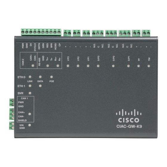
Figure 2-2 Figure 2-3 show the location of each port, including connections for power, Ethernet, door readers and other input and output devices. Figure 2-2 Cisco Physical Access Gateway Ports and Connectors: Side View Cisco Physical Access Gateway User Guide OL-32499-01... - Page 4 Modules are connected using the CAN1 interface. The CAN2 interface is not supported Note in this release. SVR (Server)—When the LED is steady green, the Gateway is connected to a Cisco PAM appliance. Fast Ethernet interfaces—There are two 10/100 BASE-TX RJ-45 connectors: •...
-
Page 5: Led Status
• C & NC connection: The relay is normally closed. The circuit is opened when triggered. Notes: Install surge protection between the output device and the Cisco PAM module, as described • in the “Installing Surge Suppressors on Output Device Connections” section on page 1-13. - Page 6 Chapter 2 Installing and Configuring the Cisco Physical Access Gateway Physical Overview and Port Description Table 2-1 Gateway LEDs (continued) Status Description Input Port LEDs Input is not configured GREEN Input is configured and in normal state BLINKING GREEN Input is configured, and is receiving and alarm or other data.
- Page 7 • Procedure, page 2-7 • Before You Begin Before you install a Cisco Physical Access Gateway, verify the following: Verify that the module has access to a power source. See the “Power Options and Requirements” • section on page 1-12 for more information.
- Page 8 Chapter 2 Installing and Configuring the Cisco Physical Access Gateway Installing the Cisco Physical Access Gateway Figure 2-4 Power Connections for the Cisco Physical Access Gateway DC power GND (ground)— Connects the DC ground wire to the Gateway. DC power Voltage In (VIN)—Connects the DC Voltage In (VIN) wire to the Gateway.
- Page 9 Chapter 2 Installing and Configuring the Cisco Physical Access Gateway Installing the Cisco Physical Access Gateway Figure 2-5 shows the location of the Wiegand interface connections. The table describes the connections for 10-pin and 5-pin reader interface connections. The wire connectors from the reader device are shown in parentheses.
- Page 10 (one terminator in each connector). Figure 2-6 shows the terminator installation for a Normally Closed (NC) and Normally Open (NO) input connection. Figure 2-6 Input Connections: Cisco Physical Access Gateway,Input and Reader Modules 1K,, 1% 1K,, 1% 1K,, 1% 1K,, 1%...
- Page 11 TM—Tamper input: an unsupervised input that raises a “tamper” alarm when the circuit is open. Can be configured as a general input device using the Cisco Physical Access Manager. An unsupervised input indicates only normal or alarm. The corresponding LED is red when circuit is open (when no input is connected).
- Page 12 Installing and Configuring the Cisco Physical Access Gateway Installing the Cisco Physical Access Gateway Figure 2-8 Output Connections: Cisco Physical Access Gateway and Reader Module Normally Open (N.O.) connection Normally Closed (N.O.) connection Connect optional expansion modules to the Gateway, if necessary:...
- Page 13 Chapter 2 Installing and Configuring the Cisco Physical Access Gateway Installing the Cisco Physical Access Gateway Figure 2-9 CAN1 Connections: Cisco Physical Access Gateway and Reader Module CAN+ Connects to the positive terminal of the CAN bus. CAN- Connects to the negative terminal of the CAN bus.
- Page 14 “Configuring and Managing the Gateway Using a Direct Connection” section on page 2-15 for more information. Step 8 Continue to the “Configuring the Gateway Using the Cisco Physical Access Manager” section on page 2-24. Cisco Physical Access Gateway User Guide 2-14...
- Page 15 Cisco Systems strongly recommends using a network time protocol (NTP) server to synchronize the date and time clock on each Gateway module, and on the Cisco PAM appliance. This ensures that events and messages between the server and the Gateway modules are in sync. If the time and date are not synchronized, inconsistent system behavior can occur.
- Page 16 You can use a DHCP server to assign an IP address for the Gateway. • If a DHCP server is not used, gather the Cisco Physical Access Gateway IP address, IP gateway, subnet mask. The domain name server (DNS) for the Gateway if DNS names (not IP addresses) are used for the •...
- Page 17 DNS Configuration: enter a DNS configuration if names (not IP addresses) are used for the NTP • or CPAM addresses. Cisco PAM Configuration: defines the IP address and port of the Cisco PAM appliance that is used • to manage the Gateway.
- Page 18 Enter the Cisco PAM IP Address (IP address or name) to enable Gateway communication with the appliance. Enter the Port number for the Cisco PAM appliance. The port number must be greater than 1024 and less 65535. The default is 8020.
- Page 19 Access Manager User Guide. Changing the User Password You can also change the password for one or more Gateways using the Cisco PAM desktop software. See the “Changing Gateway Passwords” section in the Cisco Physical Access Manager User Guide for more information.
- Page 20 Chapter 2 Installing and Configuring the Cisco Physical Access Gateway Configuring and Managing the Gateway Using a Direct Connection Procedure To change the password used to access the Gateway, perform the following procedure: Click the User Management tab, as shown in Figure 2-14.
- Page 21 Chapter 2 Installing and Configuring the Cisco Physical Access Gateway Configuring and Managing the Gateway Using a Direct Connection Procedure To upgrade the Gateway firmware from a PC directly connected to the module, perform the following procedure: Log on to the Gateway administration tool, as described in the “Connecting a PC to the Gateway”...
- Page 22 Delete configuration: delete the module configuration. The configuration is automatically – dowloaded when the Gateway establishes communication with the Cisco PAM appliance. Delete events: delete all events stored on the Gateway. – Click Upgrade to copy the firmware image to the Gateway module and perform the selected options (if Step 5 any).
- Page 23 “Connecting a PC to the Gateway” section Step 1 on page 2-16. Click the Show Inventory tab, as shown in Figure 2-16. Step 2 Figure 2-16 Show Inventory Window for the Cisco Physical Access Gateway Cisco Physical Access Gateway User Guide 2-23 OL-32499-01...
- Page 24 Configuring the Gateway Using the Cisco Physical Access Manager The serial number is also displayed on the back of the module. To view the serial number in Cisco PAM, open the Hardware module device view, right-click on the Gateway Controller, and choose Edit to view the module properties.
- Page 25 Hard Reset (Restore Factory Defaults), page 2-25 Soft Reset (Powercycle) Use the soft reset to powercycle the Cisco Physical Access Gateway. A soft reset reloads the device firmware to clear any software issues, but does not impact stored data. The password, logs and other information are retained.
- Page 26 Chapter 2 Installing and Configuring the Cisco Physical Access Gateway Resetting the Cisco Physical Access Gateway Cisco Physical Access Gateway User Guide 2-26 OL-32499-01...
Need help?
Do you have a question about the CIAC-GW-K9 and is the answer not in the manual?
Questions and answers