
Related Manuals for Cisco DPC3941T


Summary of Contents for Cisco DPC3941T
- Page 1 T P - 0 0 1 0 2 Cisco Model DPC3941T DOCSIS 3.0 24x4 Wireless Residential Voice Gateway User Guide...
- Page 3 Please Read Important Read this entire guide. If this guide provides installation or operation instructions, give particular attention to all safety statements included in this guide.
- Page 4 Cisco and the Cisco logo are trademarks or registered trademarks of Cisco and/or its affiliates in the U.S. and other countries. To view a list of Cisco trademarks, go to this URL: www.cisco.com/go/trademarks. DOCSIS is a registered trademark of Cable Television Laboratories, Inc.
- Page 5 Copyright © 2014 Cisco Systems, Inc. All rights reserved. Information in this publication is subject to change without notice. No part of this publication may be reproduced or transmitted in any form, by photocopy, microfilm, xerography, or any other means, or incorporated into any information retrieval system, electronic or mechanical, for any purpose, without the express permission of Cisco Systems, Inc.
- Page 6 Notice to Installers The servicing instructions in this notice are for use by qualified service personnel only. To reduce the risk of electric shock, do not perform any servicing other than that contained in the operating instructions, unless you are qualified to do so. Notice à...
- Page 7 Mitteilung für CATV-Techniker Die in dieser Mitteilung aufgeführten Wartungsanweisungen sind ausschließlich für qualifiziertes Fachpersonal bestimmt. Um die Gefahr eines elektrischen Schlags zu reduzieren, sollten Sie keine Wartungsarbeiten durchführen, die nicht ausdrücklich in der Bedienungsanleitung aufgeführt sind, außer Sie sind zur Durchführung solcher Arbeiten qualifiziert. Aviso a los instaladores de sistemas CATV Las instrucciones de reparación contenidas en el presente aviso son para uso exclusivo por parte de personal de mantenimiento cualificado.
-
Page 9: Table Of Contents
Contents IMPORTANT SAFETY INSTRUCTIONS United States FCC Compliance CE Compliance xiii About This Guide Chapter 1 Introducing the Residential Gateway Introduction ......................... 2 What's In the Carton? ......................4 Front Panel Description ...................... 5 Top Panel Desc ription......................7 Bottom Panel Desc ription ....................8 Back Panel Desc ription ....................... - Page 10 Contents Chapter 5 Maintaining the Battery Location of the Battery ...................... 44 Battery Maintenanc e ......................45 Chapter 6 Troubleshooting the Residential Gateway Frequently Asked Questions .................... 48 Common Troubles hooting Issues ..................54 Tips for Improved Performa nce ..................56 Chapter 7 Customer Information TP-00102...
-
Page 11: Important Safety Instructions
IMPORTANT SAFETY INSTRUCTIONS IMPORTANT SAFETY INSTRUCTIONS Read these instructions. Keep these instructions. Heed all warnings. Follow all instructions. Do not use this apparatus near water. Clean only with dry cloth. Do not block any ventilation openings. Install in accordance with the manufacturer's instructions. - Page 12 IMPORTANT SAFETY INSTRUCTIONS Outdoor Grounding System If this product connects to an outdoor antenna or cable system, be sure the antenna or cable system is grounded (earthed). This provides some protection against voltage surges and built-up static charges. Article 810 of the National Electric Code (NEC) ANSI/NFPA No. 70-1990, provides the following information: ...
- Page 13 IMPORTANT SAFETY INSTRUCTIONS Eliminate AC Power/Mains Overloads WARNING: Avoid electric shock and fire hazard! Do not overload AC power/mains, outlets, extension cords, or integral convenience receptacles. For products that require battery power or other power sources to operate them, refer to the operating instructions for those products.
-
Page 14: Operating Environment
IMPORTANT SAFETY INSTRUCTIONS Do not place entertainment devices (such as VCRs or DVDs), lamps, books, vases with liquids, or other objects on top of this product. Do not block ventilation openings. Operating Environment This product is designed for operation indoors with a temperature range from 32° to 104° F (0° to 40°C). Each product should have adequate spacing on all sides so that the cooling air vents on the chassis are not blocked. - Page 15 IMPORTANT SAFETY INSTRUCTIONS Telephone Equipment Notice When using your telephone equipment, basic safety precautions should always be followed to reduce the risk of fire, electric stock and injury to persons, including the following: 1. Do not use this product near water, for example, near a bath tub, wash bowl, kitchen sink or laundry tub, in a wet basement or near a swimming pool.
-
Page 17: United States Fcc Compliance
Consult the service provider or an experienced radio/television technician for help. Any changes or modifications not expressly approved by Cisco Systems, Inc., could void the user's authority to operate the equipment. The information shown in the FCC Declaration of Conformity paragraph below is a requirement of the FCC and is intended to supply you with information regarding the FCC approval of this device. - Page 18 United States FCC Compliance This system has been evaluated for RF exposure for humans in reference to ANSI C 95.1 (American National Standards Institute) limits. The evaluation was based in accordance with FCC OET Bulletin 65C rev 01.01 in compliance with Part 2.1091 and Part 15.27. The minimum separation distance from the antenna to general bystander is 7.9 inches (20 cm) to maintain compliance.
-
Page 19: Ce Compliance
This declaration is only valid for configurations (combinations of software, firmware and hardware) supported or provided by Cisco Systems for use within the EU. The use of software or firmware not supported or provided by Cisco Systems may result in the equipment no longer being compliant with the regulatory requirements. -
Page 20: National Restrictions
CE Compliance The following standards were applied during the assessment of the product against the requirements of the Directive 1999/5/EC: Radio: EN 300 328 EMC: EN 301 489-1 and EN 301 489-17 Safety: EN 60950 and EN 50385 The CE mark and class-2 identifier are affixed to the product and its packaging. -
Page 21: About This Guide
Model DPC3941T DOCSIS 3.0 24x4 Wireless Residential Voice Gateway (DPC3941T). Purpose This guide covers the Model DPC3941T DOCSIS 3.0 24x4 Wireless Residential Voice Gateway. All features described in this guide are standard to this Residential Gateway unless otherwise noted as an optional feature. -
Page 23: Chapter 1 Introducing The Residential Gateway
Chapter 1 Introducing the Residential Gateway Introduction This chapter provides an overview of Residential Gateway features, indicators, and connectors to help you become familiar with the Residential Gateway and the benefits it offers. This chapter also lists the accessories and equipment that are provided with the Residential Gateway so you can verify that you received all of these items. -
Page 24: Introduction
Connected Home and Managed Home experiences. This chapter lists the benefits and features of the model DPC3941T Residential Gateway. Illustrations and descriptions of the connection ports, buttons, and LED indicators are also provided. - Page 25 Introduction Design and Function Attractive, compact design and versatile orientation to stand vertically LED status indicators on the front panel, providing an informative and easy-to- understand display that indicates the operational status TR-068-compliant, color-coded interface ports and corresponding cables that ...
-
Page 26: What's In The Carton
The carton contains the following items: One AC power cord One Model DPC3941T Residential Gateway One Lithium Ion cartridge battery (May not be provided with all products.) -
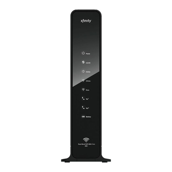
Page 27: Front Panel Description
Front Panel Description Front Panel Description The front panel of your Residential Gateway provides LED status indicators that indicate how well and at what state your Residential Gateway is operating. See Operation of Front Panel Indicators (on page 37), for more information on front panel LED status indicator functions. - Page 28 Chapter 1 Introducing the Residential Gateway —ON indicates telephony service is enabled. Blinks when line 1 is in use. OFF indicates that phone service for TEL 1 is not enabled. —ON indicates telephony service is enabled. Blinks when line 2 is in use. OFF indicates that phone service for TEL 2 is not enabled.
-
Page 29: Top Panel Description
Top Panel Description Top Panel Description Two buttons and LEDs on the top panel of the Residential Gateway show the status of the Wireless Protected Setup (WPS) and Page features. WPS (WIRELESS PROTECTED SETUP)—OFF (normal condition) Wireless Protected Setup is not active. Blinking indicates the button has been pressed and WPS is active so that a new wireless client can be added to the wireless network. -
Page 30: Bottom Panel Description
Chapter 1 Introducing the Residential Gateway Bottom Panel Description The bottom panel of your Residential Gateway contains a product information label and the door to the battery compartment. LABEL—product information label BATTERY—battery compartment door TP-00102... -
Page 31: Back Panel Description
Back Panel Description Back Panel Description The following illustration identifies the back panel components on the Cisco Residential Gateway. Descriptions for each component follow the illustration. Important: Do not connect your PC to both the Ethernet and USB ports (future capability) at the same time. - Page 32 Chapter 1 Introducing the Residential Gateway USB (optional)—Connects the Residential Gateway to selected devices. For models that support USB, the default is one USB port. TEL1 and Alarm/Tel2—RJ-11 telephone ports for connecting telephones, fax machines, and/or an analog home alarm system. ETHERNET—Four RJ-45 Ethernet ports allow connection to the Ethernet port on your PC or network device.
-
Page 33: Chapter 2 Installing The Residential Gateway
Chapter 2 Installing the Residential Gateway Introduction This chapter describes how to properly install the Residential Gateway and to connect the Residential Gateway to a computer and other devices. In This Chapter Installation P reparations ..............12 Install the Resid ential Gateway............17 ... -
Page 34: Installation Preparations
Chapter 2 Installing the Residential Gateway Installation Preparations Before installing the Residential Gateway, make sure that your system meets or exceeds the requirements listed in this section. Also, make sure that you have prepared your home and home devices as described in this section. What Are the System Requirements for Internet Service? To ensure that your Residential Gateway operates efficiently for high-speed Internet service, you must have an Internet-capable PC, Mac, or Internet appliance equipped... - Page 35 Installation Preparations What Are the Requirements for Telephone Service? If you intend to use the Residential Gateway for digital telephone service, verify that your home meets or exceeds all of the following requirements. Maximum Number of Telephones The RJ-11 telephone-style connectors on the Residential Gateway can each provide telephone service to multiple telephones, fax machines, and analog modems.
- Page 36 Chapter 2 Installing the Residential Gateway What Types of Service Accounts Do I Need? Depending upon the features your service provider offers, you may need to establish one or both of the following accounts: A high-speed Internet access account, if your Residential Gateway supports an ...
- Page 37 Installation Preparations The following illustration shows a typical bar coded label; the image may vary from the label on the actual product. Write down these numbers in the spaces provided: MTA MAC Address _______________________ WAN MAC Address ________________________ Network Name 1 ________________________ Network Name 2 ________________________ Telephone Service You will need to establish a telephone account with your local service provider to...
- Page 38 Chapter 2 Installing the Residential Gateway Where Is the Best Location for My Residential Gateway? The ideal location for your Residential Gateway is where it has access to outlets and other devices. Think about the layout of your home or office, and consult with your service provider to select the best location for your Residential Gateway.
-
Page 39: Install The Residential Gateway
Install the Residential Gateway Install the Residential Gateway This section describes how to connect your Residential Gateway to support the services that the Residential Gateway offers. Connect Devices to the Residential Gateway Professional installation may be available. Contact your local service provider for further assistance. - Page 40 2.4 GHz or the 5 GHz indicator is ON. For more information about the factory default configuration of the DPC3941T, see Configure Wireless Settings (on page 26). If your Residential Gateway supports digital telephone service (VoIP), connect one end of a telephone jumper cable (not included) to a telephone outlet in your home or to a telephone or fax machine.
- Page 41 Install the Residential Gateway Locate the AC power cord provided with your Residential Gateway. Connect the barrel connector end of the power cord into the power input on the back of the Residential Gateway. Then, plug the other end of the power cord into an AC outlet.
-
Page 42: Install The Battery
Chapter 2 Installing the Residential Gateway Install the Battery Your Residential Gateway may include one rechargeable Lithium-Ion battery to provide stand-by operation in the event of an AC power failure. We recommend that you install the battery before mounting the Residential Gateway to a wall (if you decide to do so) and before installing the Residential Gateway in your home. - Page 43 Install the Battery Insert the battery into the battery compartment. Do not force the battery into the compartment, but be sure to press the battery all the way in until it seats fully. Important: Take care to position the battery correctly. Insert the battery only as shown in the following illustration.
-
Page 44: Moca Installation Guidelines
Chapter 2 Installing the Residential Gateway MoCA Installation Guidelines MoCA is an in-home distribution technology that leverages the coax cable networks that exist in more than 90% of US households. MoCA is an attractive option because it provides a relatively low-cost method of getting DVR and other multimedia sharing video services to multiple TVs within the home without additional cable installation. - Page 45 MoCA Installation Guidelines Re-qualify additional coax outlets to support MoCA-enabled devices and services. Pre-Installation Instructions Prior to installing MoCA, complete the following tasks: Contact your service provider and ensure that the Residential Gateway is enabled for MoCA services. Ensure that a MoCA filter has been has been installed by your service provider at the home’s entry point, as shown in the following illustration: To log-in to the Residential Gateway, enter http://10.0.0.1 in the web address (URL) field of any browser and press Enter.
- Page 46 Chapter 2 Installing the Residential Gateway Wait a few seconds for the device to de discovered. When discovered, an LED labeled 2.4 GHz or 5 GHz should turn on. At this point, a MoCA node should be active in the network. If you have not already done so, connect an Ethernet compatible device (for example, a set-top, computer, or PlayStation) to the Ethernet port on the Residential Gateway.
-
Page 47: Chapter 3 Configuring The Residential Gateway
Chapter 3 Configuring the Residential Gateway Introduction This chapter provides instructions for configuring the Residential Gateway to operate correctly. Examples of the configuration pages are for illustration purposes only and may differ from the pages shown on your Residential Gateway. Important: If you are not familiar with the network configuration procedures detailed in this chapter, contact your service provider before attempting to change any of the Residential Gateway settings. -
Page 48: Configure Wireless Settings
Chapter 3 Conf iguring the Residential Gateway Configure Wireless Settings Setting up the Wireless Residential Gateway for wireless communication provides you with the freedom to connect to the Internet from any location within range of the Wireless Access Point (WAP) without having to use wired connections. This section provides procedures for configuring the WAP to meet your needs. - Page 49 Configure Wireless Settings Private WiFi Network From the Gateway > Connection > WiFi page, click the Edit buttons in 2.4 GHz or 5GHz network to configure Network Name (SSID), Mode, Security Mode. Channel Selection and Network Password and Enable/Disabling the wireless network or Broadcasting Network Name.
- Page 50 Chapter 3 Conf iguring the Residential Gateway Configure the Residential Gateway for the 2.4 GHz Wireless Network This section describes how to configure wireless settings for the 2.4 GHz wireless network. Use the descriptions and instructions in the following table to manually configure the basic settings for wireless communication for the Residential Gateway.
- Page 51 Configure Wireless Settings Field Label Description Mode Choose one of these options for the network mode: 802.11 g/n 801.11 b/g/n Important: When TKIP authentication only is selected, B/G/N Mixed network mode is not available. Security Mode Choose one of these options for the security mode: ...
- Page 52 Chapter 3 Conf iguring the Residential Gateway Field Label Description Broadcast Network When this box is checked (factory default), the Residential Name (SSID) Gateway transmits or advertises its presence to other wireless devices. Client devices can automatically detect the access point when this is enabled.
- Page 53 Configure Wireless Settings Use the descriptions and instructions in the following table to manually configure the basic settings for wireless communication for the Residential Gateway. After you make your selections, click Save Settings to apply your changes or Restore Default Settings to set values back to factory default values.
- Page 54 Chapter 3 Conf iguring the Residential Gateway Field Label Description Channel When the Manual option is chosen for Channel Selection, use this field to select a channel from 40, 48, 153, and 161. Network Password Depending upon Security Mode selected, the Network Password can have different requirements.
- Page 55 Configure Wireless Settings Configure MAC Address Filtering Use this page to configure MAC address filtering for your wireless network separately for 2.4 GHz and 5 GHz networks. This feature allows you to give or deny access privileges to certain wireless clients. TP-0010 2...
- Page 56 Chapter 3 Conf iguring the Residential Gateway Use the descriptions and instructions in the following table to configure MAC address filtering for your wireless network. After you make your selections, click Save Filter Settings to apply your changes. Field Description SSID Click the SSID drop-down arrow to select the SSID to which you would like to apply the filtered clients:...
- Page 57 Configure Wireless Settings Use the descriptions and instructions in the following table to manually set up and connect WPS clients, WPS PIN method and Push Button. After you make your selections, click Pair to connect your wireless device. Field Description SSID Click the SSID drop-down arrow to select the SSID to connect a client to using WPS.
-
Page 59: Chapter 4 Operation Of Front Panel Indicators
Chapter 4 Operation of Front Panel Indicators Introduction This section describes the behavior of the front panel indicators when the Residential Gateway is first powered up, during normal operations, and in special conditions. In This Chapter Initial Power Up, Calibration, and Registration (AC Power applied) ....................38 ... -
Page 60: Initial Power Up, Calibration, And Registration (Ac Power Applied)
Chapter 4 Operation of Front Panel Indicators Initial Power Up, Calibration, and Registration (AC Power applied) The following chart illustrates the sequence of steps and the corresponding appearance of the Residential Gateway front panel LED status indicators during power up, calibration, and registration on the network when AC power is applied to the Residential Gateway. - Page 61 Initial Power Up, Calibration, and Registration (AC Power applied) Front Panel LED Status Indicators During Initial Pow er Up, Calibration, and Registration Part 2, Telephone Registration Step: Front Panel Data Network Requesting Request Restarting Voice Telephone Indicator Registration Telephone IP Telephone Service Registration...
-
Page 62: Normal Operations (Ac Power Applied)
Chapter 4 Operation of Front Panel Indicators Normal Operations (AC Power Applied) The following chart illustrates the appearance of the Residential Gateway front panel LED status indicators during normal operations when AC power is applied to the gateway. Front Panel LED Status Indicators During Normal Conditions Front Panel Indicator Normal Operations POWER... -
Page 63: Special Conditions
Special Conditions Special Conditions The following chart describes the appearance of the Residential Gateway front panel LED status indicators during special conditions to show when you have been denied network access. Front Panel LED Status Indicators During Special Conditions Front Panel Indicator Network Access Denied POWER Slow Blinking... -
Page 65: Chapter 5 Maintaining The Battery
Chapter 5 Maintaining the Battery Introduction This chapter describes how to maintain and replace the battery that is included with the Residential Gateway. In This Chapter Location of the Battery ...............44 Battery Maintenanc e ................45 TP-0010 2... -
Page 66: Location Of The Battery
Chapter 5 Maintaining the Battery Location of the Battery The following illustration shows the location of the battery. TP-00102... -
Page 67: Battery Maintenance
Battery Maintenance Battery Maintenance If your Residential Gateway contains a battery backup feature, a high-capacity rechargeable battery provides stand-by operation in the event of an AC power failure. You can replace the battery without the use of any tools. WARNING: Fully charged high-capacity rechargeable batteries should be handled with care. - Page 68 Chapter 5 Maintaining the Battery Close the battery compartment door. The battery lock will automatically re- engage. Important: It can take as long as 24 hours for the battery to charge fully. Note: Dispose of the battery in accordance with local regulations and instructions from your service provider.
-
Page 69: Chapter 6 Troubleshooting The Residential Gateway
Chapter 6 Troubleshooting the Residential Gateway Introduction This chapter describes the most common issues that may occur after the Residential Gateway is installed and provides possible solutions and tips for improved performance of the Residential Gateway. In This Chapter Frequently Asked Questions .............48 ... -
Page 70: Frequently Asked Questions
Chapter 6 Troubleshooting the Residential Gateway Frequently Asked Questions This section provides answers to common questions about the Residential Gateway. How Do I Configure TCP/IP Protocol? To configure TCP/IP protocol, you need to have an Ethernet Network Interface Card (NIC) with TCP/IP communications protocol installed on your system. TCP/IP is a communications protocol used to access the Internet. - Page 71 Frequently Asked Questions To specify DNS server address settings, do one of the following: To get a DNS server address automatically using DHCP, click Obtain DNS server address automatically, and then click OK. To specify a DNS server address, click Use the following DNS server addresses, and then, in the Preferred DNS server and Alternate DNS server boxes, type the addresses of the primary and secondary DNS servers.
- Page 72 Chapter 6 Troubleshooting the Residential Gateway Verify that the Use 802.3 option located in the upper-right corner of the TCP/IP window is unchecked. If there is a check mark in the option, uncheck the option, and then click Info in the lower-left corner. Is there a Hardware Address listed in this window? ...
- Page 73 Frequently Asked Questions Click the X in the upper-right corner of the window to close the Command Prompt window. You have completed this procedure. Note: If you cannot access the Internet, contact your service provider for further assistance. Renew ing the IP Address on Window s 95, 98, 98SE, and ME Sy stems Click Start, and then click Run.
- Page 74 Chapter 6 Troubleshooting the Residential Gateway 13 Is there a Hardware Address listed in this window? If yes, click OK. To close the TCP/IP Control Panel window, click File, and then scroll down to click Close. If no, repeat these instructions from step 6. 14 Reboot your computer.
- Page 75 Frequently Asked Questions Can I Use my Existing Phone Number with the Residential Gateway? Telephone numbers are portable in some areas. Contact your telephone service provider for more information about using an existing telephone number. How Many Telephones Can I Connect? The RJ-11 telephone-style connectors on the Residential Gateway can each provide telephone service to multiple telephones, fax machines, and analog modems.
-
Page 76: Common Troubleshooting Issues
Chapter 6 Troubleshooting the Residential Gateway Common Troubleshooting Issues This section describes common problems and offers solutions. I don't understand the front panel status indicators See Operation of Front Panel Indicators (on page 37), for more detailed information on front panel LED status indicator operation and function. The Residential Gateway does not register an Ethernet connection Try one of the following solutions: Verify that your computer has an Ethernet card and that the Ethernet driver... - Page 77 Common Troubleshooting Issues There may be a problem with your home telephone wiring. Use a telephone and connect directly to the same RJ-11 port on the back of the unit. If the dial tone is working here but does not work at other locations in the home, a professional may need to diagnose and repair a problem with your telephone wiring.
-
Page 78: Tips For Improved Performance
Chapter 6 Troubleshooting the Residential Gateway Tips for Improved Performance If your Residential Gateway does not perform as expected, the following tips may help. If you need further assistance, contact your service provider. Verify that the plug to your Residential Gateway AC power is properly inserted ... -
Page 79: Chapter 7 Customer Information
Chapter 7 Customer Information If You Have Questions If you have technical questions, call your service provider for assistance. TP-0010 2... - Page 80 Fax: 1 408 527-0883 This document includes various trademarks of Cisco Systems, Inc. Please see the Notices section of this document for a list of the Cisco Systems, Inc. trademarks used in this document. Product and service availability are subject to change without notice.
Need help?
Do you have a question about the DPC3941T and is the answer not in the manual?
Questions and answers
Does this support a VPN?
The provided context does not mention whether the Cisco DPC3941T router has built-in VPN support. However, it does suggest using a VPN service for security and anonymity. Therefore, based on the given information, there is no confirmation that the router itself supports VPN functionality.
This answer is automatically generated