Table of Contents
Advertisement
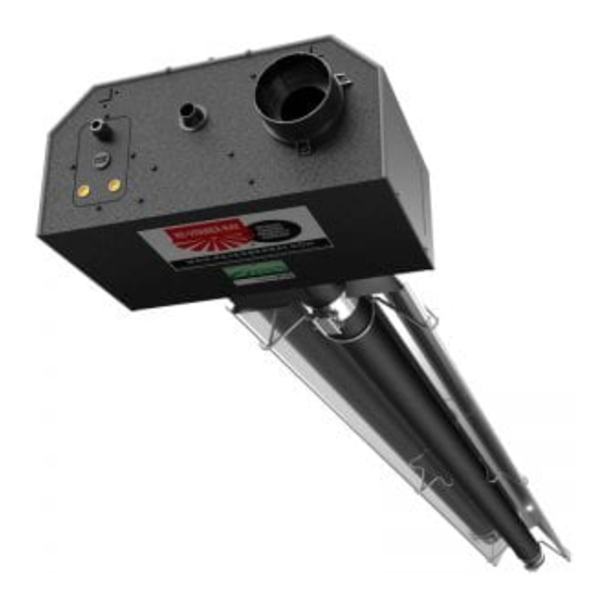
MP Series
Insert Manual
For complete installation instructions, see the Tube Heater General Manual
that accompanies this Series Insert Manual.
The MP Series Infrared Tube Heater is a positive pressure, modulating radiant heater system. This insert
manual is a supplement to the Tube Heater General Manual and provides specific information related to
the MP Series model. All persons involved with the installation, operation and maintenance of the heater
system must read and understand the information in this insert manual and the accompanying Tube
Heater General Manual.
Improper installation, adjustment, alteration, service or maintenance can cause
property damage, injury or death. Read the installation, operation and maintenance
instructions thoroughly before installing or servicing this equipment.
This heater must be installed and serviced by trained gas installation and service
personnel only. Failure to comply could result in personal injury, asphyxiation, death,
fire or property damage.
In locations used for the storage of combustible materials, signs must be posted to
specify the maximum permissible stacking height to maintain the required clearances
from the heater to the combustibles. Signs must either be posted adjacent to the
heater thermostats or in the absence of such thermostats, in a conspicuous location.
Not for residential use! Do not use this heater in the home, sleeping quarters,
attached garages, etc. Installation of a commercial tube heater system in
residential indoor spaces may result in property damage, serious injury,
asphyxiation or death.
For Your Safety
If you smell gas:
• Do not try to light any appliance.
• Do not touch any electrical switch.
• Do not use any phone in your building. • If you cannot reach your gas supplier, call the fire department.
WARNING
!
• Immediately call your gas supplier from a neighbor's phone.
• Follow the gas supplier's instructions.
Keep these instructions for future reference.
LIOMP-Rev. 02012
Print: 1M-2/12(DRP)
Advertisement
Table of Contents

Related Manuals for Re-Verber-Ray MP-25-80N


Summary of Contents for Re-Verber-Ray MP-25-80N
- Page 1 MP Series Insert Manual For complete installation instructions, see the Tube Heater General Manual that accompanies this Series Insert Manual. The MP Series Infrared Tube Heater is a positive pressure, modulating radiant heater system. This insert manual is a supplement to the Tube Heater General Manual and provides specific information related to the MP Series model.
- Page 2 Series Contents .0 Safety..............3 Safety Labels and Their Locations .
-
Page 3: Safety
- 120V HEATER INPUT - F/N: LLV3EP18 F/N: LLTB018 (Natural Gas) F/N: LLTB019 (LP Gas) F/N: LLV3EP6 (Operational Indicator Lights) Top Panel F/N: LLTCL001L2/LLTCL002C2/LLTCL002R Safety & Clearance Labels F/N: LLLOGO19 MP Series Logo Label Bottom Panel F/N: LLLOGO1 Re-Verber-Ray Logo Label... -
Page 4: Clearances To Combustibles
2. Remove cover by lifting top cover upward and outward. CAUTION: HOT SURFACE. KEEP COVER IN PLACE. REMOVE FOR SERVICE ONLY. RE-VERBER-RAY INFRA-RED RADIANT TUBE HEATER ® FOR OUTDOOR USE AND INDOOR (Non-Residential) INSTALLATION ONLY. Class IIIA Permanent Label Rating MODEL NO. - Page 5 Series Safety • Clearance to Combustibles When installing the tube heater system, clearances to combustibles for the model tube heater and configuration must be maintained. Refer to Chart 1.1 below to determine the required distances for your model. Chart 1.1 • Clearance to Combustibles in Inches (See Figure 1.1 for Mounting Angles) Sides Mounting...
-
Page 6: Installation
Installation • Gas Requirements • Electrical Requirements Series Installation WARNING Improper installation, adjustment, alteration, service or maintenance can cause property damage, serious injury or death. Read and understand the installation, operating and maintenance instructions thoroughly before installing or servicing this equipment. Only trained, qualified gas installation and service personnel may install or service this equipment. -
Page 7: Thermostat And Other Controls
Series Installation • Thermostat and Other Controls WARNING Electric Shock Field wiring to the tube heater must be connected and grounded in accordance with national, state, provincial, local codes and to the guidelines in the Tube Heater General Manual and Series Insert Manual. -
Page 8: Zoning Heaters And Configuring 'Master/Slave' Heaters
Installation • Thermostat and Other Controls • Zoning Heaters • Control Devices Series Zoning Heaters and Configuring ‘Master/Slave’ Heaters The MP Series is designed to allow for several heaters within the same zone to simultaneously modulate in synchronization when connected to a single control device. This configuration requires one ‘Master’ heater that is connected directly to the heat control device, and the remaining ‘Slave’... -
Page 9: Field Wiring
Series Installation • Thermostat and Other Controls • Field Wring Field Wiring Field Supplied Control Wire: 18AWG plenum rated thermostat wire that is shielded w/ drain wire is recommended for optimal performance. Installing the Control Wire: Each heater includes a thermostat wire grommet to allow for thermostat wire to be brought into the burner box. - Page 10 Installation • Thermostat and Other Controls • Field Wiring Series Field Wiring Diagram “A” Figure 2.2 • A. Premium User Interface FOR USE WITH TP-3228 MASTER DIP SETTINGS SLAVE DIP SETTINGS SLAVE HEATER PREMIUM USER INTERFACE MASTER HEATER LEGEND NOTE: SHIELD GROUND MUST BE TIED TO GROUND, AS SHOWN...
- Page 11 Series Installation • Thermostat and Other Controls • Field Wiring Field Wiring Diagram “B” Figure 2.3 • B. 10k OHM Potentiometer FOR USE WITH TP-3225 MASTER DIP SETTINGS SLAVE DIP SETTINGS MASTER HEATER SLAVE HEATER LEGEND...
- Page 12 Installation • Field Wiring Diagrams Series Field Wiring Diagram “C” Figure 2.4 • C. Single-stage thermostat FOR USE WITH TP-3224 MASTER DIP SETTINGS SINGLE-STAGE THERMOSTAT SLAVE DIP SETTINGS ROOM THERMISTOR MASTER HEATER SLAVE HEATER LEGEND...
-
Page 13: Internal Wiring
Series Installation • Internal Wiring Field Wiring Before field wiring this appliance - Check existing wiring; replace if necessary. Note: If any of the original wire supplied with the appliance must be replaced, it must be replaced with wiring material having a temperature rating of at least 105°C and a voltage rating of 660V. Figure 2.5 •... -
Page 14: Configuring The Heater
Installation • Configuring the Heater Series Configuring the Heater The MP Series heater utilizes DIP switches on the modulating controller to configure various options available. The DIP switches are located under the modulating circuit board cover (See Figure 2.6), and are labeled “Options”... -
Page 15: Address' Dip Switches
Series Installation • Configuring the Heater Standard Configuration: From the factory, the heater is configured as follows: ’Master’ Heater: ON Outdoor Air Probe: OFF Premium User Interface: ON Potentiometer: OFF Thermostat: OFF Economy Mode: OFF Standard Mode: ON Comfort Mode: OFF MASTER DIP SETTINGS Figure 2.7 •... -
Page 16: Product Specifications
Installation • Product Specifications Series Product Specifications Chart 2.1 • Specifications MP-25-80 N or LP 85,000 52,000 - 80,000 26’-9” 13’-1” 10 ft. 12’ to 20’ Alum Alum MP-30-80 N or LP 85,000 52,000 - 80,000 31’-5” **17’-9” 10 ft. 12’... -
Page 17: Tube Installation Sequence
Series Installation • Tube Installation Sequence Tube Installation Sequence Figure 2.9 • Tube Installation Sequence Important! The combustion chamber & radiant tube sections must be installed in the following order. 25 Foot 30 Foot 40 Foot Stainless steel clamp location on 200,000 BTU/h models (P/N: TP-220). 50 Foot Stainless steel clamp location on 200,000 BTU/h models (P/N: TP-220). -
Page 18: Operation
Operation • Sequence of Operation Series Operation WARNING This heater must be installed and serviced by trained gas installation and service personnel only. Do not bypass any safety features or the heater’s built in safety mechanisms will be compromised. Note: Reference the Tube Heater General Manual for installation requirements. Sequence of Operation There are two (2) main controllers for the MP Series heater. -
Page 19: Performance Curves
Series Operation • Sequence of Operation • Performance Curves Running Circuit: After ignition, the flame rod continuously monitors the flame presence. If sense of flame is lost for a time of 1.0 seconds or greater, the TP-351A closes the gas valve circuit and a new trial for ignition sequence is initiated. -
Page 20: Diagnostics
Operation • Sequence of Operation • Diagnostics Series Shut-down: When the thermostat is satisfied, the TP-3250 will de-energize the 120VAC power to the common side of the pressure switch, de-energizing the thermostat circuit on the TP-351A. The blower motor will continue to cycle for a period of 2 minutes for a post-purge cycle. - Page 21 Series Operation • Diagnostics Figure 3.2 • Circuit Board LEDs LED1 LED2 LED3 LED4 LED1 LED1 LED5 LED2 LED3 LED4 LED6 LED5 LED6 LED2 LED3 LED4 LED5 LED6 Chart 3.1 • Operation LED Color Description Operation Green Relay ON On if relay ON to ignition module. Chart 3.2 •...
-
Page 22: Troubleshooting Guide
Troubleshooting Guide Series Troubleshooting Guide Turn on control Replace or Find source of device for heat. repair damaged electrical problem components. and repair. Is the control Does the heater Does the fan device or have 120VAC at blower turn on? thermostat wire the power entry damaged? - Page 23 Series Troubleshooting Guide Bypassing any switch is intended for testing purposes only. Do not leave switch bypassed NOTICE during normal operation or the heater’s built-in safety mechanisms will be compromised. Process Start Corrective Question Question Action Is the fan obstructed Is there 90-120VAC or locked in place by a Remove obstruction.
- Page 24 Troubleshooting Guide Series Continued from Page 22 Continued from Page 22 Turn on the gas supply line. Is the gas supply valve Check the voltage at Does the burner to the heater in the “on” the relay coil during the ignite? position? ignition sequence.
- Page 25 Series Troubleshooting Guide Check wiring and repair. Replace valve wire. Is there 120VAC on the primary side of the transformer across the BLACK and WHITE wires? Replace transformer. Disconnect the main wire to the valve and Is there 24VAC on the check for resistance Is the relay switching secondary side of the...
-
Page 26: Parts
Parts • Heater Components and Parts List Series Parts Figure 5.1 • Burner Assembly Components 3097A 3098 3060 3011 3002A 3094A 3096A 3044 3012 3240, 3241 3008 3094A 3001 3005A 3380 351A 3235 3223 3099A 352A 3260 264B,E, 1264A 3225 3261 3093 3254... - Page 27 Series Parts • Heater Components and Parts List Figure 5.2 • Tube & Reflector Components 20C/D*, 112 26A/D*, 111 26A/B/E* 21B, 220 Part # Description Part # Description TP-331 Green Self-tap Ground Screw (Qty. 2) TP-3033D Power Entry Plate TP-332 1/4”...
-
Page 28: Mp Series Kit Contents Check List
Series Kit Contents Check List MP Series Kit Contents Check List MP Series Kit Contents - Reference the length column for your model. TP-3228 TP-19B 4” Hanger TP-82 4” Reflector TP-33B 1/2” Shut- TP-106 TP-3220 Terminal with Tension Spring Center Support (RCS) Off Valve (Ball Reflector Thermostat...
Need help?
Do you have a question about the MP-25-80N and is the answer not in the manual?
Questions and answers