Table of Contents
Advertisement
Quick Links
MP3 Series
Insert Manual
For complete installation instructions, see the Tube Heater General Manual
that accompanies this Series Insert Manual.
The MP3 Series Infrared Tube Heater is a positive pressure, modulating radiant heater system. This insert
manual is a supplement to the Tube Heater General Manual and provides specific information related to the
MP3 Series models. All persons involved with the installation, operation, and maintenance of the heater
system must read and understand the information in this insert manual and the accompanying Tube Heater
General Manual.
Improper installation, adjustment, alteration, service, or maintenance can cause
property damage, injury, or death. Read the installation, operation, and maintenance
instructions thoroughly before installing or servicing this equipment.
This heater must be installed and serviced by trained gas installation and service
personnel only. Failure to comply could result in personal injury, asphyxiation, death,
fire, or property damage.
In locations used for the storage of combustible materials, signs must be posted to
specify the maximum permissible stacking height to maintain the required clearances
from the heater to the combustibles. Signs must either be posted adjacent to the heater
thermostats or, in the absence of such thermostats, in a conspicuous location.
Not for residential use! Do not use this heater in the home, sleeping quarters,
attached garages, etc. Installation of a commercial tube heater system in residential
indoor spaces may result in property damage, serious injury, asphyxiation, or death.
For Your Safety
If you smell gas:
• Do not try to light any appliance.
• Do not touch any electrical switch.
• Do not use any phone in your building.
INSTALLER: Present this manual to the end user.
Keep these instructions in a clean and dry place for future reference.
Model#: ___________________Serial #: _________________________
WARNING
!
• Immediately call your gas supplier from a neighbor's phone.
• Follow the gas supplier's instructions.
• If you cannot reach your gas supplier, call the fire department.
(located on rating label)
LIOMP3-Rev. 33123
Print: XM-01/24 (CDS)
Advertisement
Table of Contents

Related Manuals for Re-Verber-Ray MP3 Series


Summary of Contents for Re-Verber-Ray MP3 Series
- Page 1 For complete installation instructions, see the Tube Heater General Manual that accompanies this Series Insert Manual. The MP3 Series Infrared Tube Heater is a positive pressure, modulating radiant heater system. This insert manual is a supplement to the Tube Heater General Manual and provides specific information related to the MP3 Series models.
-
Page 2: Table Of Contents
MP3 Series Kit Contents Check List ........ -
Page 3: Safety
Series Safety • Safety Labels and Their Locations Safety WARNING Improper installation, adjustment, alteration, service, or maintenance can cause property damage, serious injury, or death. Read and understand the installation, operating, and maintenance instructions thoroughly before installing or servicing this equipment. Only trained, qualified gas installation and service personnel may install or service this equipment. -
Page 4: Clearances To Combustibles
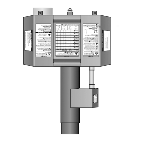
2. Remove cover by lifting top cover upward and outward. CAUTION: HOT SURFACE. KEEP COVER IN PLACE. REMOVE FOR SERVICE ONLY. RE-VERBER-RAY INFRA-RED RADIANT TUBE HEATER LOW-INTENSITY INFRARED HEATER ® FOR OUTDOOR USE AND INDOOR (Non-Residential) INSTALLATION ONLY. RADIATEUR À INFRAROUGE À FAIBLE INTENSITÉ... - Page 5 Series Safety • Clearances to Combustibles When installing the tube heater system, clearances to combustibles for the model tube heater and configuration must be maintained. Refer to Chart 1.1 below to determine the required distances for your model. Chart 1.1 •...
-
Page 6: Installation
Series Installation • Gas Requirements • Electrical Requirements Installation WARNING Improper installation, adjustment, alteration, service, or maintenance can cause property damage, serious injury, or death. Read and understand the installation, operating, and maintenance instructions thoroughly before installing or servicing this equipment. Only trained, qualified gas installation and service personnel may install or service this equipment. -
Page 7: Internal Wiring
F.C. TEST PINS IGNITER FLAME SENSOR MODULATING THERMOSTAT CONTROLLER 1 2 3 4 5 6 10 11 12 LLWT382a MP3 SERIES BLOWER ALM+ ALM- LLWT382a 13 14 15 16 17 18 19 20 21 22 23 24 MP3 SERIES DICATOR... -
Page 8: Field Wiring
Series Installation • Field Wiring • Controlling Multiple Heaters with a Single Control Device Field Wiring Figure 2.2 • Single Heater, Single Thermostat Connection THERMOSTAT CONSTANT 120V 7 8 9 10 1 2 3 4 R BL BR GY REMOTE SENSOR IF USED CONFIGURE 13 14 15 16 17 18... - Page 9 Series Installation • Field Wiring • Controlling Multiple Heaters with a Single Control Device 40 VA TRANSFORMER 120V...
-
Page 10: Product Specifications
Series Installation • Product Specifications Product Specifications Chart 2.1 • Specifications MP3-20-75 N or P 65,000 - 75,000 21’-9” 13’-1” 10 ft. 12’ to 20’ Alum Alum 5 1/2 MP3-20-80 65,000 - 80,000 21’-9” 13’-1” 10 ft. 12’ to 20’ Alum Alum 5 1/2 MP3-25-80 N or P... -
Page 11: Tube Installation Sequence
Series Installation • Tube Installation Sequence Tube Installation Sequence Chart 2.2 • Tube Installation Sequence, Baffle Location, and Secured Joints for Reflectors NOTE: When securing joints on reflectors which are rotated on an angle from horizontal, secure joint only on top side of reflector to allow for sufficient heater expansion and contraction. -
Page 12: Operation
Note: Reference the Tube Heater General Manual for installation requirements. Sequence of Operation There are three (3) main control devices for the MP3 Series heater. • The TH-PC-M (or other compatible) thermostat sends a 24 VAC signal to the heater to enable the unit to call for heat, and a 0–10 VDC signal to modulate the heater based on demand. -
Page 13: Diagnostics
Series Operation • Sequence of Operation • Diagnostics If the burner fails to light or flame is not detected within eight (8) seconds, the gas valve circuit is de-energized and the control performs an inter-purge delay before attempting another ignition sequence. The control will attempt two (2) additional ignition trials before entering the soft lockout sequence, which turns off the gas valve immediately, though the blower will continue to operate. -
Page 14: Troubleshooting Guide
Troubleshooting Guide Series Troubleshooting Guide Turn on control device for heat. Replace or repair Find source of electrical damaged components. problem and repair. Does the heater Is the control device Does the fan have 120 VAC at or thermostat wire blower turn on? the power entry damaged? - Page 15 Series Troubleshooting Guide Bypassing any switch is intended for testing purposes only. Do not leave switch bypassed during NOTICE normal operation or the heater’s built-in safety mechanisms will be compromised. Modulating controller Fan is faulty. is faulty. Start Process Corrective Question Question Action...
- Page 16 Troubleshooting Guide Series Continued from Page 14 Does the heater’s gas Does the burner Contact local representative or type match the gas ignite? factory. supplied? Is the gas supply valve to the heater in Open gas supply valve. the open position? Are the pressure The fan is faulty or there Does the burner...
- Page 17 Series Troubleshooting Guide Continued from Page 15 Replace ignition module. Temporarily disconnect igniter from harness and check the resistance. Is Ω it within the range of 50-400 Replace igniter. The fan is faulty or there Are the pressure Purge gas lines. is a restriction in the switch readings intake or exhaust.
-
Page 18: Parts
Series Parts • Heater Components and Parts List Parts Figure 5.1 • Burner Assembly Components 3097A 3060 3011 3098 3002A 3096A 3094A 3012 3340, 3341 3094A 3001 351A 3005A 3380 352A 3099B 264B, D, G, 664J 260H 3260A 3254A 3072, 3073, 201B 3250A 3025 3261A... - Page 19 Series Parts • Heater Components and Parts List Figure 5.2 • Tube and Reflector Components 20C/D*, 112 26A/D*, 111 26A/B/E* 21B, 220 65H, I Chart 5.1 • Parts List (cont.) Part # Description Part # Description TP-321 Ignition Plate Gasket TP-3014 Pastic Air Orifice with Screen TP-328...
-
Page 20: Mp3 Series Kit Contents Check List
Series Parts • Kit Contents Kit Contents MP3 Series Kit Contents - Reference the length column for your model. TP-19B 4” Hanger TP-82 4” Reflector TP-105 Reflector TP-106 TP-3220 with Tension Spring Center Support (RCS) End Cap Reflector Thermostat Wire...
Need help?
Do you have a question about the MP3 Series and is the answer not in the manual?
Questions and answers