Table of Contents
Advertisement
Advertisement
Table of Contents

Related Manuals for Netafim nmc-pro


Summary of Contents for Netafim nmc-pro
- Page 2 ALTHOUGH NETAFIM TAKES THE GREATEST POSSIBLE CARE IN DESIGNING AND PRODUCING BOTH ITS PRODUCTS AND THE ASSOCIATED DOCUMENTATION, THEY MAY STILL INCLUDE FAULTS. NETAFIM WILL NOT ACCEPT RESPONSIBILITY FOR DAMAGE RESULTING FROM THE USE OF NETAFIM'S PRODUCTS OR THE USE OF THIS MANUAL.
- Page 3 Drainage EC Level Influence on Target EC ....................33 2.8.6 VPD Influence on Target EC ........................35 2.8.7 Temperature Influence on Target EC ......................36 Agitator ................................37 2.10Selector................................. 38 2.11Filter Flushing ............................... 38 2.12Cooling.................................. 41 2.13Misting .................................. 42 NMC-PRO User Manual Page 3...
- Page 4 Irrigation Accumulation ............................57 Aux Meter Accumulation ............................ 57 Accumulation Reset ............................57 Filters .................................. 58 5.10 Cooling ................................58 5.11 Sensor Log ................................. 59 5.12 Event Log ................................59 5.13 System Log ................................ 59 NMC-PRO User Manual Page 4...
-
Page 5: General Information
• 2: Irrigation Process • 3: Irrigation Program Status • 4: Water, EC/pH, Dosing • 5: Filter Flushing Status • 6: Temperature & Humidity measurement • 7: Weather Station measurement • 8: System Pressure • 9: Drain Status NMC-PRO User Manual Page 5... -
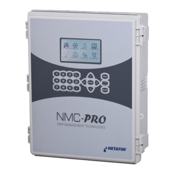
Page 6: Main Menu Icons
1.Program 2.Manual 3.Alarm 4.History Manually test field devices 5.Test 6.Setup 7.Config 8.Install (valves, pumps…), sensor values (EC, pH, temp, hum…) professional technical use only System set-up, time/date, professional sensors technical use calibration, unit only measurements NMC-PRO User Manual Page 6... -
Page 7: Introduction To Irrigation Programs
• Read Only (restricted): All the parameters and menus are visible, but cannot be modified • User (partially restricted): Menus 1-6 are fully accessible and can be modified. Menus 7 and 8 can be viewed but not modified • Technician (unrestricted): All menus are fully accessible (no restrictions) NMC-PRO User Manual Page 7... - Page 8 Upper Port – BaudRate 9600 • To perform a cold start or firmware upgrade, the controller must be in the “Technician” mode. • If there is a power failure, the controller powers up with the last used mode. NMC-PRO User Manual Page 8...
-
Page 9: Program Menu
1. Go to Program > Water Run Time. 2. Select QTY or TIME. 3. Enter the water quantity/total run time. 4. Enter the Before and/or After quantity/time (optional). 5. Repeat as required for each program. NMC-PRO User Manual Page 9... - Page 10 Note: Whatever figure you enter in Before/After is deducted from the total run time/quantity. For example if the run time is 15 minutes, a Before time of two minutes and After time of one minute, then the net dosing time is 12 minutes. NMC-PRO User Manual Page 10...
-
Page 11: Dosing Program
• Liters per cube of water • Gallons per 1000 gallons of water DOSING PROGRAM Program: INJECTION PER DOSING CHANNEL ACID 5:00 6:00 0.00 P. QTY EC Dosing Method P.TIME P. TIME PH Dosing Method P.QTY TIME QTY. NMC-PRO User Manual Page 11... -
Page 12: Proportional Time
PH Dosing Method P.QTY TIME QTY. DOSING PROGRAM Program: INJECTION PER DOSING CHANNEL ACID 00:15 00:10 00:05 EC Dosing Method TIME PH Dosing Method TIME Example: In Channel 3, P1 = 5 minutes. (one pulse) NMC-PRO User Manual Page 12... -
Page 13: Quantity
INJECTION PER DOSING CHANNEL ACID 4.00 5.00 2.00 EC Dosing Method QTY. PH Dosing Method QTY. When installing the NMC Pro Controller, the installation technician selects the required option. The user defines the quantity in the above screen. NMC-PRO User Manual Page 13... - Page 14 INJECTION PER DOSING CHANNEL PASSIV PASSIV ACID 4.00 5.00 2.00 Target PH 5.50 Passive Method QTY. PH Dosing Method P.QTY. Ch. 1 Spread Qty. = 4 liters Ch. 2 Spread Qty. = 5 liters NMC-PRO User Manual Page 14...
- Page 15 **Channel 3 (Acid channel): pH is controlled at 5.50. To keep pH levels on target, the Pulse width (meaning the quantity in each pulse) fluctuates according to controller calculations. 3 liter 1m³ pH Target = 5.5 NMC-PRO User Manual Page 15...
-
Page 16: Ec Pre-Control
PH Dosing Method P.QTY DOSING PROGRAM Program: EC Pre-Control: INJECTION PER DOSING CHANNEL ACID 2.00 5.00 3.00 Target EC 1.50 Target PH 5.50 Target EC Pre-Control 0.80 EC Dosing Method P.QTY PH Dosing Method P.QTY NMC-PRO User Manual Page 16... -
Page 17: Irrigation Program
Adjusting the Water Quantity Based on Weather Conditions, page 20 Irrigation Based on External Conditions, page 22 Irrigation Based on Radiation Sum, page 27Irrigation Based on VPD Sum, page 28 Introduction to the Influence Program, page 29 NMC-PRO User Manual Page 17... -
Page 18: Setting Valve Sequence
In this example, two valves operate simultaneously (valves operating together is a called a group). All other specifications are the same as those found in Example 1. Note: Valves in the same group must have the same run time. NMC-PRO User Manual Page 18... - Page 19 TIME : 16:12:32 IRRIGATION PROGRAM Program: 4 Priority: Const. Start Time 08:00 10:30 12:30 Clock Start Min. Time 01:00 00:30 01:00 Valve # 001 + 002 003 Run Time # Dosing Prog Day: 01/03 Dose/Water NMC-PRO User Manual Page 19...
-
Page 20: Adjusting The Water Quantity Based On Weather Conditions
• Const: Program adjustment continues until changed. DATE : 19-Apr-07 TIME : 16:12:32 IRRIGATION PROGRAM Program: Priority: Daily Start Time 08:00 10:30 Clock Start Min. Time 01:00 00:30 Valve # 001+002 003 Run Time # Dosing Prog Day: 01/01 Dose/Water NMC-PRO User Manual Page 20... -
Page 21: Configuring The Irrigation Calendar
Run Time # Dosing Prog Day: 01/01 Dose/Water 2.3.3 Configuring the Irrigation Calendar NMC-Pro enables scheduling irrigation programs by: • Daily calendar • Irrigation by dosing or water When setting up a schedule, configure the following: • Day: X/Y X represents the first day that the cycle begins. For example, if you want to define the first day of the cycle as day 4, define X as 4. -
Page 22: Irrigation Based On External Conditions
NMC Pro supports up to 15 extension programs defining which trigger initiates irrigation. In each program, the start and stop trigger must be the same type (meaning both must be dry contact or analog sensor). NMC-PRO User Manual Page 22... -
Page 23: Setting The Dry Contacts
Start Trigger Stop Dry Cont. Type Dry Cont. Dry Con 1 Dry Con 2 <NONE> Shot <NONE> <NONE> <NONE> <NONE> Shot <NONE> <NONE> <NONE> <NONE> Shot <NONE> <NONE> <NONE> <NONE> Shot <NONE> NMC-PRO User Manual Page 23... -
Page 24: Configuring The Analog Sensors
Sensor Type Min Value Max Value -> -> -> <NONE> -> -> -> ECh20 -> -> -> Netasense -> -> -> Gen. Sensor Temperature 2. In Test > Analog Sensor, view the actual sensor values. NMC-PRO User Manual Page 24... - Page 25 One Shot <NONE> Only If On Ana. Sen 3 <NONE> Ana. Sen 4 <NONE> One Shot <NONE> Ana. Sen 5 <NONE> One Shot <NONE> Ana. Sen 6 <NONE> One Shot <NONE> One Shot <NONE> <NONE> NMC-PRO User Manual Page 25...
- Page 26 The analog sensor function value is equal to the start/stop value. There is a ± 1% allowable deviation. >, >= The analog sensor function value is greater than/greater than or equal to the start/stop value. NMC-PRO User Manual Page 26...
-
Page 27: Irrigation Based On Radiation Sum
08:00 10:00- 16:00 Clock Start Rad Sum Li. ---- Min. Time --:-- 00:30 00:20 --:-- Max. Time --:30 01:00 01:00 --:-- Valve # Run Time # Dosing Prog For Next Screen Press The DOWN Arrow NMC-PRO User Manual Page 27... -
Page 28: Irrigation Based On Vpd Sum
• Clock Start: Number of cycles. 0 (zero) means that this program is disabled. 1 (one) means that this program runs one time after time-based irrigation is completed. 2 (two) means that the program runs twice, and so on. NMC-PRO User Manual... -
Page 29: Introduction To The Influence Program
1. Go to Install > Device Layout. 2. Define relays as dosing channels, as required. 3. Go to Program > Irrigation. 4. Using the arrow keys, scroll down to Screen 2. The following screen appears. NMC-PRO User Manual Page 29... -
Page 30: Radiation Influence On Target Ec
6. Define the EC change in percentages. 7. Set ACTIVE/SOURCE to Yes. 8. Press Menu and confirm changes. 9. In Program > Dosing Program, set: a. the Target EC b. EC Dosing Method to Qty NMC-PRO User Manual Page 30... -
Page 31: Drainage Influence On Target Radiation Sum
Note: The drainage must be defined correctly! You can check the drainage meter status using Hot key 9. 3. In Configuration > Valve Configuration define which valve number corresponds to which drainage meter. 4. In Configuration > Drainage Configuration, define the drainage meter’s Ratio Liter/Pulse. NMC-PRO User Manual Page 31... -
Page 32: Drain Influence On Minimum Time
2. In Configuration > Valve Configuration define which valve number corresponds to which drainage meter. 3. In Configuration > Drainage Configuration, define the drainage meter’s Ratio Liter/Pulse. 4. In Program > Irrigation, select Drain/MinT. a. Define the Drainage percentage set points. NMC-PRO User Manual Page 32... -
Page 33: Drainage Ec Level Influence On Target Ec
If you have installed an EC sensor in the drainage, you can adjust the Target EC level based on the drainage EC level. This can be used, for example, to lower the EC input if EC levels in the drainage are above specifications. To set the EC Drainage Influence on the EC: NMC-PRO User Manual Page 33... - Page 34 Example: A user wants to maintain an EC level of 1.5. To this end, he measures the drainage EC. When the drainage EC falls below 1.5, he increases the EC input. As it rises above 1.5 ms/cm, he decreases the input. NMC-PRO User Manual...
-
Page 35: Vpd Influence On Target Ec
Define the VPD sum points. b. Define the EC percentage set points. 6. Set ACTIVE/SOURCE to Yes. 7. In Program > Dosing Program: a. Set the Target EC. b. Set EC Dosing Method to Qty. NMC-PRO User Manual Page 35... -
Page 36: Temperature Influence On Target Ec
Target EC. b. set EC Dosing Method to Qty. Example: A grower’s flower crop requires higher EC levels when the temperature goes above room temperature 22° C). Using this screen, he can adjust the levels accordingly. NMC-PRO User Manual Page 36... -
Page 37: Agitator
• Select Serial if not enough mm:ss mm:ss Dosing Active 01:00 05:00 power to operate more than Dosing Not Active 05:00 60:00 one agitator at a time Operation Mode Serial NMC-PRO User Manual Page 37... -
Page 38: Selector
Delay Between Filters Set delay between the flushing of each filter (to build up pressure). Set flush by pressure sensor. Pressure at filter inlet/outlet, if there is a significant Delta Pressure difference, a filter may be blocked. NMC-PRO User Manual Page 38... - Page 39 Set to give signal after XX flushes. If Delta Pressure still indicates a blockage, an Delta Pressure Reiteration alarm will be raised. Open main filter valve before flush to balance pressure for a reliable flushing Dwell Time Main process. NMC-PRO User Manual Page 39...
- Page 40 PROGRAM MENU NMC-PRO User Manual Page 40...
-
Page 41: Cooling
Off time can be controlled according to temp. Program: 1 Status: Cooling High temp.= less off time Below RH Low temp.= more off time 00:00:10 00:00:10 00:00:10 00:00:10 Cool# Temp. Sens.: 1 2-- Hum. Sens.: 1 2 NMC-PRO User Manual Page 41... -
Page 42: Misting
From Time 08:00 1. Program To Time 16:00 Water Temperature 20.0 Difference Define Start/End time Temp. Sensor #1 Define Water Temp. ± Temp. Sensor #2 Difference (dead band) to stop Define sensors NMC-PRO User Manual Page 42... -
Page 43: Manual Menu
PAUSE IRRIGATION 15:38:16 DOSING VALVE: 1 25-Apr-07 FILTER S tart/Stop Program 2 5 B 2. Start/Stop Select Program Program 2. Manual To resume, reverse steps above and select NO START/STOP PROGRAM Program: NMC-PRO User Manual Page 43... -
Page 44: Start/Stop Valve
Run Time # Dosing Program DOSING PROGRAM Program: INJECTION PER DOSING CHANNEL Dosing Program (1) ACID 5.00 5.00 5.00 5.00 3.00 Target EC 1.60 Target PH 5.50 EC Dosing Method P.QTY PH Dosing Method P.QTY NMC-PRO User Manual Page 44... -
Page 45: Manual Filter Flush
Water Leak Period (hh:mm) 00:30 Identify Leak-Subtr. Meter? Dosing Channel Leak Delay(s) Dosing Channel Leak (Pulse) Dosing Flow Difference (%) Missing Pulses For No Flow Stop System Cons.Flow Alarms # of Irrig. Without Drainage NMC-PRO User Manual Page 45... -
Page 46: Alarm Menu
ACTIVE ALARMS Message Date Time None "Complete Irrig. On Reset?" Select Yes or No ALARM RESET Reset Now? Period Of Automatic Reset 24 h Complete Irrig. On Reset? ACTIVE ALARMS Message Date Time NMC-PRO User Manual Page 46... -
Page 47: Alarm History
Delay between switching off a dosing channel and generating dosing leak alarm. Delay (s) Dosing Channel Leak Number of pulses (by dosing meter) during the delay above to generate an alarm. (Pulse) Example: 10 pulses in 3 seconds generate an alarm. NMC-PRO User Manual Page 47... - Page 48 (60 – 350) (For technician use only) Short O. Level EXT3 Define the A/D threshold value to be considered as a short circuit for Extension box no. 3 (60 – 350) (For technician use only) NMC-PRO User Manual Page 48...
-
Page 49: Alarm Setting
EC-Pre. Low STOP STOP 01:00 Alarm output activation: YES/NO (siren, light). E. Tank Fresh STOP STOP 01:00 E. Tank Drain STOP STOP 01:00 EC Sen. Dif. STOP STOP 01:00 pH Sen Dif. STOP STOP 01:00 NMC-PRO User Manual Page 49... -
Page 50: Radio System Alarm Definition
The S/N column is the unit number. When an Open Circuit or Short Circuit alarm is detected, the system also displays the card number and the input/output number that is problematic. For example: RTU – 0555.3.1 UNIT # CARD # INPUT/OUTPUT# Exiting and re-entering refreshes the alarm status screen. NMC-PRO User Manual Page 50... -
Page 51: Sms Subscription
• PRIORITY: Send an SMS for this alarm as soon as it appears regardless of “Send Period” time constraints Note: Refer to the SETUP section (Menus 6.11-6.13) in the Installation manual for more information on the SMS feature. NMC-PRO User Manual Page 51... -
Page 52: History Menu
H ISTORY MENU The History Menu consists of read-only screens detailing the system's history data (measurements, settings, processes, events, graphs and so forth). The History Menu provides extensive information regarding measurements and processes performed by the NMC-Pro. 11. Sensor Log SENSORS LOG Time Avg. -
Page 53: Irrigation Log
Average EC value recorded during irrigation. EC High Highest EC value recorded during irrigation. pH Low Lowest pH value recorded during irrigation. pH Avg. Average pH value recorded during irrigation. pH High Highest pH value recorded during irrigation. NMC-PRO User Manual Page 53... - Page 54 Percentage of drain for relevant irrigation cycle. Drain Drain quantity related to relevant irrigation. Rad Sum Accumulated radiation sum level when irrigation started. Interval Time (in minutes) since last irrigation cycle. Refers to the last irrigation of a specific valve. NMC-PRO User Manual Page 54...
-
Page 55: Uncompleted Irrigation
‘+’ sign is added next to it to indicate that more valves are Vl. No. associated. The NMC-Pro will attempt to complete the irrigations from the current day (until end day time) upon manual or automatic alarm reset. The valve column of irrigations that are to be completed will be highlighted. -
Page 56: Uncompleted Programs
(liter or gallon). To 30.87 30.82 30.83 19.06 19.97 18.12 toggle the view between 25.25 26.01 24.49 quantities and time, press the 0.00 0.00 0.00 ‘+/-‘ key 0.00 0.00 0.00 Press +/- to Toggle Quantity/Time NMC-PRO User Manual Page 56... -
Page 57: Irrigation Accumulation
<None> reset option accumulation using of a specific arrow valve or all keys valves. Note: When resetting a valve (or all valves), its history is erased from the Daily Irrigation and Irrigation Accumulation tables: NMC-PRO User Manual Page 57... -
Page 58: Filters
From Cycles view the accumulated history since the last End Day. hh:mm hh:mm 13:10 18:14 13:13 18:14 --:-- --:-- ----- --:-- --:-- ----- --:-- --:-- ----- --:-- --:-- ----- --:-- --:-- ----- --:-- --:-- ----- NMC-PRO User Manual Page 58... -
Page 59: Sensor Log
For example: logging of two sensors uses four data fields; two for time and date and one for each sensor. In this case, the table will consist of a maximum of 2,500 lines. 5.12 E vent Log 4 8 B The table provides information of all the processes performed by the NMC-Pro including their time and date. EVENT LOG Event Date Time... - Page 60 NMC-PRO User Manual Page 60...
Need help?
Do you have a question about the nmc-pro and is the answer not in the manual?
Questions and answers