Truma Combi eco Installation Instructions Manual
Combi lp gas furnace with supplementary indirect water heating
Hide thumbs
Also See for Combi eco:
- Operating instructions manual (20 pages) ,
- Operating instructions manual (72 pages)
Table of Contents
Advertisement
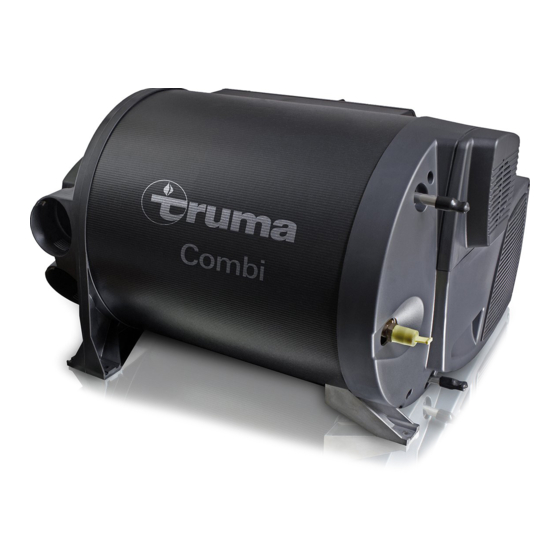
Truma Combi®
LP Gas Furnace with Supplementary Indirect Water Heating
FOR INSTALLER ONLY
To the consumer
Installing this Truma furnace can be hazardous
due to LP gas and electrical components.
These installation instructions are only for use
by trained and qualified technicians.
To the installer
The operating instructions for this Truma
furnace are part of these installation
instructions. The operating instructions are
included with the furnace as a separate
document.
*
Installation instructions
* Patent Pending
Conforms to ANSI Std. Z21.47
Certified to CSA Std. 2.3
4010007
Advertisement
Table of Contents

Related Manuals for Truma Combi eco


Summary of Contents for Truma Combi eco
- Page 1 LP Gas Furnace with Supplementary Indirect Water Heating FOR INSTALLER ONLY Installation instructions To the consumer Installing this Truma furnace can be hazardous due to LP gas and electrical components. These installation instructions are only for use by trained and qualified technicians.
- Page 2 Installing end outlets .............. 17 • Combi comfort plus Gas connection ..............17 Connecting the gas line ............17 The Combi eco plus and Combi comfort plus Checking for gas leaks ............18 furnaces also feature electrical heating elements Water installation ..............19 for a supply voltage of 120 V.
-
Page 3: Mounting Arrangement / Accessories
Wall cowl with exhaust venting system Warm air T-piece (tube in tube) Wall outlet vent Truma pressure relief/drain valve Reducer RZ 35 Non-return valve (optional) Blank cover Truma water pressure regulator (optional) Warm air elbow Warm air ducts with insulation sleeve... -
Page 4: Furnace Diagram
Furnace diagram 1 (top) Fig. 2 1 (top) Fig. 3... - Page 5 5 Connection cover 6 Warm air outlets (upper) 7 Warm air outlets (lower) 8 3-pole 120 volt electrical plug (NEMA 5-20P) (only on Combi eco plus and Combi comfort plus models) 9 Plastic frame feet 10 Aluminum frame feet 11 Circulated air fan...
-
Page 6: Safety Symbols And Signal Words
• Installation and service must be performed rise range with a duct system which has an by an authorized Truma-trained installer. external static pressure within the allowable Improper installation, alteration, service or range, as specified in”Warm air distribution”... -
Page 7: Selecting An Installation Space
Wood or PVC floors typically used in RVs can change color due to the temperature of the Combi furnace. Truma does not accept liability for this. Truma recommends removing the PVC in the area of the furnace. -
Page 8: Dimensions And Clearances
– This applies to items such as service hatch- es and cabinet doors. TOP VIEW – Truma recommends a seating dinette, clos- et or under-bed location. • The Combi furnace must be mounted on a flat surface. It may not be mounted on a wall or in an inverted mounted position. -
Page 9: Clearance From Combustible Materials
RV accident and the gas line can become disconnected. • The floor or false floor must bear the load of a secured furnace. Contact the Truma Service Center on 1-855-558-7862 if you are unsure whether the floor can bear the load of the furnace. -
Page 10: Exhaust Venting System
Exhaust venting system Exhaust accessories Excessive exposure to contaminated combus- The exhaust accessories are legally mandated tion air will result in safety and performance- pieces of furnace equipment. You must install related problems. the original exhaust accessories listed here. There must be no exposure to substances listed Combi in”Appendix A”... -
Page 11: Installation Position: Wall Cowl
Installation position: wall cowl The wall cowl’s installation position in the RV must conform to local regulations. If there are no local regulations, then the installation posi- tion must be in compliance with NFPA 1192 Risk of carbon-monoxide poisoning due (National Fire Protection Association), CSA 2.3 to improper installation position of the (Canadian Standards Association) or NFPA 54. -
Page 12: Making The Exhaust Venting System
Making the exhaust venting system Installing the wall cowl An exhaust venting system consists of a com- 1. Drill a hole with a diameter of 3 1/4 in. bustion-air supply tube (Fig. 10 – 2) and an ex- (83 mm); see Fig. 11. haust tube (Fig. - Page 13 7. Use the hose clamp (Fig. 12 – 4) to secure the combustion-air supply tube (Fig. 12 – 2) – If the surface is not smooth (Fig. 13), coat into the connection (Fig. 12 – 6b). it with a plastic sealant (e.g. sealing based – Use at least one ZRS clamp (Fig. 12 – 9) to on butyl) for vehicle bodies.
-
Page 14: Connecting The Exhaust Venting System To The Combi Furnace
Connecting the exhaust venting Circulated air intake system to the Combi furnace The furnace draws in circulated air from inside the vehicle. 1. Slide the hose clamp (Fig. 15 – 4) onto the combustion-air supply tube (Fig. 15 – 2). 2. Slide the hose clamp (Fig. 15 – 4) with the Risk of carbon-monoxide poisoning! claws facing the furnace over the exhaust If exhaust enters the RV, carbon monoxide... -
Page 15: Warm Air Distribution
VD-Combi • Always use AD 65 or AD 35 warm air Blank cover for Combi ducts supplied by Truma. Closable end outlet • Always make sure that the warm air ducts with air throttle are inserted all the way and check for a tight seat. -
Page 16: Installing Warm Air Ducts
4. Slide the 3 in. insulating sleeve (Fig. 19 – 3) 3 Cable tie and cable tie (Fig. 20 – 3) onto the warm air 4 End outlet nut EM duct AD 65 (Fig. 19 – 1). If necessary, use 5 End outlet EN the tool supplied by Truma (Fig. 19 – 2) to do this. -
Page 17: Installing End Outlets
2. If necessary, line hollow spaces near the drill T-pipe until it fits snugly. Teeth on the inside hole with wood. hold the duct in place. For an even more secure fastening, Truma Installing an AD 65 warm air duct metal clips can be used (see Appendix B). Gas connection... -
Page 18: Checking For Gas Leaks
• If local codes allow the use of a flexible 3. Use a torque wrench to tighten the union nut gas appliance connector, always use a new (nominal torque 15 lb-ft (20 Nm)). listed connector. Do not use a connector which has previously serviced another gas appliance. -
Page 19: Water Installation
5 Truma water pressure regulator (optional) 12 Fresh water tank 6 Non-return valve (optional) 13 Water pump 7 Truma pressure relief/drain valve (not included) 14 Water connection to the fresh water tank 8 Cold water connection 15 Winterizing Kit (example, not in scope of Elbow fitting –... -
Page 20: Advice On Water Installation
Advice on water installation • An adaptor must be installed at every junc- tion between a 12 mm push-fit system and • You need practical experience to make con- a 1/2 in. CTS tube; see”Installing a 12 mm / nections using push-fit systems (e.g. John 1/2 in. -
Page 21: Installing A Water Pressure Regulator
We recom- will prevent hot water from flowing back via the mend the Truma water pressure regulator (not cold water faucet. included in scope of supply). • Install the non-return valve in the cold •... -
Page 22: Installing A Pressure Relief/Drain Valve
3. Install the drainage hose (Fig. 31 – 4) in a Supply Systems, ANSI Z21.22 / CSA 4.4. We straight line to the outdoors, where it must recommend installing the Truma pressure relief/ terminate in a splash-proof position. Install a drain valve (65.25 psi (4.5 bar) – not included in splash guard, if necessary. -
Page 23: Final Tasks
Installing the CP plus control panel 6 Clamp or crimp ring (not included in scope of supply) 7 Venting hose, external diameter 7/16 in. (11 mm) Please refer to the installation instructions sup- plied with the CP plus control panel for further Connecting the cold water line information on how to install the control panel. -
Page 24: Electrical Connections
Electrical connections Electrical connections are underneath the fur- nace’s connection cover (Fig. 35 – 39). While The furnace must be electrically grounded in ac- detaching or reattaching the connection cover, cordance with local codes or, in the absence of take care to neither dislodge nor pinch the con- local codes, with the National Electrical Code, nector cables. -
Page 25: Setting Up A 12-Volt Connection
Fig. 37 Setting up a 120 V connection Setting up a 12-volt connection (Combi eco plus and Combi comfort plus models with electrical heating elements only) The Combi furnace features reverse polar- ity protection. Even in case of an improper... -
Page 26: Final Tasks
Final tasks Ignition control test A duplicate type plate with a removable bar There are two possibilities to detect the flame: code is included in the scope of supply. – Measurement with voltmeter or – Optical detection If the original type plate is not readily visible fol- lowing installation of the furnace, the duplicate 1. -
Page 27: Static Pressure Test
Static pressure test The Combi furnace has an automatic fan speed control. Truma recommends that all 4 warm air outlets should be fitted with warm air ducts. 1. For testing, close all warm air outlets but one. The static pressure should be below 0.65 in. -
Page 28: Connection Diagram 12 Volt (Control_Pcb)
Connection diagram 12 volt (Control_PCB) Fig. 40... -
Page 29: Connection Diagram 120 Volt Ac (120 Vac_E_Pcb)
Connection diagram 120 volt AC (120 VAC_E_PCB) WECO E AECO E Manual Control_PCB Reset 120VAC_E_PCB Electric Heating Rod 120V AC NEMA 5-20P Plug If any of the original wire as supplied with the furnace must be replaced, contact Truma Service. Fig. 41... -
Page 30: Appendix A
Appendix A Combustion Air Quality (List of Contaminants) There must be no exposure to substances listed below: • Permanent wave solutions • Chlorinated waxes and cleaners • Chlorine-based swimming pool chemicals • Water softening chemicals • De-icing salts or chemicals •... -
Page 31: Appendix B
Appendix B Optional accessories for optimum warm air installation in individual floor plans Product Part number Part number Description Purpose single pack bulk pack 40230-04 40230-54 Duct AD 65 Regular warm air (3.3 ft. (1m)) (bulk 4 x 66 ft. (Ø... - Page 32 Product Part number Part number Description Purpose single pack bulk pack 40181-02 40181-52 End outlet nut EM For securing the (bulk 200 pieces) end outlet EN and holding the duct AD 65 40151-04 40151-54 T-pipe LT T-pipe as wall out- (bulk 80 pieces) let (in combination with end outlet EN)
- Page 33 AD 65 34310-02 34310-52 Blank cover To close one of (bulk 200 pieces) VD-Combi the lower warm air outlets of the Combi eco Special Tools Product Part number Description Purpose 30030-33000 Duct bender Facilitates inserting the 3 in.
-
Page 34: Appendix C
Appendix C Exploded view of spare parts and accessories 12 V... - Page 35 34020-06500 Truma Combi connection cover 34020-00058 PCB Truma Combi comfort / comfort plus 34020-00057 PCB Truma Combi eco / eco plus 34020-00060 Power PCB, 120 V with cable 34020-00078 Combustion air motor with round cord seal and screws...
- Page 36 In case you encounter any problems, please contact the Truma Service Center at 855-558-7862 or one of our authorized service partners. For details see: www.truma.net Please have the model number and serial number (on furnace’s type plate) handy when you call.
Need help?
Do you have a question about the Combi eco and is the answer not in the manual?
Questions and answers