Table of Contents
Advertisement
Advertisement
Table of Contents

Subscribe to Our Youtube Channel
Related Manuals for Sears C249 30533 0


Summary of Contents for Sears C249 30533 0
- Page 2 WARNING: ALWAYS UNPLUG THE TREADMILL FROM THE ELECTRICAL OUTLET BEFORE SERVICING THE UNIT.
- Page 3 TABLE OF CONTENTS Table of Contents..............1 Table of Figures..............3 Description ................4 ........4 LECTRICAL ONFIGURATION 1. C249 30684 0 Treadmill components ......4 ..........5 ENERAL NFORMATION 1. Console ...............5 2. Main controller............5 3. Treadmill motor ............5 4. incline motor ............... 5 Operation................7 ..........7 INDOW...
- Page 4 1. General ..............13 2. Troubleshooting Matrix..........14 3. controller debugging form......... 22 Diagrams and Schematics ............. 23 APPENDIX A ..............27 1. TREADBELT ADJUSTMENT......... 27 APPENDIX B ..............29 1. TREADMILL LUBRICATION ........ 29 APPENDIX C ..............30 1. RESET SWITCH RESETTING ........ 30 APPENDIX D ..............
- Page 5 TABLE OF FIGURES Figure 1 Operational Flowchart..........6 Figure 2 Console Layout ............23 Figure 3 Mechanical Layout..........23 Figure 4 Main Controller information & voltages....24 Figure 5 Function JK1 connector on Main Controller... 24 Figure 6 Wiring Diagram ............. 25 Figure 7 Schematic Diagram ..........
-
Page 6: Description
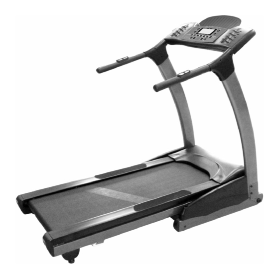
DESCRIPTION LECTRICAL ONFIGURATION Note: Electrical servicing of this treadmill is limited to board level replacement. 1. C249 30533 0 TREADMILL COMPONENTS Safety key: Magnetic key that fits in the Console to activate all functions. b) Console: Interface that controls all functions of the treadmill. -
Page 7: Console
ENERAL NFORMATION 1. CONSOLE Contains touch controls and LCD Display. 2. MAIN CONTROLLER Contains power supply and control circuits. 3. TREADMILL MOTOR Variable speed reversing 0-110 volt DC motor. b) Has three wires red, black and green. If there is DC voltage on the Red wire (M+) the treadmill motor will turn clockwise. -
Page 8: Figure 1 Operational Flowchart
Figure 1 Operational Flowchart... -
Page 9: Operation
OPERATION INDOW ISPLAY 1. OFF MODE When user doesn’t insert the SAFETY KEY on the console, the treadmill enters the OFF Mode and the dot matrix will display” please install safety key to start ” 2. READY MODE When the treadmill is on and the safety key is inserted in console, the dot matrix will display ”... -
Page 10: B F Unction 1. Speed
UNCTION 1. SPEED SPEED and DISTANCE value display in same window and pressing “MODE” button will toggle between them. b) DISPLAY range is 0.0 to 99.9 KPH/MPH. WORK range is 1.0 to 10 MPH. d) Press “FAST” or ”SLOW” to adjust speed, each increment and decrement is 0.1MPH/KPM. -
Page 11: Calories
In RUN Mode, press the “STOP” button the DISTANCE value will still display and save all data. If RUN Mode is entered, the distance will count up again. 4. CALORIES CALORIES divides into COUNT UP and COUNT DOWN. System preset is COUNT UP; if user sets the time then timer is COUNT DOWN. -
Page 12: C F Unction 1. Ready Mode
UNCTION UTTON 1. READY MODE PROGRAM button: User can select “MANUAL” or PROGRAMS 1 to 5 and user 1 to 2. → → → → → → MANUAL → → → → d) START button: When pressing “START” button, there will be 3 second final count down on window display, then machine starts running. - Page 13 b) START button: non-functional. STOP button: press “STOP” button to stop and enter READY Mode. d) MODE button: Exchange display between laps and operation mode. FAST button: Press the button to increase your speed and each increase is 0.1mph/km. If button is pressed continuously then speed increases to MAX SPEED quickly.
-
Page 14: C Alibration
PEED NCLINE ALIBRATION 1. SPEED AND INCLINE CALIBRATION PROCEDURE Power on treadmill. b) Press “START” and “FAST” button at the same time. Inserts the SAFETY KEY on monitor d) Set WHEEL size: Press “FAST” or “SLOW” button to adjust wheel size value to 2.30 in SPEED window. Km/Mile Mode: Press “STOP”... -
Page 15: General
TROUBLESHOOTING WARNING: ALWAYS UNPLUG THE TREADMILL FROM THE ELECTRICAL OUTLET BEFORE SERVICING THE UNIT. 1. GENERAL Do a visual check of all wiring and connections looking for chafed wires or lose connections. b) Make sure any wiring is safely positioned and/or secured away from moving parts. -
Page 16: Troubleshooting Matrix
2. TROUBLESHOOTING MATRIX Condition Reason Solve When turn on power, 1. Power cord isn’t plug into outlet. 1. Plug the power cord into outlet. ON/OFF switch isn’t lit. 2. Power cord isn’t plug into unit. 3. The voltage of outlet is too low. 2. - Page 17 properly. again. 4. 12PIN computer cable is broken. 4. Replace with new 12PIN computer cable. 5. Fuse on controller is blown. 5. Replace with new fuse or controller. 6. Varistor on controller is blown. 6. Replace with new varistor or controller.
- Page 18 After removing safe key, 1. Reed switch of console is broken. 1. Replace with new reed switch or treadmill can’t stop. console. LCD displays not bright, 1. LCD display is broken. 1. Replace with new console and incomplete or imperfect. calibrate it.
- Page 19 seconds. 5. 12PIN computer cable connected improperly. 5. Plug the cable again on controller, connector and console. *Speed sensor cable was 6. 12PIN computer cable is broken. 6. Gray and purple cable got damage, broken,(open) console replace with new cable. can’t receive the speed.
- Page 20 treadmill. 2. Other magnetic field disturbance. 2. Change the position or direction of treadmill. 3. Receiver is broken. 3. Replace with new receiver. After pressing “START” Controller was broken. Replace with new controller and button, the treadmill stop calibrate it. immediately.
- Page 21 SPEED ADJUSTMENT SWITCH/W/CABLE is Speed button just can damaged. press SLOW, can’t press FAST. UP/DOWN button of 1. The connector of INCLINE CABLE (UPPER) 1. Connect the cable again. INCLINE and CONSOLE not connected properly. ADJUSTMENT SWITCH 2. The connector of INCLINE CABLE (UPPER) 2.
- Page 22 Hand pulse lost its 1. Hands not on the hand pulse sensors or only one 1. Two hands hold the hand pulse. function. hand on sensor. (No pulse displayed on 2. The connector of HANDPULSE W/WIRE and 2. Connect the cable again. monitor) Console not connected properly.
- Page 23 Noise under motor cover. 1. Worn brushes or bearings on motor. 1. Replace with new motor. 2. Front roller bearings are defective. 2. Replace with new front roller. 3. Drive belt is misadjusted (too tight or too loose). 3. Adjust motor position. Noise in the rear of the 1.
-
Page 24: Controller Debugging Form
3. CONTROLLER DEBUGGING FORM Indicator LED Function Condition Reason Solve Motor speed Normal on when start is pressed. No input. Check fast/slow wires of 12PIN connector. Fault condition if start is pressed & Replace controller. LED off. POWER Controller power If DC voltage is normal, it would be Voltage is not correct. -
Page 25: Diagrams And Schematics
DIAGRAMS AND SCHEMATICS Figure 2 Console Layout Figure 3 Mechanical Layout... -
Page 26: Figure 4 Main Controller Information & Voltages
Figure 4 Main Controller information & voltages Figure 5 Function JK2 connector on Main Controller... -
Page 27: Figure 6 Wiring Diagram
929-A65 TREADMILL CIRCUIT DIAGRAM CONSOLE 12PIN 700mm Upper Connection PLUG DOWN FAST SLOW CONNECTOR BREAKER AC Switch 100mm Black Wire 100mm Black Wire Incline Motor 150mm White Wire 100mm White Wire Incline VR Black Wire White Wire Red Wire JK3(Incline-VR) DOWN (0~120V) Controller M+ (0 - 110V) -
Page 28: Figure 7 Schematic Diagram
Figure 7 Schematic Diagram... -
Page 29: Appendix A
APPENDIX A 1. TREADBELT ADJUSTMENT The treadbelt has been factory pre-adjusted, however if during the operation: 1 /4 T U R N Figure 8 If Treadbelt slips The treadbelt is too loose: Tighten both rear roller adjusting bolts 1/4 turn clockwise using allen wrench 1/4 TUR N Figure 9 If tread belt shifts too far to the Right a) Set the treadmill speed to 3.5 mph/5.6 km. -
Page 30: Figure 10 If Tread Belt Shifts Too Far To The Left
1/4 TU R N Figure 10 If tread belt shifts too far to the Left a) Set the treadmill speed to 3.5 mph/5.6 km. b) Tighten the left adjusting bolt a 1/4 turn clockwise using allen wrench c) Wait 15 seconds: if no change; turn the right adjusting bolt a 1/4 turn counter-clockwise using allen wrench e) Repeat steps b and c until belt is centered IMPORTANT... -
Page 31: Appendix B
APPENDIX B 1. TREADMILL LUBRICATION Your treadmill should require little maintenance other then periodically applying lubricant. Lubricating under the treadbelt will ensure superior performance and extend its life expectancy. HOW TO CHECK TREADBELT FOR PROPER LUBRICATION Lift one side of the treadbelt and feel the top surface of the treadboard If the surface is (slick) to the touch, then no further lubrication is required If the surface is dry to the touch, apply one packet of lubricant HOW TO APPLY LUBRICANT... -
Page 32: Appendix C
APPENDIX C Tripped Normal Figure 11 Resetting Reset switch 1. RESET SWITCH RESETTING If the red button of reset switch is tripped, it will protrude out from the face of the switch. b) Press in the red button of the switch. If the red button of reset switch is not tripped, that means normal. -
Page 33: Appendix D
APPENDIX D Figure 12 Fuse replacement 1. FUSE REPLACEMENT If your treadmill loses power or will not start, check the fuse located on the motor controller. DANGER: Turn the power switch off and unplug the treadmill to reduce the risk of an electric shock Remove the motor cover Remove and replace the fuse on the motor controller Replace the motor cover... -
Page 34: Appendix E
APPENDIX E 1. SPEED SENSOR ADJUSTMENT If the monitor does not display speed or distance the speed sensor and magnet may be misaligned. Follow these steps to check and realign. Remove the motor cover Check the spacing and alignment between the magnet on the right side of the front roller and the speed sensor on the frame.
Need help?
Do you have a question about the C249 30533 0 and is the answer not in the manual?
Questions and answers