Table of Contents
Advertisement
Quick Links
INSTRUCTION MANUAL XX167-12
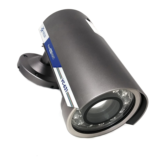
VC-621, VC-621C
ENVIRONMENTAL HOUSING CAMERA
About this manual
Before installing and using the camera, please read this manual carefully.
Be sure to keep it available for later reference.
This installation should be made by a qualified service person and should conform
to the National Electric Code, ANSI/NFPA 70 and all local codes.
Installers should use appropriate hardware mounting materials.
Advertisement
Table of Contents

Related Manuals for Vicon VC-621


Summary of Contents for Vicon VC-621
- Page 1 INSTRUCTION MANUAL XX167-12 VC-621, VC-621C ENVIRONMENTAL HOUSING CAMERA About this manual Before installing and using the camera, please read this manual carefully. Be sure to keep it available for later reference. This installation should be made by a qualified service person and should conform to the National Electric Code, ANSI/NFPA 70 and all local codes.
-
Page 2: Fcc Notice
FCC Notice Note: Complies with Federal Communications Commission Rules & Regulations Part 15, Subpart B for a Class A digital device. WARNING This equipment generates and uses radio frequency energy and if not installed and used properly, that is, in strict accordance with the manufacturer’s instruction, may cause interference to radio and television reception. - Page 3 • Relocate the equipment away from the receiver. • Plug the equipment into a different electrical outlet so that the equipment and receiver are on different branch circuits. If necessary, the user should consult the dealer or an experienced radio/television technician for additional suggestions. The user may find the following booklet prepared by the Federal Communications Commission helpful: “Interference Handbook, Bulletin CIB-2”...
- Page 4 Dimensions : in. (mm)
- Page 5 PRECAUTIONS ■ Do not open or modify Do not open the case except during maintenance and installation, as it may be dangerous and cause damage. ■ Do not put objects inside the unit Make sure that no metal objects or flammable substances get inside the camera.
-
Page 6: Troubleshooting
TROUBLESHOOTING Before sending the camera out for repair, check the items below. If the problem persists after checking these items, contact your service center. ■ If no image appears Is the coaxial cable attached securely? Are the power and voltage normal? Has the iris of the lens inside the camera been adjusted correctly (with the level volume)? Is there adequate illumination? -
Page 7: Specification
SPECIFICATION GENERAL Spec NTSC HQ Interline Transfer CCD 1/3" 410K Pixels Color 1/3" 470K Pixels Color Total Number of Pixels 811(H) x 508(V) 795(H) x 596(V) Scanning System 525 Lines 625 Lines 550TV Lines Horizontal Resolution (BW,No LED)0.04fc, 0.4Lux(Scene) With F1.2 Lens Sensitivity to Light [30IRE] 0.45 Gamma Correction... -
Page 8: Camera Settings
CAMERA SETTINGS ③ IRIS ② 2ND VIDEO ADJUSTMENT CONNECTOR ① DIP SWITCH FUNCTION LENS AE, NOT USED... - Page 9 ※ ADJUSTMENTS 1. Loosen screws with tool provided to remove cap "④" from camera body. 2. Make camera DIP settings according to table. 3. Reassemble cap "④" into camera body. ④ CAP ① DIP Switch Functions (1) Compensating for backlight When back light is too bright (default) Normal setting CAUTION : This can also be adjusted with level volume control (3).
- Page 10 (2) Confirming the iris setting AE (OFF) When fixed iris lens is installed ME (ON) When DC autoiris lens is installed (default) CAUTION: The iris setting is preadjusted as the best condition for use at time of factory shipment; it shouldn't be necessary to change settings. (3) Confirming the White Balance Use this under light source below 2500K and over 9500K of Natrium (Sodium) low color temperature light...
- Page 11 ② Second Video Out Connector (Option) If installer is setting with portable (local) monitor, this connector is used. Be sure to terminate the last device at 75 ohms. ③ Adjusting level volume If the entire image is too dark or bright, or the backlight compensation is not correct even after ①...
-
Page 12: Installation
INSTALLATION ■ CAMERA CONNECTIONS Power Video CAUTION : Check for polarity when using a 12VDC power supply. Input Voltage : 12VDC/24VAC CLASS 2 NOT WET, CLASS 3 WET... - Page 13 ■ LENS FOCUS SETTING ZOOM FOCUS Note: When adjusting the focus, it is recommended that the iris be completely open (a dark condition, either at night or using USE ZOOM & FOCUS a filter) so that the depth of field ADJUST TOOL does not influence the adjustment.
- Page 14 ■ CAMERA ANGLE SETTING ※ ATTENTION 1. Do not rotate ① more than 360˚ 2. Do not twist ② more times than necessary.
- Page 15 Mounting plate configuration in. (mm) Mounting plate diameter Cable access hole...
- Page 16 2 On Yiu Street, Shatin D-24539 Neumuenster New Territories,Hong Kong Phone: +49 (0) 4321 8790 (852) 2145-7118 Fax: +49 (0) 4321 879 47 Fax: (852) 2145-7117 Vicon Part number 8009-8167-12-02 Rev 609 ©Copyright 2009, Vicon Industries Inc. Product specifications subject to change without notice.
Need help?
Do you have a question about the VC-621 and is the answer not in the manual?
Questions and answers