
Summary of Contents for IBM StorageSmart DF1100R
- Page 1 ™ StorageSmart - ProFibre Storage Array RAID Controller Unit - DF1100R Storage Expansion Unit - DF1100J Operator’s Guide SA18-7716-00...
- Page 3 ™ StorageSmart - ProFibre Storage Array RAID Controller Unit - DF1100R Storage Expansion Unit - DF1100J Operator’s Guide SA18-7716-00...
- Page 4 33. First Edition (February 2001) Visit the IBM ProFibre web page at: http://www.ibm.com/storage/profibre © Copyright International Business Machines Corporation 2001. All rights reserved. US Government Users Restricted Rights – Use, duplication or disclosure restricted by GSA ADP Schedule Contract...
-
Page 5: Table Of Contents
Performance Data . . 34 FC-AL Interface Cards . Softcopy Authorization . 34 Switch Card IBM License Agreement for Machine Code . . 34 Identifying Disk Drive Modules . 11 Trademarks . . 35 Chapter 2. Adding Disk Drive Modules Index . - Page 6 ProFibre Storage Array: Operator’s Guide...
-
Page 7: Safety Notices
Do not place the part onto any metal surface. © Copyright IBM Corp. 2001... - Page 8 CAUTION: Do not try to replace and/or exchange the Ni-MH rechargeable battery pack integral to the Battery Backup Unit (BBU) assembly. The Ni-MH battery pack contains small amounts of harmful substances. v Keep the BBU away from fire v Do not expose the BBU to water or rain v Do not attempt to disassemble the BBU v Do not short circuit the BBU v Keep away from children...
-
Page 9: About This Book
The User’s Guide, or equivalent, for your host-system Fibre Channel attachment (for example, your Fibre Channel adapter) v The Site and Hardware Planning Information, or equivalent, for your system v The Problem Solving Guide and Reference, or equivalent, for your system. © Copyright IBM Corp. 2001... -
Page 10: Numbering Convention
Numbering Convention In this book: KB means 1 000 bytes. MB means 1 000 000 bytes. GB means 1 000 000 000 bytes. viii ProFibre Storage Array: Operator’s Guide... -
Page 11: Chapter 1. Introduction
A rack-mounted unit weighs up to 38.5 kg (85 lb) with disk drive modules installed. Do not attempt to lift the unit into the rack unless all the disk drive modules have been removed. CAUTION: Do not use the handles on the fan-and-power-supply to help carry the unit. © Copyright IBM Corp. 2001... -
Page 12: The Profibre Storage Array
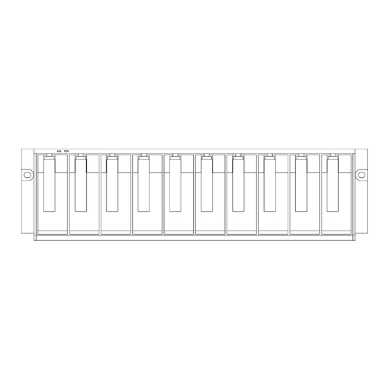
The ProFibre Storage Array The ProFibre Storage Array comprises a controller unit and up to seven expansion units. Each unit in a ProFibre Storage Array is 3 EIA units high and is suitable for mounting in an industry standard (EIA) 19-inch rack. Figure 1. -
Page 13: Controls And Lights
On the back of the backplane of a controller unit are connectors for two fan-and-power-supply assemblies 2 , two RAID FF cards 3 , and a switch card 4 . An expansion unit has connectors for two FC-AL Interface Cards 5 instead of two RAID FF cards 3 . -
Page 14: Disk Drive Modules
Figure 2. Indicator Lights The following lights are on the front of the units. Unit Power light 1 The Unit Power light, which is green, comes on continuously when power is being supplied to the unit by one or both of the fan-and-power-supply assemblies within the unit. -
Page 15: Fan-And-Power-Supply Assemblies
The disk drive module is not powered on. The disk drive module is ready but not active. Flashing This disk drive module is active with a command in progress. 2 Check light The Check light, which is amber, shows the following conditions: Normal operating condition. - Page 16 Figure 5. Fan-and-Power-Supply Assembly Lights and Switch A fan-and-power-supply assembly has the following lights and switch: AC PWR light 1 The AC PWR light, which is green, comes on when the mainline power supply is connected to the fan-and-power-supply assembly. DC PWR light 2 The DC PWR light, which is green, comes on when this fan-and-power-supply assembly is supplying power to the ProFibre...
-
Page 17: Raid Ff Cards
RAID FF Cards Two RAID FF 1 cards are installed in the back of a ProFibre Storage Array Controller Unit (see Figure 6 Figure 6. RAID FF Card Assemblies A RAID FF card has the following lights: Figure 7. RAID FF Card Assembly Lights Power light 1 The Power light, which is green, is lit when dc power is applied to the RAID FF card. -
Page 18: Fc-Al Interface Cards
HOST FC Status light 4 This Status light, which is amber, is lit when there is no valid Fibre Channel connection through the HOST port, or when the port is inactive while it is waiting for failover. OUT FC Status light 5 This Status light, which is amber, is lit when there is no valid Fibre Channel connection through the OUT port, or when the port is inactive while it is waiting for failover. -
Page 19: Switch Card
Power light 2 The green Power light is lit when the voltage is correct. Card Fault light 3 The amber Card Fault light is lit when an error condition has been detected. Switch Card A switch card 1 is installed in the back of a unit of the ProFibre Storage Array. Figure 10. - Page 20 Figure 11. Switch Card (with or without BBU) The switch card contains two separate switches: FC-AL Address switch 5 This switch can be set to a value between 0 and 7. It controls the FC-AL addresses used by the ProFibre Storage Array. For example, if the switch is set to 5, the FC-AL address of the disks in slots 1 to 10 are then 50 to 59 (hexadecimal).
-
Page 21: Identifying Disk Drive Modules
Identifying Disk Drive Modules You can identify a disk drive module by the serial number that appears on a label 1 on the front of the module: Figure 12. Disk Drive Module Label This label also shows the capacity of the disk drive. Each disk drive module also has a FC-AL address that is related to its position in the ProFibre Storage Array unit. - Page 22 ProFibre Storage Array: Operator’s Guide...
-
Page 23: Chapter 2. Adding Disk Drive Modules
After you have added a disk drive module to the unit, you must add it into your system software configuration by using the system programs. Refer to the SANArray Manager Client Software for Mylex External Disk Array Controllers: Installation and User Manual for guidance on how to do this. © Copyright IBM Corp. 2001... -
Page 24: Before Adding A Disk Drive Module
Before Adding a Disk Drive Module Identify the slot for the new disk drive module by using the configuration planning information for your system. A dummy disk drive module should be in the slot. See Figure 14. Figure 14. Dummy Disk Drive Module To Add a Disk Drive Module 1. - Page 25 2. With one hand giving support to the base of the disk drive module and the other hand holding the handle 1 , insert the module and push it into the slot. When the handle touches the front surface of the unit, the module stops. Note that the module is not yet fully inserted.
- Page 26 4. Verify that the disk drive module that you have just installed is aligned with the sides of the unit, and that no gap exists between this module and the modules that are next to it. Verify also that the front edge of this disk drive module aligns with the front edges of the modules next to it.
-
Page 27: Chapter 3. Exchanging Disk Drive Modules And Fan-And-Power-Supply Assemblies
FC-AL disk drive module. It also shows the capacity of the disk drive module. See Figure 19. Figure 19. Disk Drive Module Handle and Capacity The replacement disk drive module should have at least the capacity of the disk drive module being replaced. © Copyright IBM Corp. 2001... -
Page 28: Before Exchanging A Disk Drive Module
Attention: v Disk drive modules are fragile. Handle them with care. Keep them well away from strong magnetic fields. v Any slot that has no disk drive module installed must contain a dummy disk drive module. The dummy module ensures that the correct airflow is maintained around the disk drive modules in the other slots. - Page 29 Figure 21. Removing a Disk Drive Module Attention: The fan speed may increase. Do not leave the slot empty for more than 30 minutes; if you do, the unit, and the disk drive modules, may overheat and be damaged. 4. With one hand giving support to the base of the replacement module and the other hand holding the handle 1 , insert the module and push it into the slot.
- Page 30 Attention: The speed of the fans may decrease. Figure 23. Closing the Handle 6. Verify that the disk drive module that you have just installed is aligned with the sides of the unit and that no gap exists between this module and the modules that are next to it.
-
Page 31: Exchanging A Fan-And-Power-Supply Assembly
Figure 24. Disk Drive Module Lights 8. Restore the disk drive module into your system, using the system programs. Exchanging a Fan-and-Power-Supply Assembly You can exchange a faulty fan-and-power-supply assembly if: v You have a correct spare fan-and-power-supply assembly and, v Another fan-and-power-supply assembly is still present in this unit. -
Page 32: Before Exchanging A Fan-And-Power-Supply Assembly
Before Exchanging a Fan-and-Power-Supply Assembly Check the lights on this fan-and-power-supply assembly (see: “Fan-and-Power- Supply Assemblies” on page 5). Ensure that the DC On/Standby switch is on. Attention: If the Check light is not on, do not exchange the power-supply assembly;... - Page 33 2. Unplug the mainline power cable from the failing fan-and-power-supply assembly. Figure 27. Unplugging the Mainline Power Cable CAUTION: Ensure that the mainline power cable has been removed from the failing fan-and-power-supply assembly, and the AC PWR light 1 is off, before continuing.
- Page 34 3. Unscrew the two thumbscrews on the fan-and-power-supply assembly. Figure 28. Unscrewing the Thumbscrews on the Fan-and-Power-Supply Assembly ProFibre Storage Array: Operator’s Guide...
- Page 35 4. Pull the fan-and-power-supply assembly from the unit. Attention: The speed of the other fan in the unit may increase. Figure 29. Removing the Fan-and-Power-Supply Assembly Attention: Do not leave the space empty for more than 30 minutes; if you do, the unit, and the disk drive modules may overheat and be damaged.
- Page 36 5. Push the replacement fan-and-power-supply assembly fully into the unit. Attention: The speed of the other fan in the unit may decrease. Figure 30. Inserting a Replacement Fan-and-Power-Supply Assembly 6. Tighten the two thumbscrews by turning them clockwise. Figure 31. Tightening the Screws on a Fan-and-Power-Supply Assembly ProFibre Storage Array: Operator’s Guide...
- Page 37 7. Plug the mainline power cable into the new fan-and-power-supply assembly. Ensure that the AC PWR light 1 comes on. DANGER Do not plug the power supply cord into the fan-and-power-supply assembly until the unit has been completely installed and its retaining screws have been tightened.
- Page 38 8. Set the DC On/Standby switch 1 on the new fan-and-power-supply assembly to ON. Ensure that the DC PWR light 2 comes on. Attention: Note that the fan speeds may decrease. Figure 33. Fan-and-Power-Supply DC On/Standby Switch ProFibre Storage Array: Operator’s Guide...
- Page 39 9. If the amber CHK light 1 comes on, verify that the new fan-and-power- supply assembly is correctly installed. If it is correctly installed, refer to the StorageSmart - ProFibre Storage Array, RAID Controller Unit - DF1100R, Storage Expansion Unit - DF1100J: Service Guide, GY18-2409 for information about determining the cause of a problem.
- Page 40 ProFibre Storage Array: Operator’s Guide...
-
Page 41: Chapter 4. Reporting Problems
You can report problems to: Technical Support Hours: 6:00am - 6:00pm Pacific Time Monday - Friday (Excluding U.S. holidays) 877.731.4461 (Toll-Free, U.S/Canada only) 510.608.2200 (International) Fax: 510.745.7715 email: profibre@us.ibm.com web - problem reporting form: http://www.storage.ibm.com/storagesmart/techfeedback.htm © Copyright IBM Corp. 2001... - Page 42 ProFibre Storage Array: Operator’s Guide...
-
Page 43: Notices
Consult your local IBM representative for information on the products and services currently available in your area. Any reference to an IBM product, program, or service is not intended to state or imply that only that IBM product, program, or service may be used. Any functionally equivalent product, program, or service that does not infringe any IBM intellectual property rights may be used instead. -
Page 44: Performance Data
Transfer the original unaltered copy of the documentation when you transfer the related IBM product (which may be either machines you own, or programs, if the program’s license terms permit a transfer). You must, at the same time, destroy all other copies of the documentation. -
Page 45: Trademarks
You may not, for example, do any of the following: v Otherwise copy, display, transfer, adapt, modify, or distribute in any form, Machine Code, except as IBM may authorize in a Machine user documentation v Reverse assemble, reverse compile, or otherwise translate the Machine Code,... - Page 46 ProFibre Storage Array: Operator’s Guide...
-
Page 47: Index
RAID FF card RAID FF card 8 lights 7 HOST FC Status light, RAID FF card 8 Rotary switch interface card 10 identifying disk drive modules 11 interface card lights 8 serial number, machine 31 © Copyright IBM Corp. 2001... - Page 48 ProFibre Storage Array: Operator’s Guide...
- Page 49 Thank you for your responses. May we contact you? h Yes h No When you send comments to IBM, you grant IBM a nonexclusive right to use or distribute your comments in any way it believes appropriate without incurring any obligation to you. Name...
- Page 50 UNITED STATES BUSINESS REPLY MAIL FIRST-CLASS MAIL PERMIT NO. 40 ARMONK, NEW YORK POSTAGE WILL BE PAID BY ADDRESSEE Mylex, an IBM Company Information Development, Dept 6IMA 5400 Airport Blvd Boulder, CO 80301 _ _ _ _ _ _ _ _ _ _ _ _ _ _ _ _ _ _ _ _ _ _ _ _ _ _ _ _ _ _ _ _ _ _ _ _ _ _ _ _ _ _ _ _ _ _ _ _ _ _ _ _ _ _ _ _ _ _ _ _ _ _ _ _ _ _ _ _ _ _ _ _ _ _ _ _ _ _ _ _ _ _ _ _ _ _ _ _ _...
- Page 52 Printed in the United States of America on recycled paper containing 10% recovered post-consumer fiber. SA18-7716-00...
Need help?
Do you have a question about the StorageSmart DF1100R and is the answer not in the manual?
Questions and answers