BEA IS40 User Manual
Combined active infrared (ir) and microwave sensor
Hide thumbs
Also See for IS40:
- Installation manual (10 pages) ,
- Manual (9 pages) ,
- User manual (6 pages)
Table of Contents
Advertisement
Quick Links
Download this manual
See also:
Installation Manual
1
DESCRIPTION
- The IS40 uses
Microwave technology
for motion detection
and Active Infrared
technology for
presence detection.
2
3
4
5
2
SPECIFICATIONS
DESCRIPTION
SENSOR TILT ANGLE
SUPPLY VOLTAGE
MAIN FREQUENCY
POWER CONSUMPTION
RELAY OUTPUT
- Max. Voltage
- Max. Current
- Max Switching Power
INSTALLATION HEIGHT
TEMPERATURE RANGE
PROTECTION DEGREE
NORM CONFORMITY
DIMENSIONS (D X W X H)
MATERIAL
- Housing
- Face
COLOR
- Housing
- Face
CABLE LENGTH
TECHNOLOGY
RADIATED FREQUENCY
RADIATED POWER DENSITY
DETECTION MODE
MAXIMUM DETECTION FIELD
OUTPUT HOLD TIME
REACTION TIME
MINIMUM TARGET SPEED
LED SIGNAL
RADAR ANGLE / SENSOR ANGLE
75.5695.01 EN 20120113
IS40 / IS40XL
Electromagnetic compatibility (EMC) according to 2004/108/EEC, R&TTE: 1999/5/EC
MICROWAVE DOPPLER RADAR
IS40: 13 ft x 16 ft (4m x 5m)
IS40XL: 13 ft x 6.5 ft (4m x 2m)
2 in/sec (5cm/sec) in sensor axis
-8° to 22° (relative to sensor front face)
COMBINED ACTIVE INFRARED (IR) AND MICROWAVE SENSOR
IS40: for normal to high mounting 8 ft - 16 ft (2.5 - 6 m)
1
IS40 XL: for low mounting 6.5 ft - 11.5 ft (2 - 3.5 m)
SPECIFICATION
12 to 24VAC ±10%
12 to 24VDC +30% / -5%
2 Relays with switch-over contact (voltage free)
60 VDC / 125 VAC
30W (DC) / 60VA (AC)
IS40: 8 ft - 16 ft (2.5 - 6 m)
IS40XL: 6.5 ft - 11.5 ft (2 - 3.5 m)
-22°F ( -30°C) to + 140°F (60°C)
IP65 / NEMA 4
5 in. X 4 in. X 3.75 in. (127mm x 102mm x 96mm)
Polycarbonate
Transparent Purple
32 feet (10m)
24.175 GHz
< 5 mW/cm²
Motion
0.5 sec. to 9 sec.
100ms
Green = Activation Relay
IS40 / IS40XL
USER'S GUIDE
6
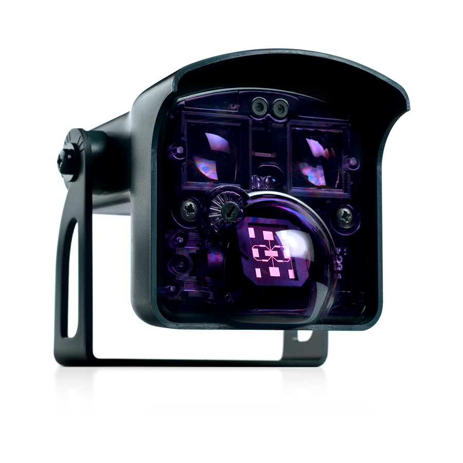
1. IR angle indicator
2. LED's
3. IR emitters
4. Radar angle adjustment
dial
7
5. Radar detection antenna
6. Sensor angle adjustment
7. Bracket
8. Cable
8
15° to 45°
50 to 60Hz
< 3.5W
1A (resistive)
ABS
Black
INFRARED
875 nm
< 250mW/m²
Presence
IS40: 10 ft x 10 ft (3m x 3m)
IS40XL: 7.5 ft x 7.5 ft (2.3m x 2.3m)
0.5 sec.
250ms
0 in/sec (0cm/sec)
Red = Presence Relay
15°, 30°, 45°
Page 1 of 9
Advertisement
Table of Contents

Related Manuals for BEA IS40


Summary of Contents for BEA IS40
-
Page 1: Specifications
COMBINED ACTIVE INFRARED (IR) AND MICROWAVE SENSOR DESCRIPTION IS40: for normal to high mounting 8 ft - 16 ft (2.5 - 6 m) IS40 XL: for low mounting 6.5 ft - 11.5 ft (2 - 3.5 m) - The IS40 uses... -
Page 2: Installation Tips
Ensure compliance with all applicable safety standards upon completion of installation. DO NOT attempt any internal repair of the sensor. All repairs and/or component replacements must be performed by BEA Inc. Unau- thorized disassembly or repair: 1. May jeopardize personal safety and may expose one to the risk of electrical shock. -
Page 3: Sensor Angle
WIRING AND RELAY CONFIGURATION 12-24 V POWER BLACK AC-DC WHITE Green LED WIRING GREEN ACTIVATION RELAY Motion YELLOW WHITE/BLACK Red LED GREEN/BLACK PRESENCE RELAY Presence YELLOW/BLACK RELAY Activation Presence Description Active Passive CONFIGURATION Relay Relay Active Passive Detection Passive Active Passive Passive Detection... - Page 4 Maximum Mounting Height IS40XL 11. 5 ft IS40 16 ft * Dimensions are approximate Use of BEA Spotfinder may be utilized to locate IR field. 12” MICROWAVE FIELD ADJUSTMENTS By turning this dial, the radar field Adjust the Microwave field...
- Page 5 MICROWAVE FIELD TILT ANGLE The total angle is the sum of the sensor angle and the radar field angle. All detection field dimensions were measured in optimal conditions and a sensitivity value of 7. IS40 8 ft 8 ft 11.5 ft 8 ft 11.5 ft...
-
Page 6: Function Description
3: Low ‘Pedestrian/Parallel traffic’ Rejection 6: Extra High ‘Pedestrian/Parallel traffic’ Rejection + Interference Immunity + Interference Immunity OUTPUT CONFIGURATION PRESENCE RELAY IS40 / IS40XL 0 - 6: ALL MODES Activates when object is in presence zone. OUTPUT ACTIVATION RELAY IS40 / IS40XL... - Page 7 REMOTE CONTROL PARAMETERS (CONTINTUED) IR / Presence Settings (Continued) IR PATTERN AVAILABLE TARGET SIZE SIZE DOOR The target (Target Size) can vary location within the field (IR Pattern Size) DOOR DOOR DOOR DOOR DOOR DOOR DOOR DOOR FACTORY VALUES 75.5695.01 EN 20120113 Page 7 of 9...
-
Page 8: 14 Troubleshooting
REMOTE CONTROL PARAMETERS (CONTINUED) Check parameter values The number of green flashes QUESTION A VALUE indicates the value of the chosen parameter. SENSOR SETUP SEQUENCE / FACTORY VALUES / ACCESS CODE IMPORTANT: ENSURE TO SAVE ANY CHANGES DURING THE ADJUSTMENT Parameter Value SESSION VIA PRESSING LOCK LOCK. - Page 9 Do not leave problems unresolved. If a satisfactory solution cannot be achieved after troubleshooting a problem, please call BEA, Inc. If you must wait for the following workday to call BEA, leave the door inoperable until satisfactory repairs can be made. Never sacrifice the safe operation of the automatic door or gate for an incomplete solution.
Need help?
Do you have a question about the IS40 and is the answer not in the manual?
Questions and answers