
Related Manuals for Huawei AP7050DE


Summary of Contents for Huawei AP7050DE
- Page 1 AP7050DE Hardware Installation and Maintenance Guide Issue Date 2016-04-15 HUAWEI TECHNOLOGIES CO., LTD.
- Page 2 Notice The purchased products, services and features are stipulated by the contract made between Huawei and the customer. All or part of the products, services and features described in this document may not be within the purchase scope or the usage scope. Unless otherwise specified in the contract, all statements, information, and recommendations in this document are provided "AS IS"...
-
Page 3: About This Document
AP7050DE Hardware Installation and Maintenance Guide About This Document About This Document Intended Audience This document describes hardware features of the AP7050DE and provides basic installation methods. This document is intended for: Network planning engineers Hardware installation engineers Commissioning engineers... - Page 4 Change History Changes between document issues are cumulative. The latest document issue contains all changes made in previous issues. Issue 01 (2016-04-10) Initial commercial release Issue 01 (2016-04-15) Huawei Proprietary and Confidential Copyright © Huawei Technologies Co., Ltd.
-
Page 5: Table Of Contents
5.1 On-site Cable Assembly and Installation........................27 5.1.1 Cable Assembly Precautions............................. 27 5.1.2 Assembling Power Cables............................28 5.1.3 Assembling Ethernet Cables............................36 5.1.4 Installing Cable Accessories............................50 5.1.5 Replacing the Mold of the Crimping Tool.........................66 Issue 01 (2016-04-15) Huawei Proprietary and Confidential Copyright © Huawei Technologies Co., Ltd. - Page 6 5.4.4 Engineering Labels for User Cables.......................... 95 5.4.5 Engineering Labels for Power Cables........................96 5.5 Guide to Using Optical Modules..........................99 5.6 Fault Tag..................................102 5.7 Installation Checklist..............................103 Issue 01 (2016-04-15) Huawei Proprietary and Confidential Copyright © Huawei Technologies Co., Ltd.
-
Page 7: Issue
Product Overview About This Chapter The AP7050DE supports HT80 on both the 2.4 GHz and 5 GHz frequency bands and MU- MIMO (4SU-4MU), provides comprehensive service support capabilities, and features high reliability, high security, simple network deployment, automatic AC discovery and configuration, as well as real-time management and maintenance, which meets network deployment requirements. -
Page 8: Device Structure
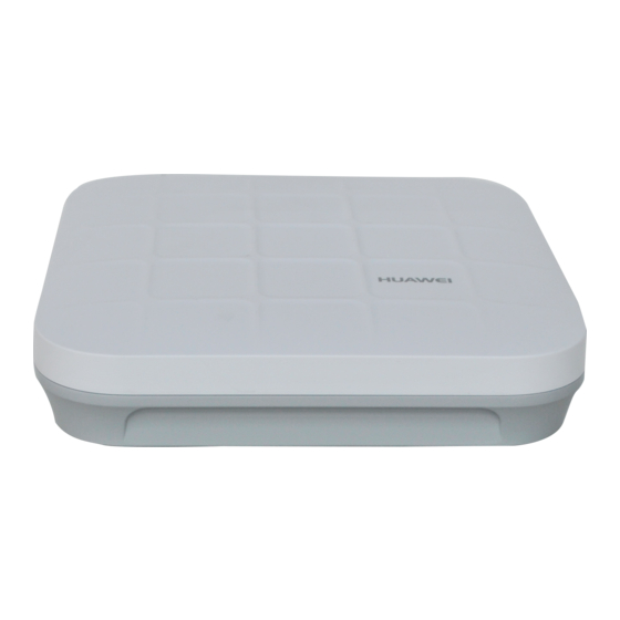
AP7050DE Hardware Installation and Maintenance Guide 1 Product Overview 1.1 Device Structure Figure 1-1 shows the appearance of the AP7050DE. Figure 1-1 Appearance of the AP7050DE Table 1-1 describes interfaces on the AP7050DE. Table 1-1 Descriptions of interfaces Name Description... -
Page 9: Indicator Description
Hardware Installation and Maintenance Guide 1 Product Overview Name Description Security slot Connects to a security lock. 1.2 Indicator Description The AP7050DE provides only one indicator, as shown in Figure 1-2. NOTE Indicator colors may vary slightly at different temperature. Figure 1-2 Indicator Indicator... - Page 10 AC (before the CAPWAP link is established). l The AP fails to go online on the AC (the CAPWAP link disconnects). Issue 01 (2016-04-15) Huawei Proprietary and Confidential Copyright © Huawei Technologies Co., Ltd.
-
Page 11: Basic Specifications
The fault cannot be automatically rectified and must be rectified manually. 1.3 Basic Specifications Table 1-3 provides basic specifications of the AP7050DE. Table 1-3 Basic specifications Item Description Technical Dimensions (H x 53 mm x 220 mm x 220 mm... -
Page 12: Ordering Information
To place an order, contact technical support personnel. Part Number Description 50082932 Wireless LAN Equipment,AP7050DE,11ac,Double Frequency,Built-in Antenna 50082933 Wireless LAN Equipment,AP7050DE-USA,11ac,Double Frequency,Built-in Antenna 50082934 Wireless LAN Equipment,AP7050DE-DC,11ac,Double Frequency,Built-in Antenna Issue 01 (2016-04-15) Huawei Proprietary and Confidential Copyright © Huawei Technologies Co., Ltd. -
Page 13: Ap Installation
2.4 Determining the Installation Position 2.5 Installing the AP 2.6 Cable Connection 2.7 Connecting the Security Lock 2.8 Checking the Device After Installation 2.9 Powering on the AP Issue 01 (2016-04-15) Huawei Proprietary and Confidential Copyright © Huawei Technologies Co., Ltd. -
Page 14: Preparing For Installation
To install APs, prepare tools listed in Table 2-1. Table 2-1 Tools Phillips screwdriver Protective gloves ESD gloves Slip-proof glove Marker Hammer drill Claw hammer Diagonal pliers Wire stripper Issue 01 (2016-04-15) Huawei Proprietary and Confidential Copyright © Huawei Technologies Co., Ltd. -
Page 15: Installation Flowchart
RJ45 crimping tool Cable cutter Network cable tester Multimeter Ladder Safety helmet Safety belt Anti-skid shoes 2.2 Installation Flowchart The following figure shows the process for installing an AP. Issue 01 (2016-04-15) Huawei Proprietary and Confidential Copyright © Huawei Technologies Co., Ltd. -
Page 16: Unpacking The Equipment
Adjustable buckle Expansion screws Quick start guide Warranty card MAC address label SN label NOTE If a PoE adapter is required, you need to purchase it separately. Issue 01 (2016-04-15) Huawei Proprietary and Confidential Copyright © Huawei Technologies Co., Ltd. -
Page 17: Determining The Installation Position
Do not install the AP in an environment with high temperature, dust, poisonous gases, flammable or explosive objects, electromagnetic interference (from a radar station, radio station, or substation), unstable voltage, violent shakes, or strong noise. Issue 01 (2016-04-15) Huawei Proprietary and Confidential Copyright © Huawei Technologies Co., Ltd. -
Page 18: Installing The Ap
Use a 6 mm drill bit to drill 25 mm to 30 mm deep holes in the drilling positions. Hammer the expansion tubes into the holes until the expansion tubes are completely embedded into the wall. Issue 01 (2016-04-15) Huawei Proprietary and Confidential Copyright © Huawei Technologies Co., Ltd. -
Page 19: Installing The Device On A Ceiling
The screws provided for ceiling-mounting of APs are 30 mm long and can be used to fix an AP on a ceiling not thicker than 15 mm. To install APs on thicker ceilings, you need to purchase longer screws. Issue 01 (2016-04-15) Huawei Proprietary and Confidential Copyright © Huawei Technologies Co., Ltd. -
Page 20: Installing The Device On A T-Rail
Remove two ceiling tiles around the T-rail, use screws to fix the adjustable buckle to the mounting bracket, hook the adjustable buckle to the T-rail, and secure the screw on the adjustable buckle to fasten the mounting bracket and T-rail. Issue 01 (2016-04-15) Huawei Proprietary and Confidential Copyright © Huawei Technologies Co., Ltd. -
Page 21: Cable Connection
Ensure that the AP is correctly installed on the mounting bracket and there must be 200 mm space above and around the AP for maintenance. 2.6 Cable Connection Figure 2-3 describes the cable connections. Issue 01 (2016-04-15) Huawei Proprietary and Confidential Copyright © Huawei Technologies Co., Ltd. - Page 22 AP7050DE Hardware Installation and Maintenance Guide 2 AP Installation Figure 2-3 Appearance of the AP7050DE Table 2-3 Cable connections Cable or Device Description USB flash drive Connects to a USB flash drive to extend the storage space of the AP. The USB2.0 standard is supported.
- Page 23 Cable tie tails should be cut smoothly and evenly. Labels or nameplates must be attached to the cables after they are installed. Connecting USB Flash Drivers To ensure compatibility between USB flash drives and devices, use Huawei-certified USB flash drives (listed in Table 2-4) to configure the Huawei devices.
-
Page 24: Connecting The Security Lock
Fasten the cable of the security lock to an immovable object around. Insert the security lock into the security slot and lock it. Security lock Lock hole NOTE You need to purchase the security lock separately. Issue 01 (2016-04-15) Huawei Proprietary and Confidential Copyright © Huawei Technologies Co., Ltd. -
Page 25: Checking The Device After Installation
After the AP installation is complete, observe indicator on the AP to determine the system running status. For details, see 1.2 Indicator Description. NOTE Do not frequently power on and off the device. Issue 01 (2016-04-15) Huawei Proprietary and Confidential Copyright © Huawei Technologies Co., Ltd. -
Page 26: Logging In To The Device
3 Logging In to the Device Logging In to the Device About This Chapter 3.1 Logging In to the Device Using STelnet/Telnet 3.2 Logging In to the Device Through the Console Port Issue 01 (2016-04-15) Huawei Proprietary and Confidential Copyright © Huawei Technologies Co., Ltd. -
Page 27: Logging In To The Device Using Stelnet/Telnet
Step 4 Enter the user name and password as prompted to log in to the user interface. ----End 3.2 Logging In to the Device Through the Console Port Issue 01 (2016-04-15) Huawei Proprietary and Confidential Copyright © Huawei Technologies Co., Ltd. - Page 28 Parity: None Stop bits: 1 Flow control (F): None Step 3 Press Enter and enter the default user name admin and password admin@huawei.com as prompted to log in to the user view. (The following information is only for reference.) Login authentication...
-
Page 29: Hardware Failures
Hardware Installation and Maintenance Guide 4 Hardware Failures Hardware Failures About This Chapter This section describes common methods for troubleshooting typical hardware faults. 4.1 A Device Fails to Be Powered On Issue 01 (2016-04-15) Huawei Proprietary and Confidential Copyright © Huawei Technologies Co., Ltd. -
Page 30: A Device Fails To Be Powered On
The line is faulty (the network cable or distribution frame is damaged). l The device is faulty. Issue 01 (2016-04-15) Huawei Proprietary and Confidential Copyright © Huawei Technologies Co., Ltd. - Page 31 4. If the device still cannot be powered on, the device itself is faulty. Contact technical support personnel or Huawei agent and ask them to replace the device. Issue 01 (2016-04-15) Huawei Proprietary and Confidential Copyright © Huawei Technologies Co., Ltd.
-
Page 32: Appendix
5.2 Environmental Requirements for Device Operation 5.3 Equipment Grounding Specifications 5.4 Engineering Labels for Cables 5.5 Guide to Using Optical Modules 5.6 Fault Tag 5.7 Installation Checklist Issue 01 (2016-04-15) Huawei Proprietary and Confidential Copyright © Huawei Technologies Co., Ltd. -
Page 33: On-Site Cable Assembly And Installation
Precautions for Assembly Use dedicated tools or tools delivered by Huawei and follow the methods given here during assembly. Hold terminals of cables instead of pulling the cables themselves when installing or removing cable components. -
Page 34: Assembling Power Cables
Step 1 Based on the cross-sectional area of the cable conductor, strip a length of insulation coating C to expose the conductor D of length L1, as shown in Figure 5-2. The recommended values of L1 are listed in Table 5-1. Issue 01 (2016-04-15) Huawei Proprietary and Confidential Copyright © Huawei Technologies Co., Ltd. - Page 35 When you strip a power cable, do not damage the conductor of the cable. l If the bare crimping terminal is not provided by Huawei, the value of L1 is 1 mm (0.04 in.) to 2 mm (0.08 in.) greater than the value of L.
- Page 36 Step 5 Push the heat shrink tubing (A) toward the connector until the tube covers the crimped part, and then use a heat gun to heat the tube, as shown in Figure 5-5. Issue 01 (2016-04-15) Huawei Proprietary and Confidential Copyright © Huawei Technologies Co., Ltd.
- Page 37 Figure 5-6 Components of a JG terminal and a power cable A. JG terminal B. Heat-shrinkable tubing C. Insulation layer of a power D. Conductor of a power cable cable Issue 01 (2016-04-15) Huawei Proprietary and Confidential Copyright © Huawei Technologies Co., Ltd.
- Page 38 NOTICE l When you strip a power cable, do not damage the conductor of the cable. l If the bare crimping terminal is not provided by Huawei, you can adjust the value of L as required. Figure 5-7 Stripping a power cable (JG terminal)
- Page 39 Step 5 Push the heat shrink tubing toward the connector until the tube covers the crimped part, and then use a heat gun to heat the tube, as shown in Figure 5-10. Figure 5-10 Heating the heat shrink tubing (JG terminal) Issue 01 (2016-04-15) Huawei Proprietary and Confidential Copyright © Huawei Technologies Co., Ltd.
- Page 40 5-12. The recommended values of L1 are listed in Table 5-3. NOTICE When you strip a power cable, do not damage the conductor of the cable. Figure 5-12 Stripping a power cable (cord end terminal) Issue 01 (2016-04-15) Huawei Proprietary and Confidential Copyright © Huawei Technologies Co., Ltd.
- Page 41 Figure 5-13 Putting the cord end terminal onto the conductor Step 3 Crimp the joint parts of the cord end terminal and the conductor, as shown in Figure 5-14. Issue 01 (2016-04-15) Huawei Proprietary and Confidential Copyright © Huawei Technologies Co., Ltd.
-
Page 42: Assembling Ethernet Cables
5.3 (0.21) 16 (0.025) 6 (0.24) 25 (0.039) 8.7 (0.34) 35 (0.054) 10 (0.39) ----End 5.1.3 Assembling Ethernet Cables Assembling the Shielded RJ45 Connector and Ethernet Cable Issue 01 (2016-04-15) Huawei Proprietary and Confidential Copyright © Huawei Technologies Co., Ltd. - Page 43 Step 2 Remove a 30 mm (1.18 in.) long section of the jacket, cut off the nylon twine inside the jacket, and cut a no more than 5 mm (0.20 in.) cleft in the jacket, as shown in Figure 5-17. Issue 01 (2016-04-15) Huawei Proprietary and Confidential Copyright © Huawei Technologies Co., Ltd.
- Page 44 Along the edge of the metal shell, cut off the aluminum foil shield layer and ensure that there is no surplus copper wire. The exposed twisted-pair cable is about 20 mm (0.79 in.) long, as shown in Figure 5-19. Issue 01 (2016-04-15) Huawei Proprietary and Confidential Copyright © Huawei Technologies Co., Ltd.
- Page 45 Step 6 Align the four pairs of cables in the holder, as shown in Figure 5-22. The connections between the wires and the pins are shown in Figure 5-23 and listed in Table 5-5. Issue 01 (2016-04-15) Huawei Proprietary and Confidential Copyright © Huawei Technologies Co., Ltd.
- Page 46 Table 5-5 Connections between wires and pins (using a straight-through cable as an example) Matching Pins of Wires Wire Color White-Orange Orange White-Green Blue White-Blue Green White-Brown Issue 01 (2016-04-15) Huawei Proprietary and Confidential Copyright © Huawei Technologies Co., Ltd.
- Page 47 Step 9 Push the metal shell toward the connector body until the wire holder and the connector body are engaged completely. Crimp the connector, as shown in Figure 5-26. Issue 01 (2016-04-15) Huawei Proprietary and Confidential Copyright © Huawei Technologies Co., Ltd.
- Page 48 Step 11 To complete the assembly of the other end, repeat Step 1 through Step ----End Assembling an Unshielded RJ45 Connector and Ethernet Cable Context Figure 5-28 shows the components of an unshielded RJ45 connector and cable. Issue 01 (2016-04-15) Huawei Proprietary and Confidential Copyright © Huawei Technologies Co., Ltd.
- Page 49 Table 5-6. Figure 5-30 Connections between wires and pins (unit: mm (in.)) White-Orange Orange White-Green Blue White-Blue Green White-Brown Pin 8 Brown Pin 1 Issue 01 (2016-04-15) Huawei Proprietary and Confidential Copyright © Huawei Technologies Co., Ltd.
- Page 50 The contact strips must be parallel to each other, with an offset of less than ± 5°. The top margin of a strip must be parallel to the axis of the connector, with an offset of less than ± 10°. Issue 01 (2016-04-15) Huawei Proprietary and Confidential Copyright © Huawei Technologies Co., Ltd.
- Page 51 Figure 5-33 Contact strips of the same height Step 2 Hold an RJ45 connector and turn it 45°. Observe the top edges of the metal contact strips. Figure 5-34 shows an unqualified piece. Issue 01 (2016-04-15) Huawei Proprietary and Confidential Copyright © Huawei Technologies Co., Ltd.
- Page 52 Step 5 Hold the connector with the side facing towards you, and check whether you can see the cross-sections of the wires. Ensure that the ends of the wires are in good contact with the edge Issue 01 (2016-04-15) Huawei Proprietary and Confidential Copyright © Huawei Technologies Co., Ltd.
- Page 53 Testing the Connection of Assembled Cables Context Huawei provides two types of Ethernet cables: straight-through cables and crossover cables. Straight-through cables are connected in a one-to-one manner. They are used to connect terminals such as a computer or switch to network devices.
- Page 54 Turn the switch to the S position to slow down lighting of the indicators so that you can see the indicators more clearly, as shown in Figure 5-39. Issue 01 (2016-04-15) Huawei Proprietary and Confidential Copyright © Huawei Technologies Co., Ltd.
- Page 55 (right) section of the tester, the indicators turn on in the sequence of 3-6-1-4-5-2-7-8-G. If the indicators do not come on in this sequence, the Ethernet cable is unqualified. Issue 01 (2016-04-15) Huawei Proprietary and Confidential Copyright © Huawei Technologies Co., Ltd.
-
Page 56: Installing Cable Accessories
For example, in this document, the adapters of cable connectors have separate interfaces. In the actual situation, the adapters may have interfaces fixed on equipment. Use dedicated tools provided or specified by Huawei and follow the installation procedure described here. - Page 57 Sharp objects must not touch cable wiring to prevent damage to cables. To protect power cables, route power cables of the active and standby power modules separately. Installing Power Adapters Installing the OT Terminal Issue 01 (2016-04-15) Huawei Proprietary and Confidential Copyright © Huawei Technologies Co., Ltd.
- Page 58 Figure 5-43 Installing an OT terminal, showing the orientation of crimping sleeve Place the spring washer and flat washer in turn, mount a matching screw, and fasten it clockwise, as shown in Figure 5-44. Issue 01 (2016-04-15) Huawei Proprietary and Confidential Copyright © Huawei Technologies Co., Ltd.
- Page 59 – Bend the upper OT terminal at a 45- or 90-degree angle, as shown in Figure 5-46. – Cross the two terminals, as shown in Figure 5-47. Issue 01 (2016-04-15) Huawei Proprietary and Confidential Copyright © Huawei Technologies Co., Ltd.
- Page 60 Step 1 Hold a cord end terminal upright and place it on a terminal jack, as shown in Figure 5-48. To ensure bump contact and dense connection, place the plain side of the terminal outwards. Issue 01 (2016-04-15) Huawei Proprietary and Confidential Copyright © Huawei Technologies Co., Ltd.
- Page 61 Step 3 Move the cable slightly and ensure that it is securely connected. Step 4 Before you remove a cord end terminal, loosen the screw counterclockwise. ----End Installing Ethernet Adapters Issue 01 (2016-04-15) Huawei Proprietary and Confidential Copyright © Huawei Technologies Co., Ltd.
- Page 62 Pull the connector slightly and ensure that it is securely connected, as shown in Figure 5-52. Issue 01 (2016-04-15) Huawei Proprietary and Confidential Copyright © Huawei Technologies Co., Ltd.
- Page 63 Installing an Unshielded Ethernet Connector Procedure Step 1 Hold the male and female connectors, with the male connector facing the female connector, as shown in Figure 5-54. Issue 01 (2016-04-15) Huawei Proprietary and Confidential Copyright © Huawei Technologies Co., Ltd.
- Page 64 Step 3 A crisp click indicates that the connector is locked by the locking key. Pull the connector slightly and ensure that it is securely connected. Figure 5-56 shows an installed Ethernet connector. Figure 5-56 Installed unshielded Ethernet connector Issue 01 (2016-04-15) Huawei Proprietary and Confidential Copyright © Huawei Technologies Co., Ltd.
- Page 65 Step 2 Clean the pins again by using dust-free cotton. If necessary, clean the pins by using an air gun. Ensure that the pins are free from any fiber or debris. ----End Installing an FC Fiber Connector Issue 01 (2016-04-15) Huawei Proprietary and Confidential Copyright © Huawei Technologies Co., Ltd.
- Page 66 Figure 5-59 Feeding the male connector into the female connector Step 4 Fasten the locking nut clockwise and ensure that the connector is securely installed, as shown Figure 5-60. Issue 01 (2016-04-15) Huawei Proprietary and Confidential Copyright © Huawei Technologies Co., Ltd.
- Page 67 Step 1 Remove the dustproof cap of the LC fiber connector and store it for future use. Step 2 Align the core pin of the male connector with that of the female connector, as shown in Figure 5-62. Issue 01 (2016-04-15) Huawei Proprietary and Confidential Copyright © Huawei Technologies Co., Ltd.
- Page 68 Figure 5-63 Feeding the male connector into the female connector Step 4 A clicking sound indicates that the male connector is locked, as shown in Figure 5-64. Figure 5-64 Installed LC connector Issue 01 (2016-04-15) Huawei Proprietary and Confidential Copyright © Huawei Technologies Co., Ltd.
- Page 69 (not the pigtail). When you hear a click, the fiber connector is secured by the clips (internal parts, not illustrated in the figure). Pull the fiber connector gently. If the connector does not loosen, the installation is complete. See Figure 5-67. Issue 01 (2016-04-15) Huawei Proprietary and Confidential Copyright © Huawei Technologies Co., Ltd.
- Page 70 Step 1 Remove the dustproof cap of the MPO fiber connector and store it for future use. Step 2 Align the core pin of the male connector with that of the female connector, as shown in Figure 5-69. Issue 01 (2016-04-15) Huawei Proprietary and Confidential Copyright © Huawei Technologies Co., Ltd.
- Page 71 Figure 5-70 Installed MPO fiber connector Step 4 To disassemble an MPO fiber connector, hold the shell labeled "PULL" and remove the male connector, as shown in Figure 5-71. Issue 01 (2016-04-15) Huawei Proprietary and Confidential Copyright © Huawei Technologies Co., Ltd.
-
Page 72: Replacing The Mold Of The Crimping Tool
Step 2 Hold the handles of the COAX crimping tools to open the self-locking mechanism. The jaw of the COAX crimping tools opens automatically, as shown in Figure 5-73. Issue 01 (2016-04-15) Huawei Proprietary and Confidential Copyright © Huawei Technologies Co., Ltd. - Page 73 Figure 5-74 Removing the mold from the COAX crimping tools Step 4 Place the mold to be installed into the jaw of the COAX crimping tools and align the screw holes, as shown in Figure 5-75. Issue 01 (2016-04-15) Huawei Proprietary and Confidential Copyright © Huawei Technologies Co., Ltd.
- Page 74 Step 6 Hold the handles of the COAX crimping tools with one hand. Tighten the two fastening screws clockwise. Figure 5-77 Figure 5-78shows the mold installed in the COAX crimping tool. Issue 01 (2016-04-15) Huawei Proprietary and Confidential Copyright © Huawei Technologies Co., Ltd.
-
Page 75: Environmental Requirements For Device Operation
The equipment room should also follow local regulations concerning the industrial construction, environmental protection, fire safety, and civil air defense. Construction must conform to government standards, regulations, and other requirements. Issue 01 (2016-04-15) Huawei Proprietary and Confidential Copyright © Huawei Technologies Co., Ltd. - Page 76 To ensure easy maintenance and management, place the equipment in different rooms. Figure 5-79 shows the layout of the equipment room. Issue 01 (2016-04-15) Huawei Proprietary and Confidential Copyright © Huawei Technologies Co., Ltd.
- Page 77 You can connect them to ground using a one megohm current-limiting resistor and connection line. Load-bearing The floor must bear loads larger than 150 kg/m (0.21 bf/in. capacity Issue 01 (2016-04-15) Huawei Proprietary and Confidential Copyright © Huawei Technologies Co., Ltd.
- Page 78 Dust on devices may cause electrostatic discharge and result in poor contact for connectors or metal connection points. This problem can shorten the life span of devices and cause faults. Issue 01 (2016-04-15) Huawei Proprietary and Confidential Copyright © Huawei Technologies Co., Ltd.
- Page 79 Table 5-12 Requirements for corrosive gas concentration Chemical active material Unit Concentration ≤0.20 mg/m ≤0.006 mg/m ≤0.05 mg/m ≤0.01 mg/m Take the following measures to meet the requirements: Issue 01 (2016-04-15) Huawei Proprietary and Confidential Copyright © Huawei Technologies Co., Ltd.
- Page 80 Install a lightning proof device like a lightning rod outside the room. l The lightning proof ground shares the same grounding body with the protective ground of the room. Issue 01 (2016-04-15) Huawei Proprietary and Confidential Copyright © Huawei Technologies Co., Ltd.
- Page 81 The upper end of the grounding body should be at least 0.7 m (2.30 ft) over the ground. In cold areas, bury the grounding body below the frozen ground. l Measure the grounding resistance periodically to ensure effective grounding. Issue 01 (2016-04-15) Huawei Proprietary and Confidential Copyright © Huawei Technologies Co., Ltd.
- Page 82 Use the galvanized flat steel with cross-sectional area of 40 mm x 4 mm (1.58 in. x 0.158 in.) or 50 mm x 5 mm (1.97 in. x 0.197 in.). Issue 01 (2016-04-15) Huawei Proprietary and Confidential Copyright © Huawei Technologies Co., Ltd.
-
Page 83: Requirements For Power Supply
For power distribution capacity in the equipment room, both the working current and fault current of the devices should be considered. Ensure that independent AC power supplies Issue 01 (2016-04-15) Huawei Proprietary and Confidential Copyright © Huawei Technologies Co., Ltd. - Page 84 UPS can rely on concatenation or parallel connection. When an inverter or a UPS is used, the active inverter is determined by the maximum power and a backup inverter is required. Issue 01 (2016-04-15) Huawei Proprietary and Confidential Copyright © Huawei Technologies Co., Ltd.
- Page 85 Improve reliability of the AC power supply system to reduce the necessary capacity of storage batteries. For small offices, increase the capacity of storage batteries if it is difficult to enhance reliability of the AC power supply system. Issue 01 (2016-04-15) Huawei Proprietary and Confidential Copyright © Huawei Technologies Co., Ltd.
-
Page 86: Equipment Grounding Specifications
The grounding resistance in an area where the earth resistance rate is high should be less than 10 ohms. 5.3.3 Grounding Specifications for Devices Table 5-17 lists the equipment grounding specifications. Issue 01 (2016-04-15) Huawei Proprietary and Confidential Copyright © Huawei Technologies Co., Ltd. -
Page 87: Grounding Specifications For Communications Power Supply
If the power supply and the equipment are in the same equipment room, use the same protective ground bar for them if possible. Issue 01 (2016-04-15) Huawei Proprietary and Confidential Copyright © Huawei Technologies Co., Ltd. -
Page 88: Grounding Specifications For Signal Cables
Table 5-20 Specifications for laying out ground cables Description The grounding wire should not run parallel to or twist around the signal cable. Issue 01 (2016-04-15) Huawei Proprietary and Confidential Copyright © Huawei Technologies Co., Ltd. -
Page 89: Engineering Labels For Cables
Color: chalk white Material: polyester (PET) Ambient temperature: -29°C (-20.2°F) to +149°C (300.2°F) Printed by a laser printer and written with a marker Pass UL and CSA authentication Issue 01 (2016-04-15) Huawei Proprietary and Confidential Copyright © Huawei Technologies Co., Ltd. - Page 90 The identification plate has an embossed area 0.2 mm x 0.6 mm (0.008 in. x 0.02 in.) around (symmetric on both sides), and the area in the middle is for affixing the label, as shown in Figure 5-82. Issue 01 (2016-04-15) Huawei Proprietary and Confidential Copyright © Huawei Technologies Co., Ltd.
- Page 91 Template for Printing You can obtain a template from the Huawei local office to print labels. The template is made in Microsoft Word. Follow these instructions to use the template: You can modify the contents of the template. Do not change settings of centered characters, direction, and fonts.
- Page 92 After the page setup has been made correctly, save it for future use. This page setup is only necessary the first time you use the template to print the labels. Issue 01 (2016-04-15) Huawei Proprietary and Confidential Copyright © Huawei Technologies Co., Ltd.
- Page 93 Table 5-21 Standard typeface for handwriting Determine the size of characters based on the number of letters or digits and ensure that the characters are distinct and tidy. Issue 01 (2016-04-15) Huawei Proprietary and Confidential Copyright © Huawei Technologies Co., Ltd.
- Page 94 – The identification card should be downward when you lay out the cable horizontally. Figure 5-85 Text area of the label Procedure for attaching labels Figure 5-86 shows the methods and procedures for attaching labels. Issue 01 (2016-04-15) Huawei Proprietary and Confidential Copyright © Huawei Technologies Co., Ltd.
- Page 95 The identification card is to the right of the cable in vertical cabling. The identification card is on the top of the cable in horizontal cabling. Make sure that the label is facing out. Issue 01 (2016-04-15) Huawei Proprietary and Confidential Copyright © Huawei Technologies Co., Ltd.
- Page 96 The side with "TO:" that is facing outside carries the location information of the opposite end; and the other side carries the location information of the local end. Issue 01 (2016-04-15) Huawei Proprietary and Confidential Copyright © Huawei Technologies Co., Ltd.
-
Page 97: Engineering Labels For Optical Fibers
C: physical slot Numbered in top-down and left-right order starting number from 01. For example, 01 is the first slot at the top left of the chassis. Issue 01 (2016-04-15) Huawei Proprietary and Confidential Copyright © Huawei Technologies Co., Ltd. - Page 98 Table 5-23 Information on labels affixed to a fiber between a device and an ODF Content Meaning Example MN-B-C-D- MN: cabinet For example, A01. number B: chassis Numbered in bottom-up order with two digits, for number example, 01. Issue 01 (2016-04-15) Huawei Proprietary and Confidential Copyright © Huawei Technologies Co., Ltd.
- Page 99 Example of the Label Figure 5-90 shows a sample label on an optical fiber. Figure 5-90 Sample label on an optical fiber between the device and the ODF Issue 01 (2016-04-15) Huawei Proprietary and Confidential Copyright © Huawei Technologies Co., Ltd.
-
Page 100: Engineering Labels For Network Cables
The contents of the labels for network cables connecting hubs and devices or agents and the network cables for other purposes should be specified according to actual connections. The details are as follows: Issue 01 (2016-04-15) Huawei Proprietary and Confidential Copyright © Huawei Technologies Co., Ltd. -
Page 101: Engineering Labels For User Cables
Table 5-25 Contents of the engineering labels for user cables Content Meaning Example MN-B-C-D MN: cabinet For example, A01 is the first cabinet in row A. number Issue 01 (2016-04-15) Huawei Proprietary and Confidential Copyright © Huawei Technologies Co., Ltd. -
Page 102: Engineering Labels For Power Cables
"MDF-G01-01-01" indicates that the opposite end of the user cable is connected to the terminal in row 01, column 01 of the MDF in row G, column 01 in the equipment room. 5.4.5 Engineering Labels for Power Cables Issue 01 (2016-04-15) Huawei Proprietary and Confidential Copyright © Huawei Technologies Co., Ltd. - Page 103 For details, see Figure 5-93. Figure 5-93 Example of the labels for DC power cables Issue 01 (2016-04-15) Huawei Proprietary and Confidential Copyright © Huawei Technologies Co., Ltd.
- Page 104 The label only carries location information about the opposite equipment and the power socket; information about the local end is unnecessary. Issue 01 (2016-04-15) Huawei Proprietary and Confidential Copyright © Huawei Technologies Co., Ltd.
-
Page 105: Guide To Using Optical Modules
The system may fail to obtain information about non-Huawei-certified optical modules or obtain incorrect information. You are advised to use Huawei-certified optical modules. Obtain the electronic label of the optical module and contact technical support personnel to confirm whether it is a Huawei-certified optical module. - Page 106 This protects the receptacle against contamination on the surface of the optical connector. Figure 5-96 Cleaning optical fibers with special cleaning tissues Issue 01 (2016-04-15) Huawei Proprietary and Confidential Copyright © Huawei Technologies Co., Ltd.
- Page 107 Clean a receptacle with a cotton swab, as shown in Figure 5-100. Clean an optical connector with cleaning tissues. Issue 01 (2016-04-15) Huawei Proprietary and Confidential Copyright © Huawei Technologies Co., Ltd.
-
Page 108: Fault Tag
If a fiber is inserted into an optical module of a different mode, faults may occur. For example, optical signals will be lost. 5.6 Fault Tag *Customer name: Address: Contact person: Tel.: Fax: Issue 01 (2016-04-15) Huawei Proprietary and Confidential Copyright © Huawei Technologies Co., Ltd. -
Page 109: Installation Checklist
5.7 Installation Checklist Applic pone able Check Item Scope Indepen The air vent of the device is free from blockage to ensure dent AC normal heat dissipation. Issue 01 (2016-04-15) Huawei Proprietary and Confidential Copyright © Huawei Technologies Co., Ltd. - Page 110 You are advised to configure dual power modules for a PoE General switch for power redundancy backup and providing power for more APs. Issue 01 (2016-04-15) Huawei Proprietary and Confidential Copyright © Huawei Technologies Co., Ltd.
- Page 111 If APs are placed in a network box, ensure that the box is well-ventilated, clean, and dustless, and the ventilation holes are not blocked. Issue 01 (2016-04-15) Huawei Proprietary and Confidential Copyright © Huawei Technologies Co., Ltd.
- Page 112 Signal cable connectors are correctly installed and securely connected to the device. Wires of each signal cable are General securely cramped in the connectors and pass connectivity tests. Issue 01 (2016-04-15) Huawei Proprietary and Confidential Copyright © Huawei Technologies Co., Ltd.
- Page 113 Fiber connectors and optical ports that are not used must be protected with protective caps or plugs. Cleaning must be carried out in strict accordance with Huawei tool specifications. The feeder cables shall not be bent or twisted, with no copper General wire exposed.
- Page 114 The bare wires of network and feeder cables should be Outdoor covered by the winding pipes, flexible metal conduit, PVC pipes, or galvanization pipes. The cable outlet and inlet are sealed to prevent dusts. Issue 01 (2016-04-15) Huawei Proprietary and Confidential Copyright © Huawei Technologies Co., Ltd.
- Page 115 When outdoor APs use single-polarized antennas, the Outdoor horizontal distance between 2.4G antennas should be at least antenna 1 m and that between 5G antennas should be at least 0.5 m. Issue 01 (2016-04-15) Huawei Proprietary and Confidential Copyright © Huawei Technologies Co., Ltd.
- Page 116 General modul used with a multimode optical module. On most optical modules, the fibers of different types cannot be used together. Issue 01 (2016-04-15) Huawei Proprietary and Confidential Copyright © Huawei Technologies Co., Ltd.
- Page 117 If a short-distance optical fiber is used for a long-distance optical module, especially in loopback scenarios, use an General optical attenuator to prevent the optical module from being burnt. Issue 01 (2016-04-15) Huawei Proprietary and Confidential Copyright © Huawei Technologies Co., Ltd.
Need help?
Do you have a question about the AP7050DE and is the answer not in the manual?
Questions and answers