Table of Contents
Advertisement
Advertisement
Table of Contents

Related Manuals for Blink IQ 200


Summary of Contents for Blink IQ 200
-
Page 1: Instruction Manual
Instruction Manual Blink IQ 200 Charge on. - Page 2 Car Charging Group Inc. is not responsible for damages, either direct or consequential, arising out of or relating to the use or application of these materials. Blink, Blink Network, and the Blink logo are registered trademarks of Car Charging Group Inc. SAE J1772 is a trademark of SAE International ™...
-
Page 3: Table Of Contents
Charge on. Table of Contents IMPORTANT SAFETY INSTRUCTIONS ...............1 Introduction .....................3 Product View ....................4 Specifications ..................5 Product Specifications ..................6 Installation ....................8 Before Installation .................... 8 Tools & Parts Required for Installation ..............8 Install the Charger ................... 9 Web Portal Login Instructions ..............15 Getting Started ..................... - Page 4 Figure 3-3. Terminal Tube ....................11 Figure 3-4. Remove the cover ...................11 Figure 3-5. Wiring ......................12 Figure 3-6. Blink Charger and Mounting Bracket ..............12 Figure 3-7. Mounting Bracket Screws .................13 Figure 3-8. Blink Charger and Charger Plug ...............14 Figure 4-1. Ethernet RJ-45 Port Location ................15 Figure 5-1.
-
Page 5: Important Safety Instructions
• Car Charging Group Inc. is not responsible for physical injury, damage to property or equipment caused by the installation of this device. • This document provides instructions for the Blink Charger and should not be used for any other product. Before installation or use of this product, review this manual carefully and consult with a licensed contractor, licensed electrician, or trained installation expert to make sure of compliance with local building codes and safety standards. - Page 6 Charge on. FCC Rules and Industry Canada licence-exempt RSS standard(s). • This device complies with part 15 of the FCC Rules. “Changes or modifications are not expressly approved by the manufacturer could void the user’s authority to operate the equipment.” •...
-
Page 7: Introduction
• Unauthorized modification to the Blink equipment voids the manufacturer’s warranty. The Blink Level 2 EVSE Charger specified in this document is designed for the U.S. market to charge plug-in electric vehicles (PEVs) and battery electric vehicles (BEVs). It provides AC Level 2 charging that effectively shortens charging time for typical EVs, when compared to a Level 1 cordset EVSE unit. -
Page 8: Figure 1-2. Smart Front View
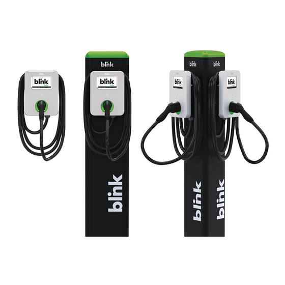
Charge on. Blink IQ 200 - Smart Model #: IQW2-80U-W1-N1-N-25 Figure 1-2. Smart Front View Blink IQ 200 - Kiosk Model #: IQW2-00U-M1-R2-N-00 Figure 1-3. Kiosk Front View... -
Page 9: Specifications
Charge on. 2 Specifications 2.1 Product Specifications Table 2-1. Product Specifications. Specification Item Kiosk Advanced (80A) Smart Advanced (32A) Input Rating 120/208/240 V~, 208/240 V~, single phase, 60 Hz. single phase, 60 0.22 A maximum. 80 A maximum. 32 A maximum. Power Input Connections Uncorded, Hard-Wired, L1, L2, and GND. - Page 10 Charge on. Specification Item Kiosk Advanced (80A) Smart Advanced (32A) None. LED Status Indicator: Charger Steady Green = Power On/Ready To Charge. Status Flashing Green (Fast) = Vehicle Connected/Ready To Charge. Indicators - Flashing Blue (Slow) = Charging. LDE Status Flashing Red = Warning/Fault.
- Page 11 Charge on. Specification Item Kiosk Advanced (80A) Smart Advanced (32A) Certificate Charging None. SAE J1772 compliant charging plug. Interface Instruction Manual x 1. Instruction Manual x 1. Quick Start Guide x 1. Quick Start Guide x 1. Limited Warranty x 1. Limited Warranty x 1.
-
Page 12: Installation
CHARGER. FAILURE TO DO SO MAY CAUSE PHYSICAL INJURY OR DAMAGE TO THE ELECTRICAL SYSTEM AND BLINK CHARGING UNIT. The Blink Charger should be installed only by a licensed contractor, and/or a licensed electrician in accor- dance with all applicable state, local and national electrical codes and standards. -
Page 13: Install The Charger
Charge on. 3.3 Install the Charger 1. Drill bolt holes in the wall for the mounting bracket. Note: Follow applicable accessibility requirements for the mounting position. The unit shall be mounted at a sufficient height from ground such that the height of the storage means for the coupling device is located between 24 inches (600 mm) and 4 feet (1.2 m) from ground per NEC Article 625. -
Page 14: Figure 3-2. Prepare For Wiring
Charge on. Figure 3-2. Prepare for Wiring. 3. Connect the electrical wiring to the Blink Charger. 3-1. Choose the appropriate conduit in accordance with all applicable state, local and national electrical codes and standards. -
Page 15: Figure 3-3. Terminal Tube
Charge on. Figure 3-3. Terminal tube. Clamp the Terminal, Terminal tube and Copper wire (Red is for L1, Black is for L2) 3-2. Figure 3-4. Remove the cover. Remove the plug cover (A or B) and use slotted screwdriver (if required) 3-3. -
Page 16: Figure 3-5. Wiring
Charge on. Figure 3-5. Wiring 3-4. Please use following wire and torque force when connecting to input terminal block. using conductor type other than RHH, RHW and RHW-2 with outer covering. Model Terminal Conductor Screw Rating Torque - lb-in (N-m) IQW2-80U-M1-R2-N-25 (Ad- L1, L2 2 AWG... -
Page 17: Figure 3-6. Blink Charger And Mounting Bracket
Charge on. Figure 3-6. Blink Charger and Mounting Bracket Align the screw holes of the mounting bracket with the Blink charger holes.(Use a torque force of 1.5 newton metre.) Figure 3-7. Mounting Bracket Screws. 5. Install and secure with four screws to the mounting bracket. (Use a torque force of 1.5 newton metre) -
Page 18: Figure 3-8. Blink Charger And Charger Plug
Charge on. Figure 3-8. Blink Charger and Charger Plug. -
Page 19: Web Portal Login Instructions
4.1.1 Setting Up the Local Network Firstly, connect a computer to the charge point using an Ethernet cable. There is an Ethernet RJ-45 port in the Blink Charger for connecting. Figure 4-1. Ethernet RJ-45 Port location. Secondly, set up a Static IP Address on your computer (except 169.254.63.255, cause it’s the default IP of Blink Charger. - Page 20 Charge on. 4.1.2 Log In Open a web browser (Internet Explorer for example) and enter the default IP of Blink Charger (169.254.63.255) in the address field of the browser and press enter. http://169.254.63.255/ Now you should see the login screen: To be able to configure the charge point you should enter “admin”...
-
Page 21: Web
Charge on. 4.2 Web-page Overview 4.2.1 Menu Overview There are five menu items available on the Web-page: Configuration, Maintenance, LLM Status, and Security. 4.2.2 Configuration Menu When you choose the Configuration menu, a sub menu will appear: The “Factory Settings” tab is used to display the information of the charge point. - Page 22 Charge on. 4.2.3 Maintenance Menu When you choose the Maintenance menu, a sub menu will appear: The “Command” screen can be used to restart the charge point and reset settings to MFG default. The “Firmware Upgrade” can be used to upgrade the firmware of the charge screen point.
- Page 23 Charge on. 4.2.5 Security Menu When you choose the Security menu, a sub menu will appear: The “Change Password” can be used to change the default screen password. 4.2.6 Operation Hours Menu When you choose the Operation Hours menu, a sub menu will appear.
- Page 24 Charge on. 4.2.7 Default Price Menu When you choose the Default Price menu, a sub menu will appear. The “Default shows the Default Parking Price. Default Parking Price could be Parking Price” modified here or recovery to default setting. screen The “Default shows the Default Usage Price.
-
Page 25: Configuration
Charge on. 4.3 Configuration 4.3.1 Factory Settings Clicking on the “Configuration” and then “Factory Settings” link will bring up the following screen: Charge Point Vendor The name of the charge point vendor. Charge Point Model The model of the charge point. Charge Point Serial The unique serial number of the charge point. - Page 26 Charge on. 4.3.2 Commissioning Settings Clicking on the “Configuration” and then “Commissioning Settings” link will bring up thefollowing screen: On this page you can change the properties of lQ-200. Click the “Apply” button when the value is changed. Charge Point ID The identity of the charger as known in the OCPP Central System.
- Page 27 Charge on. ICCID The ICCID of the modem’s SIM card. IMSI The IMSI of the modem’s SIM card. IMEI IMEI code for UMTS mobile system. e.g. 356938035643809. MEID MEID code for CDMA mobile system. e.g. A0123456789012. The Mobile Network Code of cellular service provider. Mobile Signal Strength Signal strength of mobile network.
- Page 28 Charge on. Max Amperage FW Setting Max Amperage allow base on FW design. Cold Load Pickup Max Default cold load pickup delay is 120s ~ 720s. Delay The max value could be changeable (between 120 ~ 720) by this property. EV Connect Timeout Interval (from successful authorization) until incipient charging session is automatically cancelled due to failure of EV user to (correctly) insert...
- Page 29 Charge on. Dim Option Indicate the timing to turn off LCD backlight. Valid options are: 1) Never (default). 2) 1 (minutes). 3) 2 (minutes). 4) 3 (minutes). 5) 4 (minutes). 6) 5 (minutes). 7) 10 (minutes). Dim Intensity The percentage of the backlight when DimOption is enabled. Unit in %. UMTS Dialnumber Dial-in number to access UMTS mobile network (e.g.
- Page 30 If true, Charge Point will support reservation related messages from Central System. Member Price Scheme ID The default price scheme ID will be used for Blink members when a Charge Point is offline. Non Member Price Scheme ID The default price scheme ID will be used for NON Blink members...
- Page 31 Charge on. 4.3.4 IP Settings Clicking on the “Configuration” and then “IP Settings” link will bring up the following screen: On this page you can set up the network connection. To finish, click the “Apply” button. Operation Mode Specifies if enable the Local Proxy function. Available options are Standalone, Primary and Secondary.
- Page 32 Charge on. Max Device Num- The maximum number of charge points allowed in a group/LAN. This value cannot be modified by users. Connectivity Specifies whether the charge point should always be connected to Internet using Auto, Ethernet, or 3G. Default value is Auto. Ping URL Address of the host that the charge point will ping for the Ethernet connection.
- Page 33 Charge on. 4.3.4.2 Wi-Fi Settings SSID SSID name to access Wi-Fi network (WAN). Security Security methods to access Wi-Fi network (WAN). Possible options are: 1) NONE 2) WPA_PERSONAL 3) WPA_ENTERPRISE 4) WPA2_PERSONAL 5) WPA2_ENTERPRISE 6) WEP 7) IEEE8021X 8) WPA2_PERSONAL_SHA256 9) WPA2_ENTERPRISE_SHA256 Mandatory for the following security: IEEE8021X.
- Page 34 Charge on. 4.3.4.3 Cellular Settings APN Name This is the gateway for all 3G traffic. Contact your 3G operator for information about this. APN User This is the user name your ISP has assigned to you (optional). APN Password Password to log into the ISP network (optional). Dial Number Phone number to dial.
-
Page 35: Maintenance
Charge on. 4.4 Maintenance 4.4.1 Command To restart the charge point, click the “Reboot” button. To reset the MFG default, click the “Reset to MFG default” button. 4.4.2 Firmware Upgrade To upgrade the firmware of the charge point, you need to download the upgrade image file to your local hard disk, and then click the “Choose File”... -
Page 36: Llm Status
Charge on. 4.5 LLM Status 4.5.1 LLM Information This page shows the Local Load Management information of the charge point. Device Operation Indicates the charger is in Standalone mode, a Primary or a Mode Secondary. LLM Mode Indicates LLM function is enabled or disabled. Network Status Indicates if the charger is online or not. -
Page 37: Security
Charge on. 4.6 Security 4.6.1 Change Password To change password, first choose user you want to change password. There are two default users – admin and maintain. Only admin user can access Security Page. Enter old password and new password then press “Apply” button to change password of the user. -
Page 38: Operation Hours
Charge on. 4.7 Operaon Hours 4.7.1 Operation Hours The “Operation Hours” screen shows the Operation Hour Setting of the whole Weekly. Operation Hour could be modified here or recovery to default setting. -
Page 39: Default Price
Charge on. 4.8 Default Price 4.8.1 Default Parking Price Interval Rate The base rate of EVSE to be applied for current pricing rule schedule entry. Parking Rate Billing Type Billing type, e.g. per time, per session or per kWh. Parking Schedule Day of Week Indicate the Day O fWeek. - Page 40 Charge on. 4.8.2 Default Usage Price Usage Rate Billing Type Billing type, e.g. per time, per session or per kWh. Usage Schedule Day of Week Indicate the Day O fWeek. Monday Based on ISO8601, Monday is the first day of week. Tuesday Based on ISO8601, Tuesday is the second day of week.
-
Page 41: Oqc Test
Charge on. 4.9 OQC Test 4.9.1 Test Function This page shows some functions for internal or quality department testing use. We recommend that users do not try to use any of the functions here. -
Page 42: Operations
Charge on. 5 Operations 5.1 About the Charger 5.1.1 Charging Status Indicators Table 5-1. Charging Status Indicators. Charger Plug DESCRIPTION DEFINITION LED Indicator Not illuminated Charger is powered OFF. Charger is powered ON / Ready for charging Steady Green / Charge Complete. Flashing gGeen Flashing green (Fast) = Vehicle Connected / Ready for charging. -
Page 43: Charging An Electric Vehicle (Ev)
Charge on. 5.2 Charging an Electric Vehicle (EV) 1. Release the charging plug from the charger holster and connect it to the EV. Figure 5-1. Remove the Charging Plug from the Charger Holster. Figure 5-2. Connect the Charging Plug to the EV. 2. -
Page 44: Figure 5-3. Blink Charger Screen
Charge on. 3. Go to Blink Charger, and to follow the instruction shown on the screen Figure 5-3. Blink Charger screen. - Page 45 Charge on. 1. START CHARGING 2. SWIPE CARD Touch anywhere of the screen to begin. 3. WAITING FOR 4. ENTER VEHICLE AUTHORIZING MILEAGE...
- Page 46 Charge on. 6. CHARGE 5. DOUBLE CONFIRM THE CONFIRMATION MILEAGE Press “CONTINUE” to the next page. 7. CHARGING SESSION STARTED...
-
Page 47: Stop Charging
Charge on. 5.3 Stop Charging 2. READ COST 1. UNPLUG ANY TIME SUMMARY Disconnect the charging plug Read the cost summary and from EV to stop charging then press “CLOSE”. session. 4. GO BACK TO THE 3. SESSION ENDED MAIN SCREEN Please return the connector to the holster and touch anywhere of the screen. -
Page 48: Figure 5-4. Place The Charging Plug Into The Charger Holster
• For Over Current conditions: The charging seesion will be stop while OC occurs. After recovery from OC for 30 seconds, Blink Charger will automatically restart charging for three times. • When charging session stopped due to CCID trip, Blink Charger will try to restart after 15 minutes for 3 times. -
Page 49: Troubleshooting
Table 5-2. Troubleshooting Description. SITUATION Screen Displayed ACTION 1. Station Disabled. Out Of Service (Sta- 2. Please call 1-888-998-BLINK (2546) tion Disable) for assistnce. 1. Internal Maintenance. Out Of Service (Inter- 2. Please call 1-888-998-BLINK (2546) nal Maintenance) for assistnce. - Page 50 Payment Card De- clined 2. For assistance, please call 1-888-998-BLINK (2546). 1. This code has expired. Blink Codes are only valid for 24 hours. Blink Code is not 2. To purchase another Blink Code visit www.blinkcode.com.
- Page 51 Charge on. SITUATION Screen Displayed ACTION 1. Please reconfirm your Unit # and retry. The Selected Blink Unit 2. For assistance, please call is an invalid Unit. 1-888-998-BLINK (2546). 1. Please try to a different chargeing The Selected Blink Unit station.
-
Page 52: General Care
• Ensure the power cable is stored on the charger after use to avoid damage. • If the power cable or the charging plug is damaged contact Customer Support. 5.6 Customer Support If the Charger is not operational or you need our assistance, please call: 1-888-998-BLINK (2546).
Need help?
Do you have a question about the IQ 200 and is the answer not in the manual?
Questions and answers