
Subscribe to Our Youtube Channel
Related Manuals for Vision Fitness U60


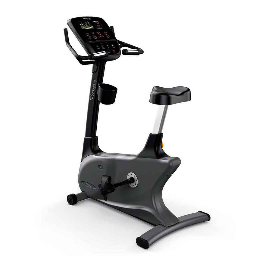
Summary of Contents for Vision Fitness U60
- Page 1 IT ALL STARTS WITH A VISION IT ALL STARTS WITH A VISION FITNESS™ U 6 0 B I K E S E R V I C E M A N U A L...
-
Page 2: Table Of Contents
TABLE OF CONTENTS CHAPTER 1: SERIAL NUMBER LOCATION ..............CHAPTER 2: IMPORTANT SAFETY INSTRUCTIONS Before Getting Started ....................2 Read and Save These Instructions ................3 Electrical Requirements .................... 4 CHAPTER 3: PREVENTATIVE MAINTENANCE Recommended Cleaning Tips ................... 5 Check for Damaged Parts ..................5 Care and Maintenance Instructions ................ - Page 3 TABLE OF CONTENTS CHAPTER 8: BIKE SPECIFICATIONS AND ASSEMBLY GUIDE Unpacking the Bike ....................47 Assembly Tools ......................48 Assembly Instructions ....................49 Adjusting the Pedal Straps and Seat ................. 55 Leveling the Bike ......................56 CHAPTER 9: SOFTWARE UPGRADE GUIDE Software Upgrade Instructions ...................
-
Page 4: Chapter 1: Serial Number Location
CHAPTER 1: SERIAL NUMBER LOCATION 1.1 SERIAL NUMBER LOCATION... -
Page 5: Chapter 2: Important Safety Instructions
Please do not place the Vision Fitness U60 Bike in an area of high humidity, such as the vicinity of a steam room, indoor pool, or sauna. Exposure to intensive water vapor or chlorine could adversely affect the electronics, as well as other parts of the machine. -
Page 6: Read And Save These Instructions
To ensure proper use of the Vision Fitness U60 Bike, make sure that all users read this manual. Remind the users that before CAUTION! Any changes or modifications to this equipment undertaking any fitness program, they should obtain complete could void the product warranty. -
Page 7: Electrical Requirements
SELF POWERED FEATURES: The Vision Fitness U60 Bike is a self-powered unit, requiring no external power source. When a user pedals at a speed above 20 revolutions per minute, the power is generated to allow the bike to function properly. Because of this self-generating feature, the console feedback will fade away when you cease pedaling. -
Page 8: Chapter 3: Preventative Maintenance
MAINTAIN LABELS AND NAMEPLATES. Do not remove labels • P osition the equipment away from direct sunlight. The intense UV light for any reason. They contain important information. If unreadable can cause discoloration on plastics. or missing, contact Vision Fitness for a replacement at 800-335- 4348 or www.visionfitness.com. • L ocate your equipment in an area with cool temperatures and low humidity. -
Page 9: Care And Maintenance Instructions
3.3 CARE AND MAINTENANCE INSTRUCTIONS In order to maximize life span, and minimize down time, all Vision Fitness equipment requires regular cleaning, and maintenance items performed on a scheduled basis. This section contains detailed instructions on how to perform these items and the frequency of which they should be done. -
Page 10: Chapter 4: Console Overlay And Workout Description
CHAPTER 4: CONSOLE OVERLAY AND WORKOUT DESCRIPTION 4.1 CONSOLE DESCRIPTION A. Go / Enter / Hold to Scan - Press the GO key to begin a Manual workout immediately without setting individual information. All feedback information will be calculated using default settings. ENTER - This key is used to approve each piece of information used during setup. HOLD TO SCAN - If you need to change the display view, you can do so by holding down this key for 3 seconds. - Page 11 CHAPTER 4: CONSOLE OVERLAY AND WORKOUT DESCRIPTION 4.1 CONSOLE DESCRIPTION - CONTINUED CARDIO PORT A cardio port is located on the back of the console that is compatible to entertainment protocol such as Cardio Theater. The bottom port is the active port to use for this function.
-
Page 12: Workout Overview
CHAPTER 4: CONSOLE OVERLAY AND WORKOUT DESCRIPTION 4.2 WORKOUT OVERVIEW WORKOUT OVERVIEW CLASSICS: MANUAL - Manual is a user controlled program in which the resistance remains as set level unless you decide to change it. INTERVAL - Interval is an efficient workout that strengthens your cardiovascular system by alternating work intervals and recovery intervals. Be sure to challenge yourself with intense work intervals. -
Page 13: Using The Programs
CHAPTER 4: CONSOLE OVERLAY AND WORKOUT DESCRIPTION 4.3 USING THE PROGRAMS USING THE PROGRAMS SELECTING QUICK START - The easiest way to begin exercising is to simply press the GO key (Figure A). You will begin exercising in a Manual resistance program in which you can change the resistance levels to meet your goals. Current default settings will be used to determine exercise feedback. - Page 14 CHAPTER 4: CONSOLE OVERLAY AND WORKOUT DESCRIPTION 4.3 USING THE PROGRAMS - CONTINUED USING THE PROGRAMS - Continued ENTERING RESISTANCE - When prompted by the message center to enter level, use the UP and DOWN ARROW keys to adjust the displayed resistance level (Figure E).
-
Page 15: Chapter 5: Manager Mode
CHAPTER 5: MANAGER MODE 5.1 USING MANAGER MODE The Manager Mode allows the owner to customize the bike. 1) To enter Manager Mode, press and hold down the UP and DOWN RESISTANCE keys at the same time for 3-5 seconds (Figure A). 2) The display will read P1 Max Time (Figure B). - Page 16 CHAPTER 5: MANAGER MODE 5.1 USING MANAGER MODE - CONTINUED CUSTOM SETTINGS DEFAULT MINIMUM MAXIMUM DESCRIPTION MAX TIME Maximum workout duration. USER TIME 99 (LIMITED Default start time in all programs. TO MAX TIME SETTING) DEFAULT AGE Default age used for all programs. RESISTANCE LEVEL Default resistance used for all programs.
-
Page 17: Chapter 6: Troubleshooting
CHAPTER 6: TROUBLESHOOTING 6.1 ELECTRICAL DIAGRAMS... - Page 18 CHAPTER 6: TROUBLESHOOTING 6.1 ELECTRICAL DIAGRAMS...
- Page 19 CHAPTER 6: TROUBLESHOOTING 6.1 ELECTRICAL DIAGRAMS P01 - CONSOLE CABLE...
-
Page 20: Lcb Wiring Instructions
CHAPTER 6: TROUBLESHOOTING 6.2 LCB WIRING INSTRUCTIONS LCB WIRING INSTRUCTIONS J2 - 7 pin terminal to the console. J3 - 3 pin terminal to the generator. J4 - 2 pin terminal to the power resistor. -
Page 21: Ucb Wiring Instructions
CHAPTER 6: TROUBLESHOOTING 6.3 UCB WIRING INSTRUCTIONS LCB WIRING INSTRUCTIONS J5 - Console cable wire. J6 - Heart rate board (grips) wire. J7 - Heart rate board (wireless). J8 - Battery Wire. J9 - Hand Grip 2 J10 - Heart rate board (grips). J11 - Hand Grip 1... -
Page 22: Troubleshooting - Keypad Issues
CHAPTER 6: TROUBLESHOOTING 6.4 TROUBLESHOOTING - CONSOLE POWER ISSUES NO DISPLAY ON THE CONSOLE OR THE DISPLAY IS DIM POSSIBLE CAUSES: 1) The console is damaged or the console cable is not connected properly. 2) Poor connection to the terminals on the lower control board. 3) The lower control board is damaged. -
Page 23: Troubleshooting - No Rpm Displayed
CHAPTER 6: TROUBLESHOOTING 6.5 TROUBLESHOOTING - NO RPM DISPLAYED NO RPM IS DISPLAYED DURING EXERCISE POSSIBLE CAUSES: 1) The console is damaged. 2) The console cable is not connected to the console or LCB or damaged. 3) The lower control board is damaged. 4) The generator is damaged. -
Page 24: Troubleshooting - Noise Issues
CHAPTER 6: TROUBLESHOOTING 6.6 TROUBLESHOOTING - KEYPAD ISSUES ALL OR SOME OF THE FUNCTION KEYS DO NOT RESPOND POSSIBLE CAUSES: 1) The keypad ribbon cable is not connected correctly. 2) The keypad is damaged. 3) The console is damaged. SOLUTION 1) Check of the connection of the keypad ribbon cable at the UCB (procedure below). -
Page 25: Troubleshooting - No Or High Resistance
CHAPTER 6: TROUBLESHOOTING 6.7 TROUBLESHOOTING - HIGH OR NO RESISTANCE HIGH OR NO RESISTANCE POSSIBLE CAUSES: 1) The console is damaged. 2) The console cable is not connected to the console or LCB or damaged. 3) The power resistor is damaged. 4) The lower control board is damaged. -
Page 26: Troubleshooting - Pedals Slipping
CHAPTER 6: TROUBLESHOOTING 6.8 TROUBLESHOOTING - PEDALS SLIPPING SLIPPING WHILE PEDALING POSSIBLE CAUSES 1) Check to make sure that the tension pulley pivots freely. 2) Belt tension is not enough. 3) The one way bearing in the secondary pulley axle is damaged. SOLUTION: 1) Clean and lubricate the tension pulley as needed. -
Page 27: Troubleshooting - Heart Rate Issues
CHAPTER 6: TROUBLESHOOTING 6.10 TROUBLESHOOTING - HEART RATE ISSUES HEART RATE DOES NOT WORK POSSIBLE CAUSES: 1) Not good contact between the user and HR grips or HR strap. 2) The HR strap is at a low battery status. 3) The HR strap is damaged. 4) The HR grips are damaged. -
Page 28: Chapter 7: Part Replacement Guide
CHAPTER 7: PART REPLACEMENT GUIDE 7.1 CONSOLE REPLACEMENT 1) Remove the 4 screws holding the console to the console mast (Figure A). FIGURE A 2) Disconnect the console cable and HR connections from the defective console and remove it (Figure B). FIGURE B 3) Connect the wire connections to the new console. -
Page 29: Heart Rate Handlebar Replacement
CHAPTER 7: PART REPLACEMENT GUIDE 7.2 HEART RATE HANDLEBAR REPLACEMENT 1) Remove the 4 screws holding the heart rate handlebar to the console mast being careful to support the handlebar (Figure A). FIGURE A 2) Carefully pull the three wires out of the console mast until the connectors are showing, and then disconnect the two wires and remove the defective heart rate handlebar (Figure B). -
Page 30: Heart Rate Grips Replacement
CHAPTER 7: PART REPLACEMENT GUIDE 7.3 HEART RATE GRIP REPLACEMENT 1) Remove the 2 screws holding the 2 halves of the heart rate grip together (Figure A). 2) Once the 2 screws are removed, pull apart the top and bottom portions of the heart rate grip (Figure B). FIGURE A FIGURE B 3) Disconnect the heart rate plate wiring and remove the old HR grip (Figure C). -
Page 31: Accessory Tray Replacement
CHAPTER 7: PART REPLACEMENT GUIDE 7.4 ACCESSORY TRAY REPLACEMENT 1) Remove the 2 screws holding Accessory Tray to the console mast (Figure A). FIGURE A 2) Remove the Accessory Tray (Figure B). FIGURE B 3) Reverse Steps 1-2 to install a new Accessory Tray. -
Page 32: Console Mast Replacement
CHAPTER 7: PART REPLACEMENT GUIDE 7.5 CONSOLE MAST REPLACEMENT 1) Remove the console as outlined in Section 7.1. 2) Remove the heart rate handlebar as outlined in Section 7.2. 3) Lift up the console mast boot (Figure A). 4) Remove the 5 screws holding the console mast to the frame (Figure B). FIGURE A FIGURE B 5) Pull the wires out of the bottom of the console mast and remove the mast (Figure C). -
Page 33: Seat Pad Replacement
CHAPTER 7: PART REPLACEMENT GUIDE 7.6 SEAT PAD REPLACEMENT 1) Remove the three screws holding the seat pad to the seat post (Figure A). FIGURE A 2) Remove the seat pad from the seat post (Figure B). FIGURE B 3) Reverse Steps 1-2 to install a new seat pad. -
Page 34: Seat Post Replacement
CHAPTER 7: PART REPLACEMENT GUIDE 7.7 SEAT POST REPLACEMENT 1) Remove the seat adjustment pin (Figure A). 2) Pull the seat post upward until the stem comes away from the frame and remove it (Figure B). FIGURE A FIGURE B 3) Remove the rubber boot at the bottom of the seat post (Figure C). -
Page 35: Seat Post Insert Replacement
CHAPTER 7: PART REPLACEMENT GUIDE 7.8 SEAT POST INSERT REPLACEMENT 1) Remove the seat adjustment pin (Figure A). 2) Pull the seat post upward until the stem comes away from the frame and remove it (Figure B). FIGURE A FIGURE B 3) Remove the rubber boot at the bottom of the seat post (Figure C). -
Page 36: Pedal Replacement
CHAPTER 7: PART REPLACEMENT GUIDE 7.9 PEDAL REPLACEMENT 1) Use a 15mm pedal wrench to remove the pedal from the axle (Figure A). NOTE: The threads on the left side pedal are reversed (the pedal turns off counter clockwise). FIGURE A 2) Remove the pedal (Figure B). -
Page 37: Crank Replacement
CHAPTER 7: PART REPLACEMENT GUIDE 7.10 CRANK REPLACEMENT NOTE: A Matrix special tool is required to properly replace a crank. Order part # 022696-00 from Matrix Customer Technical Support. 1) Assemble the Matrix tool as shown in Figure A. Note that there are 2 different sides on the tool. 2) Remove the crank arm cover by turning it counter clockwise (Figure B). -
Page 38: Side Cover Replacement
CHAPTER 7: PART REPLACEMENT GUIDE 7.11 SIDE COVER REPLACEMENT 1) Remove the seat adjustment pin (Figure A). 2) Pull the seat post upward until the stem comes away from the frame and remove it (Figure B). 3) Remove the rubber boot at the bottom of the seat post (Figure C). FIGURE A FIGURE B FIGURE C... -
Page 39: Lower Control Board Replacement
CHAPTER 7: PART REPLACEMENT GUIDE 7.12 LOWER CONTROL BOARD REPLACEMENT 1) Remove the side covers as outlined in Section 7.11. . 2) Disconnect the 3 wires that are plugged into the lower control board (Figure A). 3) Remove the 2 screws holding the lower control board to the frame (Figure B). FIGURE A FIGURE B 4) Reverse Steps 1-3 to install a new lower control board. -
Page 40: Drive Belt Replacement
CHAPTER 7: PART REPLACEMENT GUIDE 7.13 DRIVE BELT REPLACEMENT 1) Remove the right front side cover as outlined in Section 7.11. 2) Pull up on the tension assembly and walk the belt off of the idler pulley (Figure A). 3) Remove the drive belt (Figure B). FIGURE A FIGURE B 4) Reverse Steps 1-3 to install a new drive belt. -
Page 41: Tension Assembly Replacement
CHAPTER 7: PART REPLACEMENT GUIDE 7.14 TENSION ASSEMBLY REPLACEMENT 1) Remove the front side covers as outlined in Section 7.11. 2) The tension assembly is held to the frame by one bolt and nut (Figures A & B). FIGURE A FIGURE B 3) Remove the tension assembly spring (Figure C). -
Page 42: Generator Belt Replacement
CHAPTER 7: PART REPLACEMENT GUIDE 7.15 GENERATOR BELT REPLACEMENT 1) Remove both front side covers as outlined in Section 7.11. 2) Remove the cable ties holding the generator cable to the frame (Figure A). 3) Remove the nut on each side of the frame holding the generator in place (Figure B). FIGURE A FIGURE B 4) Remove the nut on each side putting tension on the generator belt (Figure C). -
Page 43: Generator Replacement
CHAPTER 7: PART REPLACEMENT GUIDE 7.16 GENERATOR REPLACEMENT 1) Remove both front side covers as outlined in Section 7.11. 2) Remove the cable ties holding the generator cable to the frame (Figure A). 3) Remove the nut on each side of the frame holding the generator in place (Figure B). FIGURE A FIGURE B 4) Remove the nut on each side putting tension on the generator belt (Figure C). -
Page 44: Drive Axle Set Replacement
CHAPTER 7: PART REPLACEMENT GUIDE 7.17 DRIVE AXLE SET REPLACEMENT 1) Remove both front side covers as outlined in Section 7.11. 2) Pull up on the tension assembly and remove the drive belt as outlined in Section 7.13. 3) Remove the snap ring on the left side of the unit holding the drive axle bearing into the frame (Figures A & B). FIGURE A FIGURE B 4) Use a hammer to hit the drive axle shaft until it is loose in the frame, then remove it (Figures C &... - Page 45 CHAPTER 7: PART REPLACEMENT GUIDE 7.17 DRIVE AXLE SET REPLACEMENT - CONTINUED 5) Use a hammer and punch to hit the remaining bearing until it is loose in the frame, then remove it (Figures F & G). NOTE: The bearing cannot be re-used after being removed.
-
Page 46: Secondary (Pulley) Axle Set Replacement
CHAPTER 7: PART REPLACEMENT GUIDE 7.18 SECONDARY (PULLEY) AXLE SET REPLACEMENT 1) Remove both front side covers as outlined in Section 7.16. 2) Remove the tension assembly spring (Figure A). 3) Pull up on the tension assembly and remove the drive belt (Figure B). FIGURE A FIGURE B 4) Walk the generator belt off of the secondary pulley (Figure C). - Page 47 CHAPTER 7: PART REPLACEMENT GUIDE 7.18 SECONDARY (PULLEY) AXLE SET REPLACEMENT - CONTINUED 6) Turn the secondary pulley until each of the 3 screws through the frame are exposed (Figures E - G). 7) Re-install the screw removed in Step 5 (the screw will protect the drive axle shaft - Figure H). FIGURE E FIGURE F FIGURE H...
-
Page 48: Rear Stabilizer Replacement
CHAPTER 7: PART REPLACEMENT GUIDE 7.19 REAR STABILIZER REPLACEMENT 1) Lean the bike to one side and remove the 4 screws holding the rear stabilizer to the frame (Figure A). FIGURE A 2) Remove the rear stabilizer (Figure B). FIGURE B 3) Reverse Steps 1-2 to install a new rear stabilizer. -
Page 49: Testing The Bike
CHAPTER 7: PART REPLACEMENT GUIDE 7.20 TESTING THE BIKE ONCE THE UNIT OR REPLACEMENT PART IS FULLY INSTALLED AND ASSEMBLED AND PROPERLY PLACED ON THE FLOOR, USE THE FOLLOWING INSTRUCTIONS TO TEST THE MACHINE: 1) Without hitting start or entering any program modes, sit on the bike and hold the handlebars while pedaling to simulate exercising. While moving, listen for any odd noises or squeaks. -
Page 50: Chapter 8: Bike Specifications And Assembly Guide
CHAPTER 8: BIKE SPECIFICATIONS AND ASSEMBLY GUIDE 8.1 UNPACKING THE BIKE The Vision Fitness U60 Bike is carefully inspected before shipment, so it should arrive in good operating condition. Vision Fitness ships the bike in the following pieces: NOTE : If these parts are missing from the package, please contact Vision Fitness at 1-800-335-4348. -
Page 51: Assembly Tools
CHAPTER 8: BIKE SPECIFICATIONS AND ASSEMBLY GUIDE 8.2 ASSEMBLY TOOLS TOOLS REQUIRED FOR ASSEMBLY 6mm Allen Wrench 5mm Allen Wrench 4mm Allen Wrench... -
Page 52: Assembly Instructions
CHAPTER 8: BIKE SPECIFICATIONS AND ASSEMBLY GUIDE 8.3 ASSEMBLY INSTRUCTIONS STEP 1 - ORANGE BAG 1) Install the rear foot with four lock washers (M8), two inside bolts (M8 x 65L), and two outside bolts (M8 x 20L). Tighten with the 5mm L-Shaped Allen Wrench. - Page 53 CHAPTER 8: BIKE SPECIFICATIONS AND ASSEMBLY GUIDE 8.3 ASSEMBLY INSTRUCTIONS - CONTINUED STEP 2 - BLUE BAG 1) Put the wire through the console mast, then use five bolts (M8 x 16L) and lock washers (M8) to fix the console mast onto the frame bracket with the 6mm L-Shaped Wrench.
- Page 54 CHAPTER 8: BIKE SPECIFICATIONS AND ASSEMBLY GUIDE 8.3 ASSEMBLY INSTRUCTIONS - CONTINUED STEP 3 - PINK BAG 1) Feed the heart rate wires of the handlebar through the small hole located in the front of the console mast. Pull these wires up through the hole at the top of the console mast.
- Page 55 CHAPTER 8: BIKE SPECIFICATIONS AND ASSEMBLY GUIDE 8.3 ASSEMBLY INSTRUCTIONS - CONTINUED STEP 4 - YELLOW BAG 1) Remove the four mounting bolts from the back of the console and four screws holding the console back cover on with the Phillips Screwdriver.
- Page 56 CHAPTER 8: BIKE SPECIFICATIONS AND ASSEMBLY GUIDE 8.3 ASSEMBLY INSTRUCTIONS - CONTINUED STEP 5 - PEDAL 1) Attach the pedals to the crank and tighten them using the 15mm Pedal Wrench. Tighten the pedal as tight as possible (it is impossible to over-tighten the pedal).
- Page 57 CHAPTER 8: BIKE SPECIFICATIONS AND ASSEMBLY GUIDE 8.3 ASSEMBLY INSTRUCTIONS - CONTINUED FINAL ASSEMBLY...
-
Page 58: Adjusting The Pedal Straps And Seat
Release the clip to lock the strap in place. ADJUSTING THE U60 SEAT The U60 bike uses a simple pull pin adjustment knob to adjust the seat height. To adjust the seat, grab hold of the seat and pull the seat post knob out. -
Page 59: Leveling The Bike
CHAPTER 8: BIKE SPECIFICATIONS AND ASSEMBLY GUIDE 8.5 LEVELING THE BIKE STABILIZING THE VISION FITNESS U60 BIKE After positioning the bike in its intended location, check its stability by attempting to shake it side to side. Shaking or wobbling indicates that your bike needs to be leveled. -
Page 60: Chapter 9: Software Upgrade Guide
CHAPTER 9: SOFTWARE UPGRADE GUIDE 9.1 SOFTWARE UPGRADE INSTRUCTIONS PARTS NEEDED: 1. MSP-FET430 Gang Programmer 2. Part # MTOOL-039 3. Software A: 14 Pin B: Power Supply Specification 8-15V 300MA MSP-FET430 TOOLS 1) Connect the MSP-GANG430 hardware, PC, and console as shown in Figure A. FIGURE A... - Page 61 CHAPTER 9: SOFTWARE UPGRADE GUIDE 9.1 SOFTWARE UPGRADE INSTRUCTIONS - CONTINUED 2) Click on the GANG430 icon located in the program group specified during installation of the software (the default group is ADT430). The MSP430 FLASH Gang Programmer GUI is shown in Figure B as displayed on the screen. FIGURE B The status message in the GUI displays the message "MSP-GAMG430 Gang Processor connected."...
- Page 62 CHAPTER 9: SOFTWARE UPGRADE GUIDE 9.1 SOFTWARE UPGRADE INSTRUCTIONS - CONTINUED 4) After the first console installation is finished, you can remove the RS232 cable from the PC to MSP-GANG430 as shown in Figure D. Upgrade the other consoles using MSP-GANG430 as shown in Figure E. Press the MSP430 Start button, the "MODE" LED will glitter for about 10 seconds.
- Page 63 NOTES...
- Page 64 IT ALL STARTS WITH A VISION™ V IS ION F ITN ES S SY S TE MS C OR P. 16 10 L A N D MA R K D RIV E C O TTA GE GR O V E W I 5 352 7 U S A w w w.
Need help?
Do you have a question about the U60 and is the answer not in the manual?
Questions and answers