Topcon GR-3 Operator's Manual
Hide thumbs
Also See for GR-3:
- Operator's manual (28 pages) ,
- Operator's manual (26 pages) ,
- Operator's manual (196 pages)
Table of Contents
Advertisement
Quick Links
Advertisement
Table of Contents
Troubleshooting

Related Manuals for Topcon GR-3


Summary of Contents for Topcon GR-3
- Page 3 Rev A ©Copyright Topcon Positioning Systems, Inc. June, 2006 All contents in this manual are copyrighted by Topcon. All rights reserved. The information contained herein may not be used, accessed, copied, stored, displayed, sold, modified, published, or distributed, or otherwise reproduced without express written consent from Topcon.
- Page 4 ECO#2808...
-
Page 5: Table Of Contents
Essential Components for Quality Surveying ..1-5 Conclusion ............1-6 Receiver Overview ............ 1-6 Getting Acquainted ............1-8 Batteries ..............1-8 GR-3 Receiver ............1-10 MINTER ............. 1-11 Data and Power Ports ......... 1-16 External Radio Antenna Connector ....1-17 Connector ............1-17 SD/MMC and SIM Card Slots ...... - Page 6 Configuring a GSM Radio Modem ......3-7 Configuring the Receiver ..........3-10 MINTER Configuration ........... 3-20 Chapter 4 GR-3 Receiver Setup and Survey ....... 4-1 Receiver Setup ..............4-1 Step 1: Set up the Receivers ........4-1 Step 2: Measure Antenna Height ....... 4-4 Step 3: Collect Data ...........
- Page 7 Table of Contents Chapter 5 Receiver and File Maintenance ......5-1 Downloading Files to a Computer ........5-1 Downloading Files via Topcon Link ......5-2 ...Using Windows Explorer ........ 5-2 ...Using Topcon Link .......... 5-4 Downloading Files via PC-CDU ....... 5-6 Deleting Files from the Receiver’s SD Card ....
- Page 8 General Warnings ............. B-1 Battery Pack Warnings ............. B-2 Usage Warnings ............... B-3 Appendix C Regulatory Information ........C-1 FCC Compliance .............. C-1 Community of Europe Compliance ........C-2 WEEE Directive ............... C-2 Appendix D Warranty Terms ........... D-1 Index GR-3 Operator’s Manual...
-
Page 9: Preface
Preface Preface Thank you for purchasing this Topcon product. The materials available in this Manual (the “Manual”) have been prepared by Topcon Positioning Systems, Inc. (“TPS”) for owners of Topcon products, and are designed to assist owners with the use of the receiver and its use is subject to these terms and conditions (the “Terms and Conditions”). - Page 10 Windows® is a registered trademark of Microsoft Corporation. The Bluetooth® word mark and logos are owned by Bluetooth SIG, Inc. and any use of such marks by Topcon Positioning Systems, Inc. is used under license. Other product and company names mentioned herein may be trademarks of their respective owners.
- Page 11 Terms and Conditions You may not assign or transfer the Software or this license without the express written consent of TPS. This license is effective until terminated. You may terminate the license at any time by destroying the Software and Manual. TPS may terminate the license if you fail to comply with any of the Terms or Conditions.
-
Page 12: Manual Conventions
Notification that an action has the potential to adversely affect system operation, system CAUTION performance, data integrity, or personal health. Notification that an action will result in system damage, loss of data, loss of warranty, or personal WARNING injury. GR-3 Operator’s Manual viii... - Page 13 Manual Conventions Under no circumstances should this action be DANGER performed. P/N 7010-0736...
- Page 14 Preface Notes: GR-3 Operator’s Manual...
-
Page 15: Chapter 1 Introduction
Chapter 1 Introduction The GR-3 receiver is a multi-frequency, GPS+ receiver built to be the most advanced and compact receiver for the surveying market. The receiver is a multi-function, multi-purpose receiver intended for precision markets. Precision markets means markets for equipment,... -
Page 16: Principles Of Operation
European space agencies/companies working closely with the European Space Agency. Unlike GPS and GLONASS, this is a civil endeavor and is currently in the development and validation stage. For information on the status of this system, visit the Galileo Industries website (http://www.galileo-industries.net). GR-3 Operator’s Manual... -
Page 17: Calculating Absolute Positions
Principles of Operation Despite numerous technical differences in the implementation of these systems, satellite positioning systems have three essential components: • Space – GPS, GLONASS, and GALILEO satellites orbit approximately 12,000 nautical miles above Earth and are equipped with a clock and radio. These satellites broadcast ranging signals and various digital information (ephemerides, almanacs, time&frequency corrections, etc.). -
Page 18: Calculating Differential Positions
(not sent over communication link). Later, the data are downloaded to computer, combined, and processed. Using this technique, the spatially correlated errors—such as satellite orbital errors, ionospheric errors, and tropospheric errors—can be significantly reduced, thus improving the position solution accuracy. GR-3 Operator’s Manual... -
Page 19: Essential Components For Quality Surveying
Principles of Operation A number of differential positioning implementations exist, including post-processing surveying, real-time kinematic surveying, maritime radio beacons, geostationary satellites (as with the OmniSTAR service), and satellite based augmentation systems (WAAS, EGNOS, MSAS). The real-time kinematic (RTK) method is the most precise method of real-time surveying. -
Page 20: Conclusion
Once the signal is locked in the channel, it is demodulated and necessary signal parameters (carrier and code phases) are measured. Also, broadcast navigation data are retrieved from the navigation frame. GR-3 Operator’s Manual... - Page 21 Principles of Operation After the receiver locks on to four or more satellites, its absolute position in WGS-84 and the time offset between the receiver clock and GPS time are computed. This information and the measurement data can be stored in the optional MMC or SD card and downloaded later onto a computer, then processed using a post-processing software package.
-
Page 22: Getting Acquainted
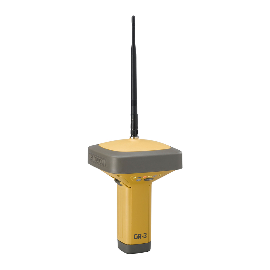
Introduction Getting Acquainted The GR-3 is a 72-channel GPS receiver with external, detachable batteries, two data ports, an interface for controlling and viewing data logging, external memory card slot, an internal radio modem, a Bluetooth® wireless technology module, and an optional GSM/GPRS module. - Page 23 Getting Acquainted fully charged in approximately six hours. The batteries should run at no less than 80% capacity after 500 charging cycles. These batteries do not need to be drained before recharging. The charger has two ports, one button, and three LEDs. •...
-
Page 24: Gr-3 Receiver
CAUTION modem is in transmitter mode. GR-3 Receiver The GR-3 receiver’s advanced design reduces the number of cable required for operation, allowing you to survey more reliably and efficiently. The casing allocates space for two removable, rechargeable batteries, SD/MMC and SIM card slots, a Bluetooth wireless technology module, a multi-system receiver board, and a radio modem communications board. -
Page 25: Minter
• Green blink – receiver is on and tracking satellites; one blink per tracked GPS satellite. • Orange blink – receiver is on and tracking satellites; one blink per tracked GLONASS satellite. RX TX STAT FUNCTION Battery Battery FUNCTION FUNCTION Power Button Button Figure 1-5. GR-3 MINTER P/N 7010-0736 1-11... - Page 26 Table 1-1 The RX TX LED describes the LED colors and patterns for the different modems available for the GR-3 receiver. Table 1-1. RX TX LED Indications • No light – modem is turned off.
- Page 27 Getting Acquainted Table 1-1. RX TX LED Indications (Continued) • Solid Orange (Red and Green) – the modem is initializing. • Green flashes – the modem is on, registered on the network, and is waiting for incoming calls (Slave mode). •...
- Page 28 If FUNCTION key mode is “Occupation mode switch” Green Release to start recording (Kinematic or Static post-processing occupation mode) Pressed for 5–8 Release to turn serial port A baud rate to seconds 9600 bps. Pressed for > 8 No light No function. seconds GR-3 Operator’s Manual 1-14...
- Page 29 Getting Acquainted Table 1-2. FUNCTION Button Operations and REC LED Status (Continued) FUNCTION Key REC LED Status When data recording is on, and the FUNCTION key is... No free memory; hardware problem with data recording. If FUNCTION key mode is “LED blink mode switch” Green Data recording started (post-processing occupation mode undefined).
-
Page 30: Data And Power Ports
Introduction Data and Power Ports The GR-3 has the following three ports (Figure 1-6): • USB – rimmed in yellow; used for high-speed data transfer and communication between the receiver and an external device. The body of the connector on the corresponding cable is yellow. -
Page 31: External Radio Antenna Connector
Getting Acquainted External Radio Antenna Connector The SS antenna connects to the external antenna connector on the GR-3 radome (Figure 1-7). The SS/GSM antenna uses a reverse polarity TNC connection. External Antenna Connector Figure 1-7. GR-3 Radome and External Antenna Connector... -
Page 32: Sd/Mmc And Sim Card Slots
SIM card installed can be accessed via Modem-TPS for configuration purposes. A SIM card can be purchased from your local cellular provider. Card Slot (for SD/MMC card) Figure 1-9. GR-3 Card Slot Example 1. MMC = multi-media card; SD = secure digital GR-3 Operator’s Manual 1-18... -
Page 33: Cables
Cables The GR-3 package includes standard communication and power cables for configuring the receiver and providing a power source to the receiver. Table 1-3 lists the cables included in the GR-3 package. Table 1-3. GR-3 Package Cables Cable Description Cable Illustration... -
Page 34: Other Accessories
Introduction Other Accessories Along with the following accessories, the GR-3 package includes a 128 MB SD memory card, 3-meter measuring tape, an adjustable range pole, and a cable bag. (p/n 22-034101-01) charges the internal The Power Supply unit batteries when connected to a grounded outlet (Figure 1-10). This... - Page 35 Using the side clips, the receiver can be quickly connected to/disconnected from the range pole (Figure 1-13). Figure 1-13. Quick Disconnect For more details on the accessories and package options available for the GR-3, contact your local Topcon dealer. P/N 7010-0736 1-21...
-
Page 36: Optional Accessories
Introduction Optional Accessories Topcon offers a wide variety of accessories especially designed to extend your job reliability and efficiency. For more details on the optional accessories available for the GR-3, contact your local Topcon dealer. (Figure 1-14) is used to precisely The precision tribrach adapter center, align, and level the tripod over a point. -
Page 37: Option Authorization File (Oaf)
(Figure 1-13). Figure 1-16. Auxiliary Power Cable – ODU-to-Alligator Clips Option Authorization File (OAF) Topcon Positioning Systems issues an Option Authorization File (OAF) to enable the specific options that customers purchase. An Option Authorization File allows customers to customize and configure the receiver according to particular needs, thus only purchasing those options needed. - Page 38 Introduction Notes: GR-3 Operator’s Manual 1-24...
-
Page 39: Pre-Survey Preparation
Chapter 2 Pre-survey Preparation Before beginning to survey with the GR-3 receiver, the following software needs to be installed and configurations need to be applied: Install receiver configuration software See “Installing Topcon Software” on page 2-2. Optional: install SD card and/or SIM card See “Installing the Optional SD and SIM Cards”... -
Page 40: Installing Topcon Software
The PC-CDU software exists in two versions: a full-functionality version called PC-CDU MS and a reduced-functionality version called PC-CDU Lite. PC-CDU Lite is available for free on the Topcon website or the GPS+ CD. Computer requirements for PC-CDU are: Windows® 98 or newer and an RS-232C or USB port, or Bluetooth capable. -
Page 41: Installing Modem-Tps
Installing Topcon Software 1. Create a PC-CDU folder on your hard drive and place the compressed PC-CDU zip file (retrieved from either the website or the GPS+ CD) in this folder. 2. Navigate to the PC-CDU folder and double-click the PC-CDU zip file. -
Page 42: Installing Btconf
BTCONF is available from the TPS website or on the GPS+ CD. Computer requirements for BTCONF are: Windows® 98 or newer and an RS-232C port or Bluetooth wireless technology. Use BTCONF version 1.2 or newer to correctly configure the receiver. GR-3 Operator’s Manual... - Page 43 Installing Topcon Software 1. Create a BTCONF folder on your hard drive and place the compressed BTCONF zip file (retrieved from either the website or the GPS+ CD) in this folder. 2. Navigate to the BTCONF folder and double-click the BTCONF zip file.
-
Page 44: Installing Floader
4. Create a shortcut on the computer’s desktop for quick access to FLoader (Figure 2-5). Figure 2-5. Extract Program and Create Shortcut To uninstall FLoader, navigate to the location of the *.exe file. Select the file and press Delete. GR-3 Operator’s Manual... -
Page 45: Installing The Optional Sd And Sim Cards
Installing the Optional SD and SIM Cards Installing the Optional SD and SIM Cards Behind each detachable battery is a slot for the optional SD card or the optional SIM card. The SD card provides memory space in which to save logged data; the SIM card provides telephony communication for data transfer between two GSM-capable receivers. - Page 46 4. Carefully insert the holder, label side down, into the SIM card slot located at the top of the battery pocket. Figure 2-7. Install SIM Card Once the receiver is turned on, the receiver board will detect the SIM card and it will be ready to use as needed. GR-3 Operator’s Manual...
-
Page 47: Charging The Batteries
• If the batteries are attached to the charging cradle, an approximately 6-hour charge cycle will fully charge the batteries; the batteries will charge simultaneously. • If the batteries are attached to the GR-3, an approximately 6-hour charge cycle will fully charge the batteries; the batteries will charge simultaneously. -
Page 48: Power Management
80% capacity after 500 charging cycles. These batteries do not need to be drained before recharging. Power Management Topcon’s PC-CDU software provides an interface for various configuration, monitoring, and management functions for the receiver. For power management of the receiver, PC-CDU enables the power source, enables the charging mode, and displays the current voltage for the batteries. - Page 49 Power Management 3. Select the Power Mode drop-down list to set the desired power source (Figure 2-9). Current Mode displays the current power source; if using the cradle, it will show “extbat.” • Auto – receiver automatically selects the power source •...
- Page 50 • External – displays the external power supply’s voltage • On Board – displays the voltage drawn by the receiver board • Battery A – displays the voltage of battery A • Battery B – displays the voltage of battery B GR-3 Operator’s Manual 2-12...
- Page 51 Power Management • Charger – displays the charger’s output voltage during battery charging Figure 2-12. View Voltages Information 7. Select and check the Enable Low Power Mode check box to put the receiver’s processor into low power consumption mode (Figure 2-13). Figure 2-13.
-
Page 52: Powering The Receiver
– Click on Help About to view battery voltages on the About PC-CDU screen. Using the Detachable Batteries The GR-3 receiver comes with two detachable, rechargeable batteries and an AA battery shell. Each battery can provide up to between 4.5 and 8.5 (approximate) hours of operation at room temperature, depending on the mode of the receiver and the capacity of the battery. - Page 53 Make sure that the clip at the top of the battery completely snaps into place. Figure 2-14. Insert the GR-3 Batteries To detach the batteries: Using the clip at the top of the battery, gently pull down and out to detach the battery from the receiver (Figure 2-15).
- Page 54 3. Replace the back cover of the shell. Figure 2-16. Remove Cover and Insert AA Batteries 4. Insert the AA battery shell into the battery pocket of the receiver as shown in “To attach the batteries” on page 2-15. GR-3 Operator’s Manual 2-16...
-
Page 55: Using An Auxiliary Power Source
Powering the Receiver Using an Auxiliary Power Source In addition to the attached batteries, the receiver connects to external batteries. External batteries allow you to continue using the receiver in case the internal batteries become discharged. The batteries in the charging cradle will not charge the internal/detachable batteries. - Page 56 Figure 2-18. Connect an Auxiliary Battery and the Receiver A single external 12 V, 2.3 A*h battery should run the receiver and modem for about 4.5 hours and the receiver for 6 hours. GR-3 Operator’s Manual 2-18...
-
Page 57: Turning On/Off The Receiver
LEDs are off). This delay (about 1 second) will prevent the receiver from being turned off by mistake. Connecting the Receiver and a Computer Topcon’s PC-CDU software provides an interface for various configuration, monitoring, and management functions for the receiver. To configure, manage files, or maintain the receiver, connect the... -
Page 58: Establishing A Wireless Connection
Pre-survey Preparation Establishing a Wireless Connection The GR-3 receiver contains Bluetooth wireless technology that allows file transfer and synchronization between the receiver and any other external device that supports Bluetooth wireless technology; for example, an FC-100, or a computer with USB-to-Bluetooth adapter or PCMCA-to-Bluetooth adapter installed. -
Page 59: Establishing An Rs232 Cable Connection
Connecting the Receiver and a Computer Establishing an RS232 Cable Connection 1. Using the RS232 cable, connect the serial port of your computer (usually COM1) to the receiver’s serial port. 2. Press the power buttons on the receiver and computer to turn them on. -
Page 60: Bluetooth Module Configuration
Pre-survey Preparation Bluetooth Module Configuration Use BTCONF, Topcon’s Bluetooth module’s configuration program, and your computer to: • access the Bluetooth wireless technology module • configure the Bluetooth module • check or change the module’s configuration To access the Bluetooth wireless technology module, first download and install BTCONF, then connect your computer and the receiver and run the configuration program. - Page 61 Bluetooth Module Configuration 3. From the drop-down list in the upper left corner, select the computer serial port used for communication (Figure 2-20). 4. Click Connect to connect the computer and Bluetooth module. Figure 2-20. Select Communication Port and Click Connect Once the receiver and computer connect through BTCONF, the Identification tab (Figure 2-21) displays the following information:...
- Page 62 • Authentication – enable to require a PIN before two Bluetooth enabled devices (such as, the receiver and a computer) can establish a communication link. The two devices must use the same PIN. If you do not need security settings, leave these NOTICE parameters disabled. GR-3 Operator’s Manual 2-24...
- Page 63 Bluetooth Module Configuration Figure 2-23. BTCONF Security Parameters 8. Click the Serial Interface tab (Figure 2-24). Enable Echo to display Bluetooth module replies and corresponding commands on the computer terminal. If needed, click Apply. 9. Click Disconnect then Exit to quit BTCONF. Figure 2-24.
-
Page 64: Collecting Almanacs And Ephemerides
• If the receiver has been off for a long time. • If the last known receiver position, stored in the NVRAM, is different from the present position by several hundred kilometers. • After loading a new OAF. GR-3 Operator’s Manual 2-26... - Page 65 Collecting Almanacs and Ephemerides • After loading new firmware. • After clearing the NVRAM. • Before surveying. P/N 7010-0736 2-27...
- Page 66 Pre-survey Preparation Notes: GR-3 Operator’s Manual 2-28...
-
Page 67: Gr-3 Configuration
• In applications intended for post-processing, the receivers typically log code phase and/or carrier phase measurements separately from common satellites and during the same time interval. This data is then processed using post-processing software (for example, Topcon Tools). P/N 7010-0736... - Page 68 Set up the Base receiver over a known point to begin collecting static observation data. Set up the Rover receiver to begin collecting static or kinematic observation data. See “Receiver Setup” on page 4-1 for more information. GR-3 Operator’s Manual...
-
Page 69: Configuring The Radio Modem
Modem-TPS before exiting NOTICE to prevent conflicts with serial port management. Topcon’s configuration and surveying software, TopSURV or Pocket-3D, also have the ability to configure Topcon receivers. Refer to the TopSURV or Pocket-3D manuals for details. Configuring a Spread Spectrum Radio Modem... - Page 70 This feature is automatic and will be invisible to the user. Operation Select Off if the radio is turned off; select Repeater if the radio mode modem includes a feature to boost the signal. Select Transmitter. Select Receiver. GR-3 Operator’s Manual...
- Page 71 Configuring the Radio Modem Table 3-1. Receiver Parameters for the Radio Link Tab (Continued) Parameter Base Receiver Rover Receiver Output power Select the transmission power for the radio modem. Link rate Select the data transmission rate for the radio link. As opposed to a baud rate (the rate of data transfer through a serial cable interface), the link rate is the amount of data (measured in bits) the radio modem can transmit/receive over...
- Page 72 If the serial baud rate exceeds the link rate, enable hardware handshaking to prevent the radio link NOTICE from overflowing, resulting in data loss. Figure 3-2. Apply Radio Link and Baud Rate Parameters 5. When finished, click File Disconnect. GR-3 Operator’s Manual...
-
Page 73: Configuring A Gsm Radio Modem
25cm between the user and the NOTICE radio modem. For GR-3 receivers, the integrated TPS SS radio modem configured with a GSM module provides TX/RX GSM communications between a Base and Rover, or communication with a GPS network using IP based connections. - Page 74 If the base and rover are both GR-3 receivers with internal GSM modems, set the Send time to zero (0). Figure 3-4. Select GSM Parameters for the Base and Rover...
- Page 75 Configuring the Radio Modem 4. To view GSM modem information, click GSM info (Figure 3-5). Click Quit to return to the GSM tab. Signal quality is a reading of the strength of the GSM signal. The lower the number—the closer to zero—the better the signal quality.
-
Page 76: Configuring The Receiver
GR-3 Configuration Configuring the Receiver The GR-3 can be configured in several ways for collecting data for RTK or post-processing. • A static Base station collects measurement information and saves this data to its internal memory. • An RTK Base station collects measurement information, determines differential corrections, and transmits them to the RTK Rover(s). - Page 77 Configuring the Receiver Once you have established a connection between the receiver and the computer, you will be able to: • configure the receiver and its components • send commands to the receiver • download files from the receiver’s memory •...
- Page 78 (typically COM1, COM2 for RS232 and COM3, COM4, etc. for Bluetooth) Baud Rate Select the communication rate between the receiver and the computer (usually 115200). Rec ID Select the receiver’s identification number. RS232 or Bluetooth Figure 3-7. Connection Parameters GR-3 Operator’s Manual 3-12...
- Page 79 Configuring the Receiver Once a PC-CDU connection with the receiver has been established, the current communications settings—such as, port name, baud rate (if applicable), and flow control (if applicable)— display in the lower-left corner of the main window of PC-CDU. A timer begins to count up in the lower-right corner as well (Figure 3-8).
- Page 80 For RTK data recording, select LED blink mode switch. select Occupation mode switch. Initial data Select Kinematic. collection (This setting is for trajectory dynamic surveys.) mode Static RTK Rover Figure 3-10. Configure Receiver’s MINTER for Data Recording GR-3 Operator’s Manual 3-14...
- Page 81 Configuring the Receiver 8. Click the Positioning tab and set the Elevation mask to 15 (Figure 3-11), then click Apply. Figure 3-11. Configure Receiver Positioning – Elevation Mask 9. For the Base receiver, click the Base tab and set the following parameters (Figure 3-12 on page 3-16), then click Apply.
- Page 82 (for the epoch to which the newly received RTCM/CMR message corresponds) or the current stand- alone position (while waiting for new RTCM/CMR messages coming from the base). • RTK Parameters, Dynamics – select Static or Kinematic. GR-3 Operator’s Manual 3-16...
- Page 83 Configuring the Receiver • RTK Parameters, Ambiguity fixing level – (not applicable to RTK Float) select either Low, Medium, or High for indicator states of 95%, 99.5%, or 99.9%, respectively. The RTK engine uses the ambiguity fix indicator when making decisions whether or not to fix ambiguities.
- Page 84 Figure 3-14. Base and Rover Configuration for RTK Surveys – Ports 12. Click the Advanced tab and then the Multipath tab. Set the following parameters and click Apply (Figure 3-15 on page 3-19). • Code multipath reduction – enable • Carrier multipath reduction – enable GR-3 Operator’s Manual 3-18...
- Page 85 Configuring the Receiver Figure 3-15. Configure Mulitpath Parameters 13. Click OK to save the settings and close the dialog box. Once the receiver is configured, the configuration will remain until you change it using PC-CDU/TopSURV/Pocket-3D or clearing the NVRAM. For more details on the settings available for configuring the Base and Rover receivers, refer to the PC-CDU Reference Manual.
-
Page 86: Minter Configuration
• Shows each time data is recorded to internal memory (REC LED). • Shows the status of post-processing mode (static or dynamic) when performing a Post-Processing Kinematic survey with the help of FN key (REC LED). GR-3 Operator’s Manual 3-20... - Page 87 MINTER Configuration • Shows the status (high charge, intermediate charge, or low charge) of the battery (BATT LED). • Shows the power status for the receiver (BATT LED). • Shows the status of the modem and if it receives signals (TX RX LED).
- Page 88 FUNCTION. The prefix can be up to 20 characters long. The default value for the Name Prefix is “log”. Log file names have the following structure: <prefix><month><day><sequential alphabet letter> GR-3 Operator’s Manual 3-22...
- Page 89 MINTER Configuration The file name depends on both the file creation time (month and day) and additional letter suffixes to avoid confusion between files created on the same day. If you want new receiver Always Append to the File parameter data to be appended to an existing log file, enter the desired file name in this parameter.
- Page 90 If the REC LED blinks green, the current mode is dynamic, if it blinks orange, the current mode is static. For more details, see Table 1-2 on page 1-14 and refer to the PC-CDU Reference Manual. GR-3 Operator’s Manual 3-24...
- Page 91 MINTER Configuration These radio Initial Data Collection Dynamic Mode parameter buttons specify the starting occupation type descriptor inserted at the beginning of receiver files logged. Select Static or Kinematic to specify that the corresponding log file will start with a static (STOP) or kinematic (GO, Trajectory) occupation, respectively.
- Page 92 (to a newly created or an existing file) in the following three cases: • After turning on the receiver using the power button. • After resetting the receiver (using PC-CDU). • After taking the receiver out of Sleep Mode. Figure 3-19. MINTER Tab GR-3 Operator’s Manual 3-26...
-
Page 93: Receiver Setup And Survey
Chapter 4 GR-3 Receiver Setup and Survey After configuring the receivers for surveying, each receiver needs to be setup up and the receiver’s height measured and the survey can begin. The MINTER provides quick access for logging data, changing receiver modes, and viewing general data logging and satellite information during a survey. - Page 94 3. Insert the L-plug (horizontal spacer) into the precision tribrach adapter. 4. Attach the GR-3 receiver to the tribrach adapter. Attach the desired antenna to the modem antenna connector. 5. Carefully level the tripod and tighten the screws.
- Page 95 Use a bipod during post-process surveys to ensure the antenna/receiver remains unmoving during data NOTICE logging. 2. Attach the GR-3 receiver to the quick disconnect. Make sure the receiver locks into place. 3. Attach the desired antenna to the modem antenna connector. GR-3 Recevier...
-
Page 96: Step 2: Measure Antenna Height
GR-3 Receiver Setup and Survey Step 2: Measure Antenna Height The location of the antenna relative to the point being measured is very important for both surveys in which the elevation of the points is important and in surveys for horizontal location only. Horizontal... - Page 97 • SHMM to ARP vertical offset = 168mm • SHMM to ARP radius = 78.3mm to side; 95.8mm to corner Table 4-1 gives the offset values for the receivers. Table 4-1. Offset Values for GR-3 Receiver ARP To L1 Phase Center ARP To L2 Phase Center 228.8mm...
-
Page 98: Step 3: Collect Data
GR-3 Receiver Setup and Survey Step 3: Collect Data See the remaining sections in this chapter for more information on collecting data. 1. Turn on the receiver. The STAT (status) light (LED) will blink red at first. 2. Once the receiver has locked on to one or more satellites, the STAT light will blink green for GPS satellites and orange for GLONASS satellites. -
Page 99: Minter Operation
FUNCTION FUNCTION Power Button Button Figure 4-4. GR-3 MINTER The MINTER performs numerous functions, including the following: • Turns the receiver on or off. • Turns data recording on or off (FUNCTION key). • Changes the receiver’s information mode. • Shows the number of GPS (green) and GLONASS (orange) satellites being tracked (STAT LED). - Page 100 GR-3 Receiver Setup and Survey See “MINTER” on page 1-11 for a full description of the MINTER. press the power button (Figure 4-5). To turn on/off the receiver, • When turning on, press the power button until the MINTER’s LEDs briefly flash.
- Page 101 MINTER Operation “Occupation mode switch” for kinematic surveys. See “FN Key Mode parameter” on page 3-24 for details. Each time you turn off or on data recording, either a new file opens or data appends to a particular file. See “Always Append to the File parameter”...
-
Page 102: Static Surveying For Base Stations
GR-3 Receiver Setup and Survey Static Surveying for Base Stations Static surveying is the classic survey method, well suited for all kinds of baselines (short, medium, long). At least two receiver antennas, plumbed over survey marks, simultaneously collect raw data at each end of a baseline during a certain period of time. -
Page 103: Kinematic (Stop & Go) Surveying For Rover Stations
Kinematic (Stop & Go) Surveying for Rover Stations Kinematic (Stop & Go) Surveying for Rover Stations In a kinematic, stop and go survey, the stationary receiver (Base station) is set up at a known point such as a survey monument, or an unknown point. -
Page 104: Real Time Kinematic Surveying
GR-3 Receiver Setup and Survey Real Time Kinematic Surveying With RTK surveying, as with kinematic surveying described above, one receiver serves as the reference station and conducts observations with its antenna affixed to a stationary tripod or some other device. - Page 105 Real Time Kinematic Surveying • RTK fixed – where the Rover receiver computes current relative coordinates, with ambiguity fixing, in differential mode. The LQ field reflects the status of the received differential messages and contains the following information: • Data link quality in percentage •...
- Page 106 GR-3 Receiver Setup and Survey Notes: GR-3 Operator’s Manual 4-14...
-
Page 107: Receiver And File Maintenance
Also, the receiver memory holds a finite amount of files and information, so downloading data prevents files from being lost. PC-CDU and Topcon Link both provide a file managers to download files from the receiver to your computer, and to delete files from the receiver. -
Page 108: Downloading Files Via Topcon Link
Refer to the Topcon Tools Reference Manual for further details. Downloading Files via Topcon Link Topcon Link provides two options for downloading files from a receiver: via Windows® Explorer or via the Topcon Link interface. Before you can download files, you must connect your receiver and computer (see “Connecting the Receiver and a Computer”... - Page 109 Downloading Files to a Computer 4. To stop searching for receivers when the desired receiver has been found, click Stop. Only the discovered receivers will display. Figure 5-2. Break Of Searching Receivers 5. To update information about the receivers connected to the computer port, click Search for connected receivers.
-
Page 110: Using Topcon Link
1. Connect your receiver and computer. See “Connecting the Receiver and a Computer” on page 2-19 for this procedure. 2. To start Topcon Link, click the Import from Device button on the Toolbar. From the left panel of the Import from Device dialog box, double-click Topcon Receivers (Figure 5-5). - Page 111 Downloading Files to a Computer 5. To view information about the receiver, right-click the desired receiver and select the Properties option (Figure 5-7). Figure 5-7. Receiver Properties 6. In the right panel of the Import From Device window, navigate to and select, or create, a folder to save the files (Figure 5-8).
-
Page 112: Downloading Files Via Pc-Cdu
Figure 5-10. Find Files to Download 4. Navigate to or create (using the Create button) the folder in which to download and store files. 5. Click the Download files tab and select the file(s) to download (Figure 5-11 on page 5-7). GR-3 Operator’s Manual... - Page 113 Downloading Files to a Computer To select multiple files, press the shift key while clicking non- sequential files; or, press the Ctrl key and click individual files. Figure 5-11. Download Files 6. Click the Download button. During the download, status indicators display next to each file (Figure 5-12).
-
Page 114: Deleting Files From The Receiver's Sd Card
5. Click Yes at the delete files confirmation dialog box. PC-CDU deletes the selected files. 6. Click Exit on the File Manager screen. 7. Continue with other operations. Or Click File Disconnect, then File Exit to quit PC-CDU. GR-3 Operator’s Manual... -
Page 115: Managing Receiver Memory
Managing Receiver Memory Figure 5-14. Delete Files Managing Receiver Memory When using the receiver in static or dynamic applications, you may need to know the amount of memory the receiver’s log file occupies. The specific memory size depends on the type of data being recorded. Use the formulas below to compute the approximate size of the receiver’s log files. -
Page 116: Managing Receiver Options
• -1 or “-----” – the firmware version does not support this option • 0 – the receiver option is disabled • positive integer – the option is enabled • yes or no – the option is either enabled or disabled GR-3 Operator’s Manual 5-10... - Page 117 Managing Receiver Options 3. When finished, click Exit on the Option Manager dialog box, then click File Disconnect to disconnect from PC-CDU (and prevent conflicts with serial port management). Figure 5-15. View Option Manager P/N 7010-0736 5-11...
-
Page 118: Loading An Oaf
Receiver and File Maintenance Loading an OAF Topcon Positioning System dealers provide customers with OAF files. For any OAF related questions, e-mail TPS at options@topconps.com and include the receiver’s ID number (see the bottom of the receiver for the ID). -
Page 119: Clearing The Nvram
Clearing the NVRAM Clearing the NVRAM The receiver’s Non-Volatile Random Access Memory (NVRAM) holds data required for satellite tracking, such as ephemeris data and receiver position. The NVRAM also keeps the current receiver’s settings, such as active antenna input, elevation masks and recording interval, and information about the receiver’s internal file system. -
Page 120: Using Pc-Cdu To Clear The Nvram
LED blinks, and will be one of the following colors when the tests complete: • Orange – at least one blink is orange. • Red – no orange blink and at least one red blink. GR-3 Operator’s Manual 5-14... - Page 121 Changing Receiver Modes • Green – all other cases. The delimiter double-blink is followed by six LED blinks corresponding to six receiver tests, where each blink indicates the following information: Blink 1. Sufficient data for position computation. Blink 2. GPS S/N ratios are good (Table 5-1). Blink 3.
-
Page 122: Sleep (Off) Mode
Base and Rover receivers must be loaded with the same firmware version. Use the latest firmware version, available for download from the TPS website, to ensure your receiver has the most recent updates. The GR-3 receiver must be loaded with firmware NOTICE version 3.0 or newer. - Page 123 Loading New Firmware The receiver uses FLoader, a Windows®-based utility, to load firmware onto the receiver and power boards. You can download FLoader to your computer from the TPS website. For more information, refer to the FLoader User’s Manual, also available on the TPS website.
-
Page 124: Loading Receiver And Power Board Firmware
These files must come from the same NOTICE firmware package. 1. In FLoader, click the Device tab and set the Device Type as “Receiver”. Then click Get from Device for device information (Figure 5-19). Figure 5-19. Set Device Type GR-3 Operator’s Manual 5-18... - Page 125 Loading New Firmware 2. Click the Program tab and set the Capture Method to “Soft Break Capture” (recommended) (Figure 5-20). Figure 5-20. Program Tab Settings 3. Browse for and select the receiver board’s RAM file and Flash file (Figure 5-20). 4.
- Page 126 Select the NOTICE correct file. 9. Click File Exit. 10. Clear the receiver’s NVRAM (see “Clearing the NVRAM” on page 5-13) and update the almanac (see “Collecting Almanacs and Ephemerides” on page 2-26) after loading new firmware. GR-3 Operator’s Manual 5-20...
-
Page 127: Chapter 6 Troubleshooting
WARNING hardware. Check This First! Before contacting Topcon support, check the following: • Check all external receiver connections carefully to ensure correct and secure connections. Double check for worn or defective cables. -
Page 128: Troubleshooting Quick List
If “Can see the icon for the receiver’s Bluetooth module on the computer screen, but cannot connect to it.” see page 6-11. For modem issues: If “Modem-TPS cannot connect to the receiver.” see page 6-12. If “TX RX LED Blink Pattern on Error Conditions” see page 6-13. GR-3 Operator’s Manual... -
Page 129: Powering Problems
Powering Problems Powering Problems All receivers are preset in the factory to “Auto mode” for both batteries. To check these settings, use the following procedure: 1. Connect your receiver and computer and run PC-CDU (see “Connecting the Receiver and a Computer” on page 2-19). 2. -
Page 130: Receiver Problems
• Check that the cable connector is attached to the correct receiver port. • Unplug the cable, then securely and properly reconnect it to the receiver. • See “GR-3 Receiver” on page 1-10 and “Connector Specifications” on page A-11 for information on the receiver’s connectors. The cable is damaged. - Page 131 Receiver Problems The corresponding receiver options may be disabled or expired (L1/L2, GPS/GLONASS must be on to track satellites). • See “Managing Receiver Options” on page 5-10 for details on how to check current options. • Order a new OAF with the desired options activated to enable or extend validity of the corresponding receiver options.
- Page 132 See “Connecting the Receiver and a Computer” on page 2-19. 2. Click Configuration Receiver and the Ports tab. Use the same input/output format for both receivers. Poor satellite geometry (PDOP/GDOP values are too high). Conduct your survey when PDOP values are low. GR-3 Operator’s Manual...
- Page 133 Receiver Problems The elevation mask is above 15 degrees. Lower the elevation mask. See page 3-15 for information on setting the elevation mask. The modem battery is low. • Attach an external power source to the receiver. See “Using an Auxiliary Power Source” on page 2-17. •...
- Page 134 • Download and/or delete data files to free up space for new files (see “Downloading Files to a Computer” on page 5-1 and “Deleting Files from the Receiver’s SD Card” on page 5-8). • Use the AFRM feature. See “Automatic File Rotation Mode (AFRM) parameters” on page 3-23. GR-3 Operator’s Manual...
-
Page 135: Bluetooth Problems
Bluetooth Problems Bluetooth Problems The following are some of the most commonly encountered error messages and other problems. BTCONF error message: Can’t find receiver. The receiver is turned off. Ensure the receiver has power and is turned on. If using a cable, the cable’s connectors are improperly attached. •... - Page 136 Close the connection with the device, then connect to your receiver. The receiver does not have a Bluetooth module. • Continue with other configuration/survey functions using a serial or USB cable. • Contact your TPS dealer to purchase a Bluetooth enabled receiver. GR-3 Operator’s Manual 6-10...
- Page 137 Bluetooth Problems BTCONF error message: Open COM# port failed: Access is denied. Another application uses the computer port dedicated for connection. • Close the application, then re-connect. • Connect the receiver via another, unused computer port. After searching for available devices, none are discovered. The receiver is not receiving power.
-
Page 138: Modem-Tps Problems
Bluetooth. • Use a computer or receiver that has Bluetooth wireless technology enabled/installed. • Check that the computer and receiver use the correct ports for communication. For the GR-3 receiver, this is port A. GR-3 Operator’s Manual 6-12... -
Page 139: Tx Rx Led Blink Pattern On Error Conditions
TX RX LED Blink Pattern on Error Conditions The corresponding modem options may be disabled or expired. • See “Managing Receiver Options” on page 5-10 for details on how to check current options. • Order a new OAF with the desired options activated to enable or extend validity of the corresponding receiver options. -
Page 140: Obtaining Technical Support
“Check This First!” on page 6-1 for some solutions that may fix the issue. Phone To contact TPS Customer Support by phone, call: 1-866-4TOPCON (1-866-486-7266) Monday through Friday 7:00am to 5:00pm, Pacific time GR-3 Operator’s Manual 6-14... -
Page 141: E-Mail
To contact TPS Customer Support via e-mail, use one of the following electronic mail addresses (Table 6-1). Table 6-1. Technical Support E-mail For Questions Related To... Use... Hardware (receivers, antennas, firmware) hardware@topcon.com GPS+ and 3DMC psg@topcon.com options@topcon.com rtk@topcon.com PC-CDU pccdu@topcon.com If in doubt... -
Page 142: Website
Troubleshooting Website The Topcon Positioning Systems website provides current information about Topcon’s line of products. The support area of the website provides access to frequently asked questions, configuration procedures, manuals, e-mail support, etc. To access the TPS website, use: www.topconpositioning.com GR-3 Operator’s Manual... -
Page 143: Appendix A Specifications
Appendix A Specifications This TPS product is a 72-channel GNSS receiver with an internal radio modem, a Bluetooth® wireless technology module, an optional GMS module, an optional, removable SD memory card, and a rugged magnesium housing complete with MINTER and cable connectors. Performance specifications assume a minimum of 6 GPS satellites above 15 degrees in elevation and NOTICE... -
Page 144: Receiver Specifications
General Details Table A-1 table lists the receiver’s general specifications. Table A-1. Receiver General Specifications Physical Enclosure Magnesium, IPX 6 extrusion, rainproof Color Topcon Yellow and Topcon Grey Dimensions W:156.6 x H:234.5 x D:156.6 mm Weight 1.78 kg Antenna Internal... - Page 145 Receiver Specifications Table A-1. Receiver General Specifications (Continued) Storage temperature -20 C° to +35 C° with batteries -40 C° to +75 C° without batteries Humidity Power External batteries Li-ion, 3900 mAh, 7.2 V; 2 batteries; detachable Battery size 132 x 52 x 25 (mm) Battery weight 165 g (1 battery) Operating time...
- Page 146 RTCM SC104 version 2.1, 2.2, 2.3, and 3.0 I/O Multiple Base RTCM Geoid and Magnetic Variation models RAIM Different DATUMs support Output of grid coordinates CMR and CMR+ support Technology Advanced Multipath mitigation WAAS Adjustable PLL and DLL parameters GR-3 Operator’s Manual...
- Page 147 Receiver Specifications Table A-1. Receiver General Specifications (Continued) NMEA NMEA version Ver. 2.1, 2.2, 2.3, 3.0 output Messages GGA, GLL, GNS, GRS, GSA, GST, GSV, HDT, RMC, VTG, ZDA, ROT, GMP Output interval 1Hz standard; 5, 10, 20Hz optional DGPS Correction format RTCM SC104 Ver 2.1, 2.2, 2.3, and 3.0 RTCM message...
- Page 148 For L1+ L2, L1 – H: 10mm + 1.0ppm (x baseline length) V: 15mm + 1.0ppm (x baseline length) DGPS Post processing: less than 0.25 m (HRMS) DGPS/RTCM based: less than 0.25 m (HRMS) Cold Start < 60 sec Warm Start < 10 sec Reacquisition < 1 sec GR-3 Operator’s Manual...
-
Page 149: Gps Board Details
Table A-2 lists the GPS board’s general specifications. Table A-2. GPS Board Specifications Receiver Type (set by activating the proper OAF) Internal board: GPS: L1 (C/A & P), L2, L2C, L5 GR-3 GLONASS: L1, L2 (both code and phase) GALILEO: E2-L1-E1, E5a Hardware type: with FH915+ TX/RX/RP... -
Page 150: Bluetooth Module Details
Cinderella days is an option that turns a single frequency, GPS receiver into a dual-frequency, GPS+GLONASS receiver for 24 hours every other Tuesday at GPS midnight. Refer to Topcon’s website for more information and specific Cinderella day dates. Bluetooth Module Details Table A-3 lists the Bluetooth wireless technology module’s general... -
Page 151: Internal Tps Spread Spectrum Modem Details
Receiver Specifications Internal TPS Spread Spectrum Modem Details Table A-4 lists the internal TPS spread spectrum modem’s general specifications. Table A-4. Internal TPS Spread Spectrum Specifications General Frequency Range 902 to 928 MHz, United States country/region/ 915 to 925 MHz, Australia purpose dependent Signal structuring Frequency-hopping spread spectrum... -
Page 152: Optional Gsm/Gprs Module Details
0.6 W (850 MHz); 2 W (900 MHz); 1 W (1800/1900 MHz); GPRS Multi-slot class 8 (4 down; 1 up); Max BR 85.6 Kbps; Class B GSM 07.10 multiplexing protocol; Coding scheme CS1-CS4; Max BR 14.4 Kbps; MO/MT Text and PDU modes; Cell broadcast; GR-3 Operator’s Manual A-10... -
Page 153: Connector Specifications
Connector Specifications Connector Specifications The GR-3 has one antenna connector for radio transmission/reception and three port connectors for power and data upload/download. Radio (Modem) RF Connector The modem connector (Table A-6) is a reverse polarity TNC connector for spread spectrum. -
Page 154: Serial C-Rs232 Connector
Figure A-2. Serial RS232 Connector Table A-8 gives the RS232 cable connector specifications. Table A-8. RS232 Connector Specifications Number Signal Name Details Not used Signal ground Clear to send Request to send Receive data Transmit data GR-3 Operator’s Manual A-12... -
Page 155: Usb Connector
Connector Specifications Table A-8. RS232 Connector Specifications (Continued) Number Signal Name Details Not used USB Connector Rimmed in yellow, the USB connector is a sealed receptacle, 4 pin TPS cable connector (Figure A-3). Figure A-3. USB Connector for GGD Options Table A-9 gives the USB connector specifications. - Page 156 Specifications Notes: GR-3 Operator’s Manual A-14...
-
Page 157: Appendix B Safety Warnings
Appendix B Safety Warnings General Warnings To comply with RF exposure requirements, maintain at least 25cm between the user and the NOTICE radio modem. TPS receivers are designed for survey and survey related uses (that is, surveying coordinates, WARNING distances, angles and depths, and recording such measurements). -
Page 158: Battery Pack Warnings
• Do not disassemble the battery pack. • Do not charge in conditions different than specified. • Do not use other than the specified battery charger. • Do not short circuit. • Do not crush or modify. GR-3 Operator’s Manual... -
Page 159: Usage Warnings
Usage Warnings Usage Warnings If this product has been dropped, altered, transported or shipped without proper packaging, or CAUTION otherwise treated without care, erroneous measurements may occur. The owner should periodically test this product to ensure it provides accurate measurements. Inform TPS immediately if this product does not function properly. - Page 160 Safety Warnings Notes: GR-3 Operator’s Manual...
-
Page 161: Regulatory Information
Appendix C Regulatory Information The following sections provide information on this product’s compliance with government regulations for use. FCC Compliance This device complies with Part 15 of the FCC rules. Operation is subject to the following two conditions: 1. This device may not cause harmful interference, and 2. -
Page 162: Community Of Europe Compliance
For more detailed information about the take-back and recycling of this product, please contact your supplier where you purchased the product or consult. GR-3 Operator’s Manual... -
Page 163: Appendix D Warranty Terms
1. The warranty against defects in a Topcon battery, charger, or cable is 90 days. P/N 7010-0736... - Page 164 Warranty Terms Notes: GR-3 Operator’s Manual...
- Page 165 1-19 Cables 4-2, 4-11 setup 1-23 alligator clips 2-14 BATT LED Charging cradle See also Battery status 2-17 powering GR-3 1-8, 2-9, 2-14 Batteries status button See also Power management Checklist 2-15 attach PP survey configuration 2-17, 2-18 auxiliary pre-survey...
- Page 166 5-1–5-7 3-14, 3-24 files FN key mode 5-16–5-20 firmware indicators software 1-1, 1-2 GALILEO 1-1, 1-2 GLONASS GNSS, definition 5-14–5-15 GPRS, and SIM card 5-15 1-1, 1-2 LED blink indications 3-22 Elevation mask GPS antenna GR-3 Operator’s Manual Index...
- Page 167 1-18 definition Modem configuration See Radio configuration Modem frequency range Information mode 1-12 Modem status 5-14 1-10 Modem, types for GR-3 5-16 sleep 2-3, 3-3 Modem-TPS 5-14 STAT LED computer requirements Initial data collection dynamic mode disconnect 3-25...
- Page 168 Power board file 2-11–2-13 1-18, 2-7 Power management SIM card 1-20 1-18, 2-8 Power supply install 2-10 charging batteries requirements 5-16 Sleep mode Software BTCONF 1-21 Quick disconnect adapter FLoader measure Modem-TPS 2-2, 3-11–3-19, PC-CDU 3-21–3-26 GR-3 Operator’s Manual Index...
- Page 169 Index 1-20 SS modem antenna 3-3–3-6 SS modem configuration SS modem, FH915 vs FH915+ 1-11, 5-14 STAT LED 1-11, 5-14–5-15 blink pattern 5-14 1-11 green 1-11 orange 1-11 4-10 Static survey 3-10 Static survey, definition 4-11 Stop and Go survey 4-11 configuration 4-11...
- Page 170 Notes: GR-3 Operator’s Manual Index...
- Page 172 Topcon Positioning Systems, Inc. 7400 National Drive, Livermore, CA 94551 800∙443∙4567 www.topcon.com ISO 9001:2000 FM 68448 GR-3 Operator’s Manual P/N: 7010-0736 Rev A 06/06 300 ©2006 Topcon Corporation All rights reserved. No unauthorized duplication.
Need help?
Do you have a question about the GR-3 and is the answer not in the manual?
Questions and answers