
Related Manuals for Morrell SW-MNG-8GE2GSFP-8POE


Summary of Contents for Morrell SW-MNG-8GE2GSFP-8POE
-
Page 1: User Manual
SW-MNG-8GE2GSFP-8POE 8-Port 10/100/1000Mbps + 2-Port Gigabit SFP Managed POE Ethernet Switch User Manual Version 1.3 | 6/6/2016... -
Page 2: Table Of Contents
Table of Contents Chapter 1 Product Introduction ..............4 1.1 Product Overview ................4 1.2 Features ....................4 1.3 External Component Description ............4 1.3.1 Front Panel ....................4 1.3.2 Rear Panel ....................6 1.4 Package Contents................6 Chapter 2 Installing and Connecting the Switch ........8 2.1 Installation ................... - Page 3 4.4.2.1 Ping testing ......................32 4.4.2.2 Tracert testing ....................33 4.4.2.3 Cable testing ...................... 34 4.4.3 ACL ....................... 35 4.5 MSTP ....................36 4.5.1 MSTP Region ..................37 4.5.2 MSTP Bridge ..................38 4.6 DHCP RELAY ................... 40 4.6.1 DHCP Relay ..................40 4.6.2 0ption82 ....................
- Page 4 4.10.3.1 Current configuration ..................71 4.10.3.2 Configuration backup ..................72 4.10.3.3 Restore factory configuration ................73 4.10.4 Config Save ..................74 4.10.5 Administrator Privileges ............... 75 4.10.6 Info Collect ..................75 Appendix: Technical Specifications ............77...
-
Page 5: Chapter 1 Product Introduction
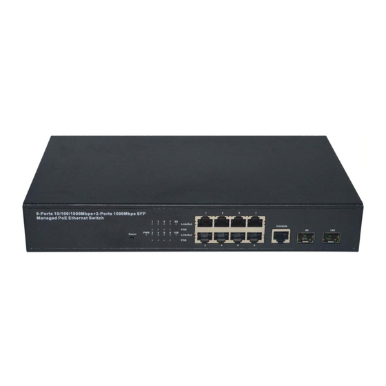
Chapter 1 Product Introduction Congratulations on your purchase of the PoE Web Smart Ethernet Switch. Before you install and use this product, please read this manual carefully for a full understanding of its functions. 1.1 Product Overview The 8-port + 2SFP 10/100/1000M PoE Web Smart Ethernet Switch provides seamless network connection. - Page 6 Figure 1 - Front Panel 10/100/1000Mbps RJ-45 ports (1~8): Designed to connect to the device with a bandwidth of 10Mbps, 100Mbps or 1000Mbps. Each port has a corresponding 10/100/1000Mbps LED. Console port (Console): Designed to connect with the serial port of a computer or a terminal for monitoring and configuring the Switch.
-
Page 7: Rear Panel
(1-8) 1000M: Green Flashing Sending or receiving data A Powered Device is connected to the port, which supply power successfully. No PD is connected to the corresponding Yellow port, or no power is supplied according to the power limits of the port. The PoE power circuit may be in short or Flashing the power current may be overloaded. - Page 8 One AC power cord. One User Manual.
-
Page 9: Chapter 2 Installing And Connecting The Switch
Chapter 2 Installing and Connecting the Switch This chapter describes how to install your PoE Ethernet Switch and make connections to it. Please read the following topics and operate the procedures in the order being presented. 2.1 Installation Please follow the following Instructions in avoid of incorrect installation causing device damage and security threat. -
Page 10: Power On The Switch
Figure 5 - Rack Installation 2.1.3 Power on the Switch The Switch is powered on by connecting it to an outlet using the AC 100-240V 50/60Hz internal high-performance power supply. Please follow the next tips to connect: AC Electrical Outlet: It is recommended to use single-phase three-wire receptacle with neutral outlet or multifunctional computer professional receptacle. -
Page 11: Chapter 3 How To Login The Switch
Chapter 3 How to Login the Switch 3.1 Switch to End Node Use standard Cat.5/5e Ethernet cable (UTP/STP) to connect the Switch to end nodes as described below. Switch ports will automatically adjust to the characteristics (MDI/MDI-X, speed, duplex) of the device to which is connected. Figure 6 - PC Connect Please refer to the LED Indicators. - Page 12 Figure 7- Login Windows Switching language to English. Enter the Username and Password (The factory default Username is admin and Password is admin), and then click “LOGIN” to log in to the Switch configuration window as below.
-
Page 14: Chapter 4 Switch Configuration
Chapter 4 Switch Configuration The Web Smart Ethernet Switch Managed switch software provides rich layer two functionality for switches in your networks. This chapter describes how to use Web-based management interface (Web UI) to this Switch configure managed switch software features. - Page 15 【Parameter Description】 Parameter Description VLAN ID VLAN number, 8GE default VLAN 1 VLAN name VLAN mark Manage IP Manage the IP address of the VLAN device name Switch name Manage VLAN Switches management in use of the VLAN 【Instructions】 Native VLAN: as a Trunk, this port must belong to a Native VLAN. The so-called Native VLAN, refers to UNTAG send/receive a message on the interface, is considered belongs to the VLAN.
-
Page 16: Port
Click “next step” button, into other settings, such as manage ip address set as 192.168.2.11, device name set as switch-123, default gateway with the dns server set as 172.16.1.241. Use 192.168.2.11 to log in, set a new password for 1234. 4.2 PORT Selecting “PORT”... -
Page 17: Basic Config
4.2.1 Basic config Selecting “PORT>Basic Config” in the navigation bar, you can configure Port description, Port speed, Port status, Working mode, Flow control, Cross line order configuration, the following picture: 【Parameter Description】 Parameter Description port Select the current configuration port number port status Choose whether to close link port flow control... -
Page 18: Port Aggregation
【Configuration example】 For example: Setting the Port speed as ‘10M’, Working mode as ‘Duplex’, Flow control as ‘On’, Cross line sequence and Port status as ‘On’. 4.2.2 Port Aggregation In the navigation bar to select “PORT>Port Aggregation”. In order to expand the port bandwidth or achieve the bandwidth of the redundancy backup, the following picture: 【Parameter Description】... -
Page 19: Port Mirroring
4.2.3 Port mirroring In the navigation bar to select “PORT>Port Mirroring”, Open port mirror feature, All the packets on the source port are copied and forwarded to the destination port, destination port is usually connected to a packet analyzer to analyze the source port, multiple ports can be mirrored to a destination port, the following picture: 【Parameter Description】... -
Page 20: Port Rate-Limit
4.2.4 Port rate-limit In the navigation bar to select “PORT>Port Limit”. Limiting the speed of output and input rate of the ports, the following picture: 【Parameter Description】 Parameter Description Input speed limit Set port input speed Output speed limit Set port output speed 【Instructions】... -
Page 21: Storm Control
4.2.5 Storm control In the navigation bar to select “PORT>Storm Control”, to port storm control config, the following ficture: 【Parameter Description】 Parameter Description Broadcast Storm suppression value of the broadcast packets suppression value Multicast suppression Storm suppression value of the multicast packets value Unicast suppression Storm suppression value of the unicast packets... -
Page 22: Port Isolation
Such as: should be forwarded to the port 1-8 of all kinds of packet forwarding rate is 5000 KB/s. 4.2.6 Port isolation In the navigation bar to select “PORT>port isolation”, the following picture: 【Parameter Description】 Parameter Description Source port Choose a port, to configure the isolated port Port will be isolated Isolated port 【Instructions】... -
Page 23: Vlan
Such as: the port 3, 4, 5, and 6 ports isolated. 4.3 VLAN In the navigation bar to select “VLAN”. You can manage the VLAN config, Trunk Settings and Hybrid Settings, the following picture: 4.3.1 VLAN config In the navigation bar to select “VLAN config”, Vlans can be created and set the port to the VLAN (port default state for the access mode), the following picture:... - Page 24 【Parameter Description】 Parameter Description VLAN ID VLAN number, 8GE default VLAN 1 VLAN name VLAN mark VLAN IP address Manage switch ip address 【Instructions】 Management VLAN, the default VLAN cannot be deleted. Add ports as access port, port access mode can only be a member of the VLAN. 【Configuration example】...
-
Page 25: Trunk-Port Setting
4.3.2 Trunk-port setting In the navigation bar to select “VLAN config>Trunk-port setting”, can set port as Trunk Port, the following picture: 【Parameter Description】 Parameter Description Native VLAN Only set one Allowing vlan Can set up multiple 【Instructions】 Native VLAN: As a Trunk, the port will belong to a Native VLAN. The so-called Native VLAN, is refers to UNTAG send or receive a message on the interface, is considered belongs to the VLAN. -
Page 26: Hybrid-Port Setting
4.3.3 Hybrid-port setting In the navigation bar to select “VLAN config>Hybrid-port setting”, Can set the port to take the tag and without the tag, the following picture: 【Instructions】 Hybrid port to packet: Receives a packet, judge whether there is a VLAN information: if there is no play in port PVID, exchanged and forwarding, if have, whether the Hybrid port allows the VLAN data into: if can be forwarded, or discarded (untag on port configuration is not considered, untag configuration only work when to send it a message). - Page 27 This system e0/1 and the receive system e0/2 PC can be exchanged, but when each data taken from a VLAN is different. Data from the pc1, by inter0/1 pvid VLAN10 encapsulation VLAN10 labeled into switches, switch found system e0/2 allows 10 data through the VLAN, so the data is forwarded to the system e0/2, because the system e0/2 VLAN is untagged 10, then switches at this time to remove packet VLAN10 tag, in the form of ordinary package sent to pc2, pc1 - >...
-
Page 28: Fault/Safety
4.4 Fault/Safety In the navigation bar to select “Fault/Safety”, you can set anti attack, channle detection and ACLaccess control configuration . 4.4.1 Anti Attack 4.4.1.1 Anti DHCP Attack In the navigation bar to select “Fault/Safety>Anti Attack>Anti DHCP Attack”, Open the DHCP anti-attack function, intercepting counterfeit DHCP server and address depletion attack packets ban kangaroo DHCP server, the following picture: 【Instructions】... - Page 29 Set the connection router 8 ports for trust, then 6 port is set to the prohibit. Verify source mac F0:DE:F1:12:98:D2,set server ip address to 192.168.2.1. Set option82 information.
-
Page 30: Anti Dos
The port 7 for binding. 4.4.1.2 Anti DOS In the navigation bar to select “Fault/Safety>Anti Attack>Anti DHCP Attack”, Open the anti DOS attack function, intercept Land attack packets, illegal TCP packets, to ensure that the device or the server providing normal service to legitimate users. The following picture: 【Instructions】... -
Page 31: Ipsource Guard
Open the anti DOS attack function, intercept Land attack packets, illegal TCP packets, to ensure that the device or server to provide normal service to legitimate users. 【Configuration example】 Such as:Open the Anti DOS attack function 4.4.1.3 IPsource Guard In the navigation bar to select “Fault/Safety>Anti Attack>Ip Source Guard”, Through the source port security is enabled, on port forwarding the packet filter control, prevent illegal message through the port, thereby limiting the illegal use of network resources, improve the safety of the port, the following picture:... -
Page 32: Anti Three Bind
4.4.1.4 Anti Three Bind In the navigation bar to select “Fault/Safety>Anti Attack>Anti Three Bind”, Automatically detect the mapping relationship of the ports based IP address, MAC address, and then acheive the function of a key binding, the following picture: 【Instructions】 A bond must be bounded before the binding to enable the switch to open, And if you want to access shall be binding and switch the IP address of the same network segment. -
Page 33: Channel Detection
Can check the delete option. 4.4.2 Channel detection 4.4.2.1 Ping testing In the navigation bar to select “Fault/Safety>Channel Detection>Ping testing”. Use ping function to test internet connect and host whether to arrive. The following picture : 【Parameter Description】 Parameter Description destination IP address Fill in the IP address of the need to detect Timeout period Range of 1 to 10... -
Page 34: Tracert Testing
Repeat number Testing number 【Instructions】 Use ping function to test internet connect and host whether to arrive. 【Configuration example】 Such as: PING connect the IP address of the PC. 4.4.2.2 Tracert testing In the navigation bar to select “Fault/Safety>Channel Detection>Tracert testing”, Tracert detection can detect to the destination through the. -
Page 35: Cable Testing
Such as: PING connect the IP address of the PC. 4.4.2.3 Cable testing In the navigation bar to select “Fault/Safety>Channel Detection>Cable testing”, Can detect connection device status, the following picture: 【Configuration example】... -
Page 36: Acl
4.4.3 ACL In the navigation bar to select “Fault/Safety>ACL”, ACL rules can be applied to the port and set the effective time. 【Instruction】 The ACL rules are sequenced, row in front of the match will be priority rule. If there are a lot of policy entries, the operation time will be relatively long. -
Page 37: Mstp
4.5 MSTP In the navigation bar to select ”MSTP”, you can set to the MSTP Region and MSTP Bridge configuration. -
Page 38: Mstp Region
4.5.1 MSTP Region In the navigation bar to select ”MSTP>MSTP Region”. Can modify the domain and domain name, add instance is mapped to a VLAN. The following picture. 【Parameter Description】 Parameter Description Region name Configure the region name Revision level Parameter configuration revision level Instance ID Select configuration instance ID... -
Page 39: Mstp Bridge
4.5.2 MSTP Bridge In the navigation bar to select ”MSTP>MSTP Bridge”. Can be related to bridge, port configuration, the following picture: 【Parameter Description】 Parameter Description inst-priority Whether open instance priority setting Instance ID Select the created instance id is configured enable Whether to open the STP bridge function Priority setting bridge example, the default... - Page 40 Hello-time Switches sends bpdus in packet interval Ports are not yet received a message in the time, Max-age will initiate topology changes Forward-delay The state of the port switch time Set port instance priority, defaults to 128, you must Port-priority enter multiple of 16, the range of 0-240 Path-cost Configure port costs...
-
Page 41: Dhcp Relay
Set MSTP has launched port configuration, select the created instance, set priority (port configuration is not online, on-line configuration will only take effect, can click on the "view the current configuration" button to view the configured completed). 4.6 DHCP RELAY In the navigation bar to select ”DHCP RELAY”, you can set to the DHCP relay and option82. -
Page 42: 0Ption82
【Parameter Description】 Parameter Description IP address DHCP server address status Invalid and vaild 【Instruction】 If the function of relay agent is turned on, Then the received DHCP broadcast message will be sent to the server in the form of unicast. DHCP server and IP switches in the same network will take effect. - Page 43 【Parameter Description】 Parameter Description VLAN id the DHCP request message in the VLAN, value range is 1 ~ 4094 Circuit control Circuit ID to populate the user custom content, scope of string length is 3 ~ 63 Proxy remote Configuration ASCII remote id string value, the length of the range of 1 ~ 63 IP address Decimal IP address...
-
Page 44: Qos
4.7 QoS In the navigation bar to select ”QOS”, you can set to the Remark, Queue Config and Mapping the Queue. 4.7.1 Remark In the navigation bar to select ”QOS>Remark”, According to the rules for port traffic bag tag or queue map. The following picture. 【Parameter Description】... -
Page 45: Queue Config
Choose always said - match the match, all the data for tags Operation type Choose can be set to equal matching rules, comply with the rules of heavy tag data Adaptable to the rules of the heavy tag which data is mapped to a Server class mapping queue Conform to the rules of heavy tag data to the marked priority... -
Page 46: Mapping The Queue
In the navigation bar to select ”QOS>Queue Config”. Can be set up queue scheduling policy. The following picture: 【Parameter Description】 Parameter Description Can choose four kinds of modes: RR round-robin scheduling SP absolute priority scheduling WRR weighted round-robin scheduling Scheduling strategy WFQ weighted fair scheduling Set the weights of each queue, they will be in proportion to occupy WRR-weights... -
Page 47: Service Class Queue Mapping
4.7.3.1 Service class queue mapping In the navigation bar to select ”QOS>Mapping the Queue”, Service category can be mapped to the corresponding queue. The following picture. 【Parameter Description】 Parameter Description Server ID COS the VLAN priority fields (0 to 7) Queue ID Set each cosine value mapping queue number (0 to 7) 【Configuration example】... -
Page 48: Port To Service Class Mapping
【Parameter Description】 Parameter Description Server list DSCP field has seven (0-63) is divided into four tables Map the DSCP to COS fields (0 to 7), based on the cosine is Queue ID mapped to a queue 【Instruction】 Cos priority is greater than the DSCP, DSCP priority is greater than the port. 【Configuration example】... - Page 49 【Parameter Description】 Parameter Description Port Select the port number (1-10) Mapped to the service ID, and then according to the service ID Service ID into the queue 【Instruction】 Cos priority is greater than the DSCP, DSCP priority is greater than the port. 【Configuration example】...
-
Page 50: Address Table
4.8 Address table In the navigation bar to select ”Address table”, you can set to MAC add and delete, MAC study and Aging and MAC address filtering. 4.8.1 Mac add and delete In the navigation bar to select ”Address table>Mac add and delete”. You can add static Mac and delete Mac and view to the current of the Mac address table. - Page 51 【Parameter Description】 Parameter Description Can choose to clear the multicast Mac address, clear dynamic unicast Mac address, clear static unicast Mac address, clear the Clear Mac specified Mac address, Mac address table Fill in the need to add or delete VLAN id, not create vlans to VLAN create can only take effect 【Instruction】...
-
Page 52: Mac Study And Aging
4.8.2 Mac study and aging In the navigation bar to select ”Address table>Mac study and aging”. Can be set up port Mac address study limit and Mac address aging time. The following picture: 【Parameter Description】 Parameter Description Mac address Range 0-8191,default 8191 Mac address study limit Default 300... -
Page 53: Mac Address Filtering
The port equipment dropped or to learn the Mac address after 2 minutes from the Mac address table automatically disappear. 4.8.3 Mac address filtering In the navigation bar to select ”Address table>Mac address flitering”. Can be filtered according to the condition does not need the Mac address. The following picture: 【Parameter Description】... -
Page 54: Snmp
4.9 SNMP In the navigation bar to select ”SNMP”, you can set to the Snmp config and Rmon config. 4.9.1 Snmp config 4.9.1.1 Snmp config In the navigation bar to select ”Snmp >Snmp config”, you can Snmp function enable.the following picture: 【Instruction】... -
Page 55: Community Config
4.9.1.2 Community config In the navigation bar to select ”Snmp >Snmp config>community config”. Can specify group access. The following picture. 【Parameter Description】 Parameter Description Community string, is equal to the NMS and Snmp agent group communication between the password Read-only: specify the NMS (Snmp host) of MIB variables can only be read, cannot be modified Read-only can write: specify the NMS (Snmp host) of MIB Access authority... -
Page 56: Group Config
【Parameter Description】 Parameter Description View name Wiew mane include Indicate the MIB object number contained within the view exclude Indicate the MIB object son number was left out of view MIB subtree OID View the associated MIB object, is a number of MIB subtree mask MIB OID mask 【Instruction】... - Page 57 【Parameter Description】 Parameter Description Group name Group name Attestation not only encryption: this group of users transmission of the message need to verify the data don't need to confidential No authentication encryption: this group of users' messages don't need to verify data transmission also does not need to be Security level kept secret Both authentication and encryption: this group of users need to...
-
Page 58: User Config
4.9.1.5 User config In the navigation bar to select ”Snmp>Snmp Config>User Config”, setting Snmp user. The following picture: 【Parameter Description】 Parameter Description User name,range 1-16 User name Attestation not only encryption: this group of users transmission of the message need to verify the data don't need to confidential No authentication encryption: this group of users' messages Security level... -
Page 59: Trap
4.9.1.6 Trap In the navigation bar to select ”Snmp>Snmp Config>Trap”. Can specify sent the trap messages to Snmp host (NMS). The following picture: 【Parameter Description】 Parameter Description Destination ip address Snmp host ipv4 address Security name Snmp user name version V1、V2、V3 Specified using AES encryption protocol or DES encryption Security mode... -
Page 60: Rmon Config
4.9.2 Rmon Config 4.9.2.1 Statistics Group In the navigation bar to select ”Snmp>Rmon Config>Statistics Group”, Set an Ethernet interface statistics. The following picture: 【Parameter Description】 Parameter Description The index number, the value range of statistical information index table is 1 ~ 65535 Interface mane To monitor the source port ower... -
Page 61: History Group
4.9.2.2 History Group In the navigation bar to select ”Snmp>Rmon Config>History Group”. Record the history of an Ethernet interface information. The following picture. 【Parameter Description】 Parameter Description Historical control table item index number, value range is 1 ~ index 65535 Interface name To record the Ethernet interface Set the history control table item of the corresponding table... -
Page 62: Event Group
Such as: monitor Ethernet port 4 historical information. 4.9.2.3 Event Group In the navigation bar to select ”Snmp >Rmon Config>Event Group”. The way in which define events trigger and record them. The following picture. 【Parameter Description】 Parameter Description The index number, the value range of the event table is 1 ~ index 65535 The Trap events, when the event is triggered, the system will... -
Page 63: Alarm Group
4.9.2.4 Alarm Group In the navigation bar to select ”Snmp>Rmon Config>Alarm Group”, define alarm group. The following picture. 【Parameter Description】 Parameter Description index The alarm list items index number, value range is 1 ~ 65535 Statistical type values :3:DropEvents. 4:Octets. 5:Pkts. -
Page 64: System
【Configuration example】 Such as: new statistics group of 77 and the event group 345, set up more than 12 and below the lower limit 3, Beyond the scope of alarm. 4.10 SYSTEM In the navigation bar to select ”SYSTEM”, you can set to the System Config, System Update, Config Management, Config Save, Administor Privileges and Info Collect. - Page 65 【Parameter Description】 Parameter Description Device name switch name Manage VLAN Switches use VLAN management Manage ip Switch IP address management timeout Don't use more than login timeout after login to log in again 【Configuration example】 Such as: Set up the VLAN 2 is management VLAN, should first created vlan 2 the VLAN Settings and set a free port in the VLAN 2.
- Page 66 Insert the PC interface 9 or 10 ports, set up the management IP for 192.168.2.12, device name is yoyo, timeout for 20 minutes, Jumboframe for 5000.
-
Page 67: System Restart
Use 192.168.1.12 logging in, sets the system time. 4.10.1.2 System restart In the navigation bar to select ”SYSTEM>System Config>System restart”, equipment can be restarted. The following picture: 【Instruction】 Click the button to restart the switch. The restart process may take 1 minute. Please wait patiently. -
Page 68: Password Change
4.10.1.3 Password change In the navigation bar to select ”SYSTEM>System Config>Password change”, The password change to equipment. The following picture: 【Instruction】 If you set a new Web login password, then log in again after seting the new password. Password can not contain Chinese, full-width characters, question marks and spaces. -
Page 69: Telnet Login
【Instruction】 Configure the user to be able to switch through the SSH login device. 【Configuration example】 Such as: SSH open, you can CRT to log in. 4.10.1.5 Telnet login In the navigation bar to select ”SYSTEM>system config>Telnet login”. Telnet open. The following picture: 【Instruction】... -
Page 70: System Log
4.10.1.6 System log In the navigation bar to select ”SYSTEM>Password change>System log”, to view the log and set up the log server. The following picture: 【Parameter Description】 Parameter Description Log switch Open and close Server ip Appoint to server address Send log level Enter the required query of characters 【Instruction】... -
Page 71: System Upgrade
4.10.2 System Upgrade In the navigation bar to select “SYSTEM>system upgrade”, Optional upgrade file to upgrade. the following picture. 【Instruction】 please confirm that the upgraded version of the same model and the same model. in the upgrade process, you may encounter flash to make the page is temporarily unable to respond to the page, this time can not power off or restart the device, until prompted to upgrade successfully. -
Page 72: Current Configuration
4.10.3.1 Current configuration In the navigation bar to select “SYSTEM>Config Management>Current configuration”, can import and export configuration files, the backup file.The following picture: 【Instruction】 Import process can not be closed or refresh the page, or import will fail. After the introduction of configuration, to enable the new configuration, please in this page Restart device Otherwise configuration does not take effect. -
Page 73: Configuration Backup
Backup. 4.10.3.2 Configuration backup In the navigation bar to select “SYSTEM>Config Management>Configuration backup”, you can configure backup file. The following picture:... -
Page 74: Restore Factory Configuration
【Instruction】 Operating this page should be in the current configuration page first, the backup file. 【Configuration example】 Such as: restore backup. 4.10.3.3 Restore factory configuration In the navigation bar to select “SYSTEM>Config Management>Restore factory configuraton”. Can export the current configuration and restore factory configuration. The following picture: 【Instruction】... -
Page 75: Config Save
system has a useful configuration, you can export the current configuration and then restore the factory configuration. 【Configuration example】 Such as: restore configuration can be the guide before they leave the current configuration. 4.10.4 Config Save In the navigation bar to select “SYSTEM>Config Save”, you can save current configuration. -
Page 76: Administrator Privileges
4.10.5 Administrator Privileges In the navigation bar to select “SYSTEM>Administrator Privileges”, Configurable ordinary users. The following picture. 【Instruction】 This page only the super administrator admin can access, for the management of users and visitors. The user can log on Web management system to carry on the daily maintenance to the equipment. - Page 77 【Instruction】 Collect useful infomation, it may take a few moment. 【Configuration example】 Such as: click on "Collect" button.
-
Page 78: Appendix: Technical Specifications
Appendix: Technical Specifications Hardware Features IEEE 802.3i、IEEE 802.3u、 IEEE 802.3ab、IEEE 802.3x、 Standards and Protocols IEEE 802.3z、 IEEE 802.3at、 IEEE 802.3af、 IEEE 802.1q、 IEEE 802.1p 8 x 10/100/1000Mbps Auto-Negotiation ports Interface 2 x 1000Mbps SFP ports 1 x Console port 10Base-T: UTP category 3, 4, 5 cable (maximum 100m) 100Base-Tx: UTP category 5, 5e cable (maximum 100m) 1000Base-T: UTP category 5e, 6 cable (maximum 100m) Network Media... - Page 79 Port Monitor Port rate-limit MAC filtering The ARP deception, the network cheating Filtering the IP port Static binding IP and MAC Three layers of functional Arp trust port Static routing capacity Ping and Traceroute ...
- Page 80 www.morrelltelecom.com sales@morrelltelecom.com morrelltelecom...
Need help?
Do you have a question about the SW-MNG-8GE2GSFP-8POE and is the answer not in the manual?
Questions and answers