Table of Contents
Advertisement
Quick Links
Advertisement
Table of Contents

Subscribe to Our Youtube Channel
Related Manuals for Drazice BTO 5UP


Summary of Contents for Drazice BTO 5UP
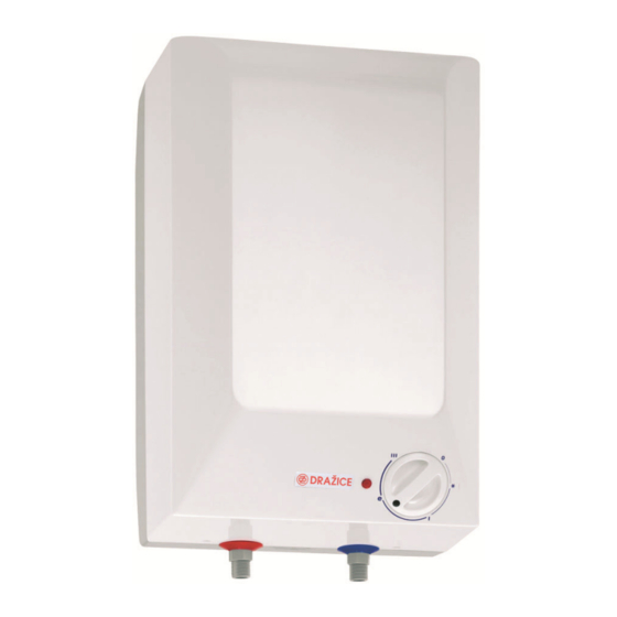
- Page 1 Operation and Installation Manual ELECTRIC WATER HEATER BTO 5 IN/UP BTO 10 IN/UP Družstevní závody Dražice – strojírna s.r.o. (Works Cooperative - Dražice – Machine Plant, Ltd.) Dražice 69 29471 Benátky nad Jizerou Tel.: 326 370 911, Fax: 326 370 980 www.dzd.cz dzd@dzd.cz...
-
Page 2: Table Of Contents
Read carefully the below instructions prior to the installation of the water heater. INFORMATION LEAFLET pursuant to Directive No. 442//2004 Coll., and Annex No.7 Heater types Energy Heat losses Nominal Tim e of Electricity Heat losses efficiency Wh/24hr/l capacity (l) content consum ption kWh/24hr... -
Page 3: Product Accessories
1. PRODUCT ACCESSORIES The product is packed together with service instructions and list of servicing organisations. For non-pressure connection, no safety valve is used; the function of it is performed by a non-pressure combination faucet. The package contains anchors and fasteners to mount the heater. 2. -
Page 4: Plumbing Fixture
7. PLUMBING FIXTURE The heater is designed for flow (non-pressurised) plumbing system. This system enables water withdrawal from one point only. Connection has to be performed as indicated on the figure for connecting to water supply network. For flow connection system you need to use a combination faucet designed to this purpose. Water inflow and outflow is indicated with different colours on the heater tubes. -
Page 5: Heater Commissioning
yellow-green protective conductor on minimum section 4 mm2. Access to the electric part of the heater is enabled only upon disconnecting the heater from power supply and unscrewing the guard of the heater. The degree of protection of electric parts of the heater is IP 24. Respect the rules of protection against electricity injuries in accordance with ČSN 33 2000–4-41. -
Page 6: Functional Defects
11. FUNCTIONAL DEFECTS Defect Failure Wat er in the tank is cold LED is on - heating element failure Wat er in the tank is not warm enough LED is on - heating element failure Wat er in the tank is cold LED is not on - operating thermostat failure safet y thermostat shut of f... -
Page 7: Installation Regulations
14. INSTALLATION REGULATIONS Regulations and instructions that must be obeyed during mounting the heater to power network: For the electrical network ČSN 33 2180 - Connecting of electric devices and appliances ČSN 33 2000-4-41 - Low voltage electric installations Protective measures to ensure safety – Protection against electric shock ČSN 33 2000-5-51 - Electric installations of buildings ČSN 33 2000-7-701 - Low voltage electric installations Single-purpose devices and devices in special premises -... - Page 8 Fig. 1 Heater Dimensions BTO 5 UP BTO 5 IN BTO 10 UP BTO 10 IN BTO 5 UP BTO 5 IN BTO 10 UP BTO 10 IN Fig. 2 Wiring scheme Explanation: 1 - Thermostat failure 2 - Thermal fuse, non-reversible 3 - Heating element 4 - Operation indicator 5 –...
Need help?
Do you have a question about the BTO 5UP and is the answer not in the manual?
Questions and answers