Table of Contents
Advertisement
Quick Links
SERVICE MANUAL
10
2003
52169
TV CATV VCR DVD
ASPECT
MULTI SCREEN
SPLIT
INDEX
FREEZE
SWAP
SELECT
INPUT 1
V1
1
2
3
INPUT 2
V2
4
5
6
INPUT 3
V3
7
8
9
INPUT 4
RETURN+
V4
100+
0
TV
THEATER
NATURAL
VIDEO
DIGITAL-IN
PRO
CINEMA
STATUS
D-IN
SLEEP TIMER DISPLAY SOUND
LIGHT
+
MUTING
C.C.
C.C.
CH
VOL
OK
VOL
CH
MENU
BACK
VCR CHANNEL
VCR DVD
PREV NEXT
POWER
TV VCR
REW
PLAY
FF
REC
STOP
PAUSE
OPEN CLOSE
STILL PAUSE
RM-C13G
1
PRECAUTION. . . . . . . . . . . . . . . . . . . . . . . . . . . . . . . . . . . . . . . . . . . . . . . . . . . . . . . . . . . . . . . . . . . . . . . . . 1-3
2
SPECIFIC SERVICE INSTRUCTIONS . . . . . . . . . . . . . . . . . . . . . . . . . . . . . . . . . . . . . . . . . . . . . . . . . . . . . . 1-6
3
DISASSEMBLY . . . . . . . . . . . . . . . . . . . . . . . . . . . . . . . . . . . . . . . . . . . . . . . . . . . . . . . . . . . . . . . . . . . . . . 1-10
4
ADJUSTMENTS . . . . . . . . . . . . . . . . . . . . . . . . . . . . . . . . . . . . . . . . . . . . . . . . . . . . . . . . . . . . . . . . . . . . . . 1-21
5
TROUBLESHOOTING . . . . . . . . . . . . . . . . . . . . . . . . . . . . . . . . . . . . . . . . . . . . . . . . . . . . . . . . . . . . . . . . . 1-55
COPYRIGHT © 2003 VICTOR COMPANY OF JAPAN, LIMITED
PDP COLOR TELEVISION
PD-42WX84
VM-42WX84
[PLASMA DISPLAY UNIT]
TABLE OF CONTENTS
/SJ
BASIC CHASSIS
TU-42WX84
[RECEIVER UNIT]
SB3
No.52169
2003/10
Advertisement
Chapters
Table of Contents
Troubleshooting

Related Manuals for JVC PD-42WX84SJ


Summary of Contents for JVC PD-42WX84SJ
-
Page 1: Table Of Contents
SERVICE MANUAL PDP COLOR TELEVISION 52169 2003 PD-42WX84 BASIC CHASSIS TV CATV VCR DVD ASPECT MULTI SCREEN SPLIT INDEX FREEZE SWAP SELECT INPUT 1 INPUT 2 INPUT 3 INPUT 4 RETURN+ 100+ THEATER NATURAL VIDEO DIGITAL-IN CINEMA STATUS D-IN SLEEP TIMER DISPLAY SOUND LIGHT MUTING C.C. - Page 2 SPECIFICATION Items Contents Dimensions (W × H × D) Plasma display unit 116.0cm × 79.8cm × 30.8cm (45-11/16 × 31-7/16 × 12-3/16") [with the stand] 116.0cm × 73.1cm × 9.8cm (45-11/16 × 28-13/16 × 3-7/8") [main TV body] Receiver unit 43.5cm × 9.9cm × 38.2cm (17-3/16 × 3-15/16 × 15-1/16") Mass Plasma display unit 48kg (106lbs) [with the stand] 38kg (84lbs) [main TV body]...
-
Page 3: Precaution
SECTION 1 PRECAUTION SAFETY PRECAUTIONS (1) The design of this product contains special hardware, many (9) Isolation Check (Safety for Electrical Shock Hazard) circuits and components specially for safety purposes. For After re-assembling the product, always perform an isolation continued protection, no changes should be made to the original check on the exposed metal parts of the cabinet (antenna design unless authorized in writing by the manufacturer. - Page 4 INSTALLATION 1.2.1 HEAT DISSIPATION 1.2.2 INSTALLATION REQUIREMENTS If the heat dissipation vent behind this unit is blocked, cooling Ensure that the minimal distance is maintained, as specified efficiency may deteriorate and temperature inside the unit will below, between the unit with and the surrounding walls, as well rise.
- Page 5 HANDLING FOR PLASMA DISPLAY PANEL 1.3.4 OPTICAL FILTER (PANEL FILTER) Avoid placing the unit under direct sunlight over a prolonged 1.3.1 PRECAUTIONS DURING NOTES FOR TRANSPORTATION period of time. This may cause the optical filter to deteriorate in When transporting the display unit, pressure exerted on the quality and color.Clean the filter surface by wiping it softly lightly internal PDP (Plasma Display Panel) due to improper handling with outing flannels a soft and lightly fuzz cloth (such as...
-
Page 6: Specific Service Instructions
SECTION 2 SPECIFIC SERVICE INSTRUCTIONS FEATURES 2.1.1 HIGH-DEFINITION IMAGE TECHNOLOGY (DIST) DIST is a digital high-definition image processing technology that converts various image input signals such as NTSC(480i), 480p, 720p, and 1080i into a format with the best resolution for a display device such as a plasma display panel, and displays high- definition images. - Page 7 TECHNICAL INFORMATION 2.2.1 PDP STRUCTURE AND CHARACTERISTIC This unit (Display Unit) uses the flat type panel PDP (Plasma Display Panel), instead of the conventional CRT (Cathode Ray Tube), as a display unit. 2.2.1.1 PIXEL (CELL) ARRAY PDP is constructed by sealing the xenon, which emits neon and ultraviolet rays for discharging purpose, in between the electrodes lay on the front glass substrate and rear glass substrate.One pixel is composed of 3 RGB cells, with cell pitch of 0.304mm (1 pixel 0.897mm) horizontally and 0.693mm vertically.The cell is arrayed in each RGB color as shown in Fig.
- Page 8 2.2.2 MAIN MI-COM FUNCTIONAL TABLE [RECEIVER UNIT] Pin No. Terminal name Port name Function BS-RxD SBO0 PDP communication /MICON_V /VSYNC Vertical sync for OSD LB_PRO Low B protection detect [Detection : H] Not used /RST /RST Reset for CPU [Reset : L] CONV.BUSY P52 IRQ4 Not used...
- Page 9 Pin No. Terminal name Port name Function PDP-Tx P25 SBD1 PDP communication SBT1 SBT1 Port for writing on board Not used Not used Not used BS1.5CTL Not used /DVI_RST PWM2 Not used DVI_HP PWM1 DVI Connection detect [Connect : H] /MDR_CON PWM0 Panel connection detect [Connect : L]...
-
Page 10: Disassembly
SECTION 3 DISASSEMBLY DISASSEMBLY PROCEDURE (DISPLLAY UNIT) 3.1.2 REMOVING THE SIDE SPEAKER COVER (Fig.1) (1) Remove the 4 screws [ C ]. • Prior to assembly/disassembly procedure of the set, be sure to (2) Take out the SIDE SPEAKER COVER. disconnect the power cord from the wall outlet. - Page 11 3.1.3 REMOVING THE DD SPEAKER ASS'Y (Fig.1, Fig.2) 3.1.9 REMOVING THE LINE FILTER PWB (Fig.2) • Remove the REAR COVER. NOTE: • Remove the SHIELD COVER. Please do not disassembly DD SPEAKER ASS'Y. A performance • Remove the TERMINAL BRACKET. may be influenced if it disassembly.
- Page 12 3.1.12 REMOVING THE CHASSIS BASE (Fig.3) 3.1.14 REMOVING THE TEMP. SENSOR PWB (Fig.3) • Remove the REAR COVER. • Remove the REAR COVER. • Remove the SHIELD COVER. (1) Remove the [ ] connector on the TEMP. SENSOR PWB. • Remove the TERMINAL BRACKET. (2) Remove the screw [ V ].
- Page 13 3.1.18 THE SIDE BLACKET (Fig.4) 3.1.19 REMOVE THE FRONT FILTER (Fig.4) • Remove the REAR COVER. • Remove the REAR COVER. • Remove the SHIELD COVER. • Remove the SHIELD COVER. • Remove the TERMINAL BRACKET. • Remove the TERMINAL BRACKET. •...
- Page 14 3.1.20 DISASSEMBLY PDP UNIT UNIT (Fig.5) 3.1.20.1 REMOVING THE SMPS PWB 3.1.20.6 REMOVING THE LOGIC-MAIN PWB • Remove the REAR COVER. • Remove the REAR COVER. (1) Remove the CN8007/CN8008/CN8004/CN8005/CN8006/ • Remove the CHASSIS BASE. CN8003/CN8009/CN8002 connectors on the SMPS PWB. (1) Remove the CN2001/CN2002/CN2003/CN2004/CN2005/ (2) Remove the 8 screws [ g ].
- Page 15 CN9005 CN402 CN401 CN9007 CN8003 CN8009 CN9006 CN8005 CN8002 CN9003 CN8006 CN8001 LA01 CN9002 CN8004 CN9001 CN2005 CN9004 CN8007 CN2001 CN2004 CN807 CN8008 CN2007 CN2006 CN5008 CN5001 CN5401 CN2002 CN2003 CN5404 CN5402 CN4001 CN5407 CN4003 CN5403 CN5405 CN4004 CN5505 CN5501 CN5507 CN4002 CN5502...
- Page 16 DISASSEMBLY PROCEDURE (RECEIVER UNIT) (Fig. 6) • Make sure that the power cord is pulled out from the AC wall • Remove the DIGITAL INPUT MODULE. socket. • Remove the MI-COM & DIST MODULE PWB and DIST RELAY PWB. 3.2.1 REMOVING THE TOP COVER (1) Remove the [ CN1001 ] and [...
- Page 17 (x4) TOP COVER (x3) (x2) DIST HOLDER (x2) (x2) CN100A DIST RELAY PWB CHASSIS BRACKET MI-COM & DIST MODULE PWB (x2) RECEIVER PWB (x5) FRONT PANEL (BACK SIDE) RECEIVER POWER PWB (x6) CN1001 CN1002 CN1006 DAMPER FRONT CN90PW PANEL CN1005 Claw (x1) CN90E1...
- Page 18 REPLACEMENT OF MEMORY IC This unit uses the nonvolatile memory IC. The memory IC memories data for video-chroma and drive circuits. To replace the memory IC without the data written, malfunctions might occurred while power is on, and the normal image might not appear. When replacing the memory IC, be sure to use the IC written with the initial values of data.
- Page 19 3.3.2 SETTINGS OF FACTORY SHIPMENT 3.3.2.1 BUTTON OPERATION (DISPLAY UNIT) 3.3.2.2 REMOTE CONTROL DIRECT OPERATION Setting item Setting value Setting item Setting value INPUT INPUT CHANNEL CHANNEL CABLE-02 VOLUME VOLUME MUTING DISPLAY SOUND ASPECT PANORAMA OFF TIMER VIDEO STATUS DINAMIC NATURAL CINEMA AUTO 3.3.2.3...
- Page 20 REPLACEMENT OF CHIP COMPONENT 3.4.1 CAUTIONS (1) Avoid heating for more than 3 seconds. (2) Do not rub the electrodes and the resist parts of the pattern. (3) When removing a chip part, melt the solder adequately. (4) Do not reuse a chip part after removing it. 3.4.2 SOLDERING IRON (1) Use a high insulation soldering iron with a thin pointed end of it.
-
Page 21: Adjustments
SECTION 4 ADJUSTMENTS ADJUSTMENT PREPARATION (1) There are 2 ways of adjusting this TV : One is with the (7) Preparation for adjustment. Unless otherwise specified in REMOTE CONTROL UNIT and the other is the the adjustment items, preset the following functions with conventional method using adjustment parts and the REMOTE CONTROL UNIT. - Page 22 MAIN PARTS LOCATIONS (DISPLAY UNIT) 1-22 (No.52169)
- Page 23 SERVICE MENU SCREEN DO NOT ADJUST MAIN MENU 4.MEMORY SETUP ADDRESS(H) 0000 1.PICTURE/SOUND 7.PANEL 2.YC SEP 8.PP 3.WHITE BALANCE 9.IP 4.MEMORY SETUP 0.HDMI 5.RF AFC 6.DD/CM 5.RF AFC TOO HIGH GOOD TOO LOW TUNER MAIN FINE 1.PICTURE/SOUND 6.DD/CM NTSC CINE ST L FL MUTE NTSC CINE ST L FL MUTE VOLUME(+/-) key DDT01~34...
- Page 24 BASIC OPERATION OF THE SERVICE MODE [USING REMOTE CONTROL] 4.6.1 HOW TO ENTER THE SERVICE MODE MAIN MENU MAIN MENU NOTE: Ensure that the cursor (arrow) of the User Menu screen is pointing at Picture Control. Before entering the SERVICE MODE, confirm that the setting 1.PICTURE/SOUND 7.PANEL of TV / CATV SW of the REMOTE CONTROL UNIT is at the...
- Page 25 4.6.4 SETTINGS OF THE SERVICE MENUS 4.6.4.1 [1. PICTURE/SOUND (Picture/sound setting)] Adjusts output data to ports such as Audio, Drive, Video and (2) Adpect / Multi (8) I-P interpolation MODE others (Item F): (1) Signal Type (3) Picture Selection (7) Data Saving Method (1) SIGNAL TYPE The signal currently displayed on the screen is displayed.
- Page 26 INITIAL SETTING VALUES IN THE SERVICE MODE • Perform fine-tuning based on the "initial values" using the remote control when in the Service mode. • The "initial values" serve only as an indication rough standard and therefore the values with which optimal display can be achieved may be different from the default values.
- Page 27 Setting value Item Variable Item NTSC 525i 525p 750p/1125i range STANDARD THEATER STANDARD THEATER STANDARD THEATER STANDARD THEATER S09 BYGN 000~255 S10 OF BYGN -127~128 (---) (---) (---) (---) (---) (---) (---) (---) S11 RYAXIS -127~128 +006 +006 +006 S12 MTX 000~003 Item Variable...
- Page 28 Setting value Item Variable Item range STANDARD THEATER (Not used) 000~015 (Not used) 000~015 Setting value Item Variable Item NTSC 525i/525p 750p/1125i range STANDARD THEATER STANDARD THEATER STANDARD THEATER S48 DCTRAN 000~015 Setting value Item Variable Item range SPLIT-SCREEN REGULAR S49 HSTR 000~001 S50 HSTR...
- Page 29 Item Variable Item Setting value range S70 TINTON 001~001 S71 DRIVER 001~255 S72 DRIVEG 001~255 S73 DRIVEB 001~255 S74 EECONT 001~031 S75 EEBRT 001~031 Setting value Item Variable Item range NTSC 525i/525p 750/1125i S76 EETBRT -127~128 S77 EETCONT -127~128 Setting value Item Variable Item...
- Page 30 Item Variable Item Variable Item Setting value Item Setting value range range (Not display) 000~127 (Not display) 000~255 (Not display) 000~063 (Not display) 000~255 (Not display) 000~127 (Not display) 000~255 (Not display) 000~063 (Not display) 000~255 (Not display) 000~031 (Not display) 000~001 (Not display) 000~127...
- Page 31 Setting value Item Variable Item DIGITAL range NTSC 525i 525p 750p 1125i 525i 525p 750p 1125i (Not display) 000~003 (Not display) 000~001 (Not display) 000~063 Item Variable Item Setting value range (Not display) 000~001 (Not display) 000~007 OUT LV. 000~255 LIMIT B 000~255 LIMIT A...
- Page 32 4.7.2 [2.YC SEP] NOTE : Setting Item No. Item Variable range Initial setting value is reference value at following condition. value INPUT SIGNAL : NTSC YCM039 (Not display) 000~127 ASPECT : FULL YCM040 (Not display) 000~003 MULTI-SCREEN : SINGLE VIDEO STATUS : STANDARD YCM041 (Not display)
- Page 33 Setting Setting Item No. Item Variable range Item No. Item Variable range value value YCM083 (Not display) 000~001 YCM128 (Not display) 000~001 YCM084 (Not display) 000~063 YCM129 (Not display) 000~001 YCM085 (Not display) 000~001 YCM130 (Not display) 000~003 YCM086 (Not display) 000~001 YCM131 (Not display)
- Page 34 Setting Setting Item No. Item Variable range Item No. Item Variable range value value YCM173 (Not display) 000~007 YCS031 (Not display) 000~001 YCM174 (Not display) 000~255 YCS032 (Not display) 000~003 YCM175 (Not display) 000~001 YCS033 (Not display) 000~001 YCM176 (Not display) 000~001 YCS034 (Not display)
- Page 35 4.7.3 [3.WHITE BALANCE] Setting Item No. Item Variable range value NOTE : Initial setting value is reference value at following condition. YCS076 (Not display) 000~001 INPUT SIGNAL : NTSC YCS077 (Not display) 000~001 ASPECT : FULL YCS078 (Not display) 000~001 MULTI-SCREEN : SINGLE YCS079...
- Page 36 Setting Setting Item No. Item Variable range Item No. Item Variable range value value DDT30 (Not display) 000~001 CMT39 (Not display) 000~255 DDT31 (Not display) 000~007 CMT40 (Not display) -128~+127 DDT32 (Not display) 000~255 CMT41 (Not display) -128~+127 +010 DDT33 (Not display) 000~255 CMT42...
- Page 37 Setting Setting Item No. Item Variable range Item No. Item Variable range value value DDP25 (Not display) 000~015 PDB011 (Not display) 000~001 DDP26 (Not display) 000~015 PDB012 (Not display) 000~001 DDP27 (Not display) 000~015 PDB013 (Not display) 000~031 DDP28 (Not display) 000~015 PDB014 (Not display)
- Page 38 Setting Setting Item No. Item Variable range Item No. Item Variable range value value ADM020 (Not display) 000~001 PPB019 (Not display) 000~0FF ADM021 (Not display) 000~001 PPB020 (Not display) 000~0FF ADM022 (Not display) 000~001 PPB021 (Not display) 000~01F ADM023 (Not display) 000~001 PPB022 (Not display)
- Page 39 Setting Setting Item No. Item Variable range Item No. Item Variable range value value PPD014 (Not display) 000~00F IPA025 (Not display) 000~001 PPD015 (Not display) 000~0FF IPA026 (Not display) 000~03F PPD016 (Not display) 000~00F IPA027 (Not display) 000~003 PPD017 (Not display) 000~0FF IPA028 (Not display)
- Page 40 Setting Setting Item No. Item Variable range Item No. Item Variable range value value IPA070 (Not display) 000~255 IPA115 (Not display) 000~00F IPA071 (Not display) 000~00F IPA116 (Not display) 000~0FF IPA072 (Not display) 000~0FF IPA117 (Not display) 000~001 IPA073 (Not display) 000~001 IPA118 (Not display)
- Page 41 Setting Setting Item No. Item Variable range Item No. Item Variable range value value IPB038 (Not display) 000~007 IPC001 (Not display) 000~003 IPB039 (Not display) 000~00F IPC002 (Not display) 000~0FF IPB040 (Not display) 000~00F IPC003 (Not display) 000~001 IPB041 (Not display) 000~00F IPC004 (Not display)
- Page 42 4.7.8 [0.HDMI] *All the values are fixed values. Setting Item No. Item Variable range value Setting Item No. Item Variable range value IPD001 (Not display) 000~0FF HDM001 (Not display) 000~001 IPD002 (Not display) 000~0FF HDM002 (Not display) 000~001 IPD003 (Not display) 000~0FF HDM003 (Not display)
- Page 43 Setting Setting Item No. Item Variable range Item No. Item Variable range value value HDM046 (Not display) 000~001 RHD009 (Not display) HDM047 (Not display) 000~015 RHD010 (Not display) HDM048 (Not display) 000~255 RHD011 (Not display) HDM049 (Not display) 000~255 RHD012 (Not display) HDM050 (Not display)
- Page 44 Setting Setting Item No. Item Variable range Item No. Item Variable range value value RHD054 (Not display) RHD009 (Not display) RHD055 (Not display) RHD100 (Not display) RHD056 (Not display) RHD101 (Not display) RHD057 (Not display) RHD102 (Not display) RHD058 (Not display) RHD103 (Not display) RHD059...
- Page 45 Setting Item No. Item Variable range value RHD144 (Not display) RHD145 (Not display) RHD146 (Not display) RHD147 (Not display) RHD148 (Not display) RHD149 (Not display) RHD150 (Not display) RHD151 (Not display) RHD152 (Not display) RHD153 (Not display) RHD154 (Not display) RHD155 (Not display) RHD156...
- Page 46 ADJUSTMENT PROCEDURE 4.8.1 DISPLAY UNIT Mesuring Item Test point Adjustment part Description instrument PDP POWER DC voltmeter T-VA VA VR • After turning the power on, confirm that "NO SYNC" is SUPPLY T-VSCA VSCAN VR displayed. VOLTAGE T-VS VS VR •...
- Page 47 4.8.2 RECEIVER UNIT Mesuring Item Test point Adjustment part Description instrument BLACK Remote control [8.PP] (1) Input NTSC signal that shows brightness radation LEVEL unit ADM013: (NO DISPLAY) portion with 0% black. (G offset) (2) Set "VIDEO STATUS" to STANDARD. Signal generator (3) Set "ASPECT"...
- Page 48 Mesuring Item Test point Adjustment part Description instrument Remote control [8.PP] (1) Input NTSC all-white signal. CONVERTER unit ADM010: (NO DISPLAY) (2) Set "VIDEO STATUS" to STANDARD. GAIN (G GAIN) (3) Set "ASPECT" to FULL. Signal generator (4) Select "COLOR TEMPERATURE" and set to [1.
- Page 49 Mesuring Item Test point Adjustment part Description instrument Remote control [8.PP] (1) Input NTSC component 30% all-white signal. CONVERTER unit ADM012: (NO DISPLAY) (2) Set "VIDEO STATUS" to STANDARD. OFFSET (R OFFSET) (3) Set "ASPECT" to FULL. Signal generator ADM014: (NO DISPLAY) (4) Select "COLOR TEMPERATURE"...
- Page 50 Mesuring Item Test point Adjustment part Description instrument NTSC Remote control [2. YC SEP] (1) Input NTSC all-black signal. BRIGHTNESS unit YCM131: (NO DISPLAY) (2) Set "VIDEO STATUS" to STANDARD. (BRIGHTNESS) (3) Set "ASPECT" to FULL. Signal generator (4) Select "COLOR TEMPERATURE" to LOW. [1.
- Page 51 Mesuring Item Test point Adjustment part Description instrument NTSC Remote control [2. YC SEP] (1) Input NTSC composite all-white signal. CONTRAST unit YCM132: (NO DISPLAY) (2) Set "VIDEO STATUS" to STANDARD. (CONTRAST) (3) Set "ASPECT" to FULL. Signal generator (4) Select "COLOR TEMPERATURE" to LOW. [1.
- Page 52 Mesuring Item Test point Adjustment part Description instrument SUB-SCREEN Remote control [8. PP] (1) Set "VIDEO STATUS" to STANDARD. BLACK unit ADM013: (NO DISPLAY) (2) Set "ASPECT" to FULL. LEVEL (G offset) (3) Select "COLOR TEMPERATURE" to LOW. Signal generator (4) Set to SPLIT screen mode.
- Page 53 Mesuring Item Test point Adjustment part Description instrument SUB-SCREEN Remote control [8. PP] (1) Set "VIDEO STATUS" to STANDARD. unit ADM010: (NO DISPLAY) (2) Set "ASPECT" to FULL. CONVERTER (G GAIN) (3) Select "COLOR TEMPERATURE" to LOW. GAIN Signal generator (4) Set SPLIT screen mode.
- Page 54 Mesuring Item Test point Adjustment part Description instrument WHITE Remote control [1. PICTURE/SOUND] (1) Input NTSC 75% all-white signal. BALANCE unit S13: RDRV (R DRIVE) (2) Set "VIDEO STATUS" to STANDARD. (HIGH-LIGHT) S15: GDRV (G DRIVE) (3) Set "ASPECT" to FULL. Signal generator S17: BDRV (B DRIVE) (4) Select "COLOR TEMPERATURE"...
-
Page 55: Troubleshooting
SECTION 5 TROUBLESHOOTING SELF-DIAGNOSIS FEATURE 5.1.1 OUTLINE TEST MODE This unit comes with the "Self-diagnosis" feature, which checks the operational state of the circuit and displays/saves it during failure.Diagnosis is performed when power is turned on, and TEST MODE information input to the main microcomputer is monitored at all time.Diagnosis is displayed in 2 ways via screen display and LED 1. - Page 56 5.1.5 POINTS TO NOTE WHEN USING THE SELF-DIAGNOSIS FEATURE In addition to circuit failures (abnormal operation), the following cases may also be iagnosed as "Abnormal" and displayed and counted as "NG". (1) Temporary defective transmissions across circuits due to pulse interruptions (2) Misalignment in the on/off timing of power for I C bus (VCC) when turning on/off the main power.
- Page 57 • PAGE 2 Diagnosis Item Display Description of detection Means of detection Unit signal (line) PANEL Is panel protection activated Monitors upon every I C transmission Display TRANSMISSION properly? and counts if ACK is not returned [PDP] TERMINAL Is panel protection activated Detection starts 5 seconds upon Display ALARM...
- Page 58 JVC SERVICE & ENGINEERING COMPANY OF AMERICA DIVISION OF JVC AMERICAS CORP. www.jvcservice.com(US Only) JVC CANADA INC. Head office : 21 Finchdene Square Scarborough, Ontario M1X 1A7 (416)293-1311 (No.52169) Printed in Japan...
- Page 59 SERVICE MANUAL PDP COLOR TELEVISION 52169B 2004 PD-42WX84 BASIC CHASSIS Supplementary TABLETOP STAND UNIT (RK-PD4T1) attached to PD-42WX84/SJ is described. we have issued the SERVICE MANUAL. For details other than those described in this manual, please refer to the PD-42WX84/SJ model service manual (No.52196, 2003/10).
- Page 60 [TABLETOP STAND UINT : RK-PD4T1] EXPLODED VIEW FRONT (x2) (x2) (x6) (x2) EXPLODED VIEW PARTS LIST PARTS No. Ref. No. PARTS NAME DESCRIPTION RD4010-1 STAND BASE ASSY RD4010-2 STAND COVER RD4010-4 SCREW for STAND COVER, M3mm x 6mm RD4010-3 SCREW for BASE ASSY, M5mm x 20mm...
- Page 61 PACKING STAND COVER STAND BASE ASSY PACKING PARTS LIST Ref. No. PARTS No. PARTS NAME DESCRIPTION RD4010-2-US PACKING CASE RD4010-8 CUSHION SEET Bottom (outer) RD4010-9 CUSHION SEET Bottom (inner) RD4010-10 CUSHION SEET Front RD4010-11 CUSHION SEET RD4010-12 POLY BAG for STAND BASE ASSY RD4010-13 POLY BAG...
- Page 62 JVC SERVICE & ENGINEERING COMPANY OF AMERICA DIVISION OF JVC AMERICAS CORP. www.jvcservice.com(US Only) JVC CANADA INC. Head office : 21 Finchdene Square Scarborough, Ontario M1X 1A7 (416)293-1311 (No.52169B) Printed in Japan...
- Page 63 SCHEMATIC DIAGRAMS PDP COLOR TELEVISION PD-42WX84 CD-ROM No.SML200311 BASIC CHASSIS TV CATV VCR DVD ASPECT MULTI SCREEN SPLIT INDEX FREEZE SWAP SELECT INPUT 1 INPUT 2 INPUT 3 INPUT 4 RETURN+ 100+ THEATER NATURAL VIDEO DIGITAL-IN CINEMA STATUS D-IN SLEEP TIMER DISPLAY SOUND LIGHT MUTING C.C.
-
Page 65: Standard Circuit Diagram
PD-42WX84 STANDARD CIRCUIT DIAGRAM NOTE ON USING CIRCUIT DIAGRAMS 1.SAFETY Type No indication : Ceramic capacitor The components identified by the symbol and shading are : Metalized mylar capacitor critical for safety. For continued safety replace safety ciritical : Polypropylene capacitor components only with manufactures recommended parts. - Page 66 CONTENTS SEMICONDUCTOR SHAPES ..............2-3 BLOCK DIAGRAM ..................2-5 CIRCUIT DIAGRAMS[RECEIVER UNIT] .............2-7 MAIN PWB CIRCUIT DIAGRAM ........................ 2-7 RECEIVER PWB CIRCUIT DIAGRAM ...................... 2-31 RECEIVER POWER PWB CIRCUIT DIAGRAM ..................2-33 FRONT CONTROL PWB CIRCUIT DIAGRAM ..................2-35 DIST RELAY PWB CIRCUIT DIAGRAM ....................2-37 CIRCUIT DIAGRAMS[DISPLAY UNIT] .............
-
Page 67: Semiconductor Shapes
USING P.W. BOARD RECEIVER UNIT [TU-42WX84] MAIN P.W. BOARD LCA10273-08E (SSB-1085A) RECEIVER P.W. BOARD LCA10306-02A (SSB-0R385A) RECEIVER POWER ASSY LCA90180-01B (SSB-9385A) FRONT P.W. BOARD LCA90178-01A (SSB-0L085A) DIST RELAY P.W. BOARD LCA10210-01E (SSB-7065A) DISPLAY UNIT [VM-42WX84] DISPLAY INTERFACE P.W. BOARD LCA10288-02D (SSB-7385A) L/F P.W. -
Page 68: Block Diagram
BLOCK DIAGRAM COMP IN AUDIO L/R MI-COM & DIST MODULE PWB TU0102 VTV2 AUDIO L/R U/V FRONTEND COM Y AUDIO COM PR SURROUND CONTROL R/G/B COM PB IC001 IC101 MAIN_H IC0201 SCAN IC0531 IC0501 MAIN_V ADMY CONVERTER MTS & AUDIO CONVERTER CONTROL /MULTI... -
Page 69: Circuit Diagrams[Receiver Unit]
CIRCUIT DIAGRAMS [ RECEIVER UNIT ] MAIN PWB CIRCUIT DIAGRAM (1/12) SHEET1 SHEET 5 SHEET 12 SHEET 5 R1134 OPEN R1135 TU1101 OPEN Q1103 TU1101 OPEN Q1102 OPEN OPEN C/N_AFT1 R1105 OPEN GND GND C1106 R1104 OPEN OPEN TV_L1 TV_R1 C1112 C1113 OPEN... - Page 70 MAIN PWB CIRCUIT DIAGRAM ( 2/12 ) SHEET2 PIN NO. VOLTAGE(V) MAIN PWB ASS'Y (2/12) [GR BASE PART] Q0701 LCA10273-08E ( SSB-1085A ) Q0702 SHEET 12 TV_V1 SHEET 1 TV_V1 C0603 OPEN C0608 R0606 OPEN R0707 CN10DC NZZ C0701 A3.3V OPEN A3.3V R0747...
- Page 71 MAIN PWB CIRCUIT DIAGRAM ( 3/12 ) SHEET3 J2111 QND0104-001 MAIN PWB ASS'Y (3/12) [VIDEO INPUT PART] J2111 QND0104-001 D2101 MA8100/M/-X LCA10273-08E ( SSB-1085A ) J2111 D2217 QND0104-001 MA8100/M/-X C2102 J2111 QND0104-001 R2102 C2103 S2_1 R2103 D2220 D2216 C2101 R2107 MA8100/M/-X OPEN OPEN...
- Page 72 MAIN PWB CIRCUIT DIAGRAM ( 4/12 ) SHEET4 R2310 C2301 OPEN R2301 0 COMY1 COMY1 D2423 OPEN LC2301 R2302 OPEN OPEN R2303 0 C2302 R2304 0 COMPB1 COMPB1 D2421 MA8100/M/-X J2131 LC2302 R2305 OPEN OPEN R2306 0 C2303 R2307 0 COMPR1 COMPR1 D2422...
- Page 73 MAIN PWB CIRCUIT DIAGRAM ( 5/12 ) SHEET5 PIN NO. VOLTAGE(V) MAIN PWB ASS'Y (5/12) [AV SELECTOR PART] IC1501 LCA10273-08E ( SSB-1085A ) CN100H QGF1201C2-13 R1501 OPEN SCL0 R1502 OPEN SDA0 R1507 OPEN SUR_EFCT R1508 OPEN SUR_MONO D1591 OPEN R1504 OPEN SUR_SW D1592...
- Page 74 MAIN PWB CIRCUIT DIAGRAM ( 6/12 ) SHEET6 PIN NO. VOLTAGE(V) PIN NO. VOLTAGE(V) IC3001 MAIN PWB ASS'Y (6/12) [2D Y/C SEP PART] LCA10273-08E ( SSB-1085A ) IC3001-163 IC3001-7 IC3001-42 IC3001-157 IC3001-169 IC3001- 136 C3078 L3003 NQR0413-003X VCC9VA GND2DA GND2DA IC3002 C3070 C3069...
- Page 75 MAIN PWB CIRCUIT DIAGRAM ( 7/12 ) SHEET7 PIN NO. VOLTAGE(V) MAIN PWB ASS'Y (7/12) [COMPONENT SW PART] IC1301 LCA10273-08E ( SSB-1085A ) IC1301-35 IC1301-36 IC1301-50 IC1301-52 IC1301-38,46 IC1301-48 IC1301-57 SHEET 12 SHEET 8 COMSYNCY SIGNAL L1302 QRN143J-0R0X Q1301 AP_Y 2SC3837K/NP/-X C1372 L1301...
- Page 76 MAIN PWB CIRCUIT DIAGRAM ( 8/12 ) SHEET8 SHEET 12 PIN NO. VOLTAGE(V) IC1211 IC1211 L1211 QQL244K-100Z C1213 IC1212 IC1212 HDCP_H HDCP_H R1217 SHEET 4 OPEN Q1232 Q1232 HDCP_V HDCP_V R1218 SHEET 6 8.2k C1214 C1216 NCF11CZ-475X IC1211 TA1318N SYNC. SW/ SYNC.
- Page 77 MAIN PWB CIRCUIT DIAGRAM ( 9/12 ) SHEET9 PIN NO. VOLTAGE(V) IC1703 SHEET 12 SHEET 12 SHEET 10 Q1713 MAIN PWB ASS'Y (9/12) [AUTO WIDE PART] CN100G QGF1201C2-13 LCA10273-08E ( SSB-1085A ) BASS_MU HP_VOL MECA_SW REMO STBVCC ON_TIM POW_LED BS_5V BS_5V STB3.3V STB3.3V...
- Page 78 MAIN PWB CIRCUIT DIAGRAM ( 10/12 ) SHEET10 SHEET 12 NECK SHEET 9 CN1003 OPEN SCL0 SCL0 PIN NO. VOLTAGE(V) MAIN PWB ASS'Y (10/12) [DIST BASE PART] SDA0 CN1004 C1442 R1421 SDA0 OPEN OPEN LCA10273-08E ( SSB-1085A ) R1423 OPEN D1403 B1_POW OPEN...
- Page 79 MAIN PWB CIRCUIT DIAGRAM ( 11/12 ) SHEET11 SHEET 1 MAIN PWB ASS'Y (11/12) [AUDIO PART] LCA10273-08E ( SSB-1085A ) R6011 R6012 OPEN OPEN R6013 OPEN R6010 OPEN C1646 C1645 OPEN OPEN IC1621 OPEN C6002 OPEN C6001 R1629 C1630 C6003 C1623 OPEN OPEN...
- Page 80 MAIN PWB CIRCUIT DIAGRAM ( 12/12 ) SHEET12 RECEIVER MAIN PWB ASS'Y (12/12) [REGULATOR PART] RECEIVER POWER PWB SHEET 9 SHEET 9 SHEET 14 SHEET 16 LCA10273-08E ( SSB-1085A ) CN100F CN1001 QJB002-043414 QGB1508L1-16 Y1821 OPEN SHEET 1 SHEET 1, 10 D1802 OPEN IC1991...
-
Page 81: Receiver Pwb Circuit Diagram
RECEIVER PWB CIRCUIT DIAGRAM SHEET 13 R0117 Q0103 Q0102 TU0101 QAU0303-001 R0704 R0705 3.3k MAIN U/V TUNER OPEN AFT2 Q0702 R0118 OPEN D0701 R0109 RECEIVER PWB ASS'Y R0706 OPEN GND2 Q0701 R0707 OPEN CN00DC OPEN R0108 LCA10306-02A ( SSB-0R385A ) OPEN GND2 GND2... -
Page 82: Receiver Power Pwb Circuit Diagram
RECEIVER POWER PWB CIRCUIT DIAGRAM SHEET 14 CN90E2 CN90E1 QUB130-08FPKT OPEN CN90PW QGA7901C1-02 R9001 RECEIVER POWER PWB ASS'Y OPEN R9111 1/2W LCA90180-01B ( SSB-9385A ) D9111 MA3047/H/-X PC9111 PC123Y22 F9001 R9112 QMF51T1-2R0S GND3 1/2W SG9001 VA9002 QAF0046-242Z QAF0027-271 GND3 R9002 Y9201 C9298 QRK129J-105... -
Page 83: Front Control Pwb Circuit Diagram
FRONT CONTROL PWB CIRCUIT DIAGRAM SHEET 15 FRONT CONTROL PWB ASS'Y LCA90178-01A ( SSB-0L085A ) POWER D1711 OPEN CN100G QGF1201C2-13 D1712 OPEN S1701 QSW0619-003Z MECHA_SW R1701 R1702 STBVCC R1703 Q1701 ON_TIM MAIN PWB SHEET 9 POWERLED BS_5V R1704 BS_5V STB3.3V R1705 STB3.3V Q1702... -
Page 84: Dist Relay Pwb Circuit Diagram
DIST RELAY PWB CIRCUIT DIAGRAM SHEET 16 DIST RELAY PWB ASS'Y LCA10210-01E ( SSB-7065A ) CN7007 CN7007 CN7007 QGC2508C1-C0 QGC2508C1-C0 QGC2508C1-C0 A.GND A.GND CN7004 CN7004 CN7004 No.52169 2-37 2-38 No.52169... -
Page 85: Circuit Diagrams[Display Unit]
CIRCUIT DIAGRAMS [ DISPLAY UNIT ] DISPLAY INTERFACE PWB CIRCUIT DIAGRAM ( 1/5 ) SHEET17 AUDIO PWB SHEET 18 SHEET 21 SHEET 22 SHEET 20 SHEET 18 CN00C QGA2001C2-06X AUDIO_GND DISPLAY INTERFACE PWB ASS'Y ( 1/5 ) SHEET 21 LCA10288-02D ( SSB-7385A ) Y801 NRSA63J-0R0X VCC5STB... - Page 86 DISPLAY INTERFACE PWB CIRCUIT DIAGRAM ( 2/5 ) SHEET 18 DISPLAY INTERFACE PWB ASS'Y ( 2/5 ) LCA10288-02D ( SSB-7385A ) VCC3D VCC3.3DVI L501 NQR0351-001X C502 C501 /6.3 /6.3 VCC3D VCC3.3LV L601 DGND NQR0351-001X DGND C601 C602 /6.3 /6.3 VCC3.3DVI VCC3.3DVI VCC3.3DVI DGND...
- Page 87 DISPLAY INTERFACE PWB CIRCUIT DIAGRAM ( 3/5 ) SHEET 19 VCC3DPDP VCC2.5PDP RGBCLK R441 RGBCLK VCC2.5PDP VCC3D VCC3DPDP RGBHD RGBHD RGBVD R425 R424 R423 RGBVD VCC2.5 R422 R420 R419 R418 L402 L401 NQR0351-001X NQR0351-001X AJB0 AJB0 R421 AJB1 AJB1 C420 C421 C419 C418...
- Page 88 DISPLAY INTERFACE PWB CIRCUIT DIAGRAM ( 4/5 ) SHEET 20 DISPLAY INTERFACE PWB ASS'Y ( 4/5 ) LCA10288-02D ( SSB-7385A ) RGBCLK RGBVD RGBHD AJR0 AJR0 AJR1 AJR1 AJR2 AJR2 AJR3 AJR3 AJR4 AJR4 AJR5 AJR5 AJR6 AJR6 C334 R312 AJR7 AJR7 AJR8...
- Page 89 DISPLAY INTERFACE PWB CIRCUIT DIAGRAM ( 5/5 ) SHEET 21 CN00F QGA2001C2-04X NOT USE FAN_LOCK DISPLAY INTERFACE PWB ASS'Y ( 5/5 ) DGND LCA10288-02D ( SSB-7385A ) FAN_LOCK R104 3.3k THEM.DET THEM.DET AC_DET AC_DET R105 PANEL_POWER PANEL_POWER Q101 CN00Q QGA2001C2-08X STB6V POWER_ON SHEET 17...
-
Page 90: Audio Pwb Circuit Diagram
AUDIO PWB CIRCUIT DIAGRAM ( 1/2 ) SHEET 22 PIN NO. VOLTAGE(V) PIN NO. VOLTAGE(V) IC6501 IC6621 IC6621 TA8270HA H6621 12.1 LC32130-001A IC6521 AUDIO PWB ASS'Y ( 1/2 ) LCA90177-02B ( SSB-6085A ) CN600B R6690 C6627 WJK0050-007A QETM1EM-228 QRL039J-221 PDP UNIT (SMPS PWB) C6628 R6689... - Page 91 AUDIO PWB CIRCUIT DIAGRAM ( 2/2 ) SHEET 23 AUDIO PWB ASS'Y ( 2/2 ) LCA90177-02B ( SSB-6085A ) Y6725 BW2 L6723 J6703 OPEN OPEN L_B_OUT- L_B_OUT- LF6721 OPEN NOT USE AU_GND C6723 AU_GND OPEN L_B_OUT+ Y6723 L_B_OUT+ L_OUT- C6722 L6721 L6722 L_OUT-...
-
Page 92: Display Switch Pwb Circuit Diagram
DISPLAY SWITCH PWB CIRCUIT DIAGRAM SHEET 24 DISPLAY LED PWB CIRCUIT DIAGRAM SHEET 24 DISPLAY LED PWB ASS'Y LCA90175-01B ( SSB-0L285A ) CN200X DISPLAY SWITCH PWB ASS'Y QGA2501F1-08 LCA90148-02B ( SSB-0L385A ) D1643 SEL2E10W POWER DISPLAY INTERFACE R1643 R1644 CN000T 1.8k SHEET 17 QGA2501F1-06... - Page 93 LINE FILTER PWB CIRCUIT DIAGRAM SHEET 25 Y9901 Y9905 Y9909 Y9913 OPEN OPEN OPEN OPEN R9902 J9901 F9901 Y9902 Y9906 Y9910 Y9914 QRZ9046-105Z C9915 C9916 C9917 QMFZ041-100-J1 OPEN OPEN OPEN OPEN QMCB006-C01 OPEN OPEN OPEN CN90PW WJK0050-008A LF9901 LF9902 LF9903 LF9904 QQR1281-002 QQR1281-002...
- Page 94 TEMP SENSOR PWB CIRCUIT DIAGRAM SHEET 26 TEMP SENSOR PWB ASS'Y LCA90146-01B ( SSB-8381A ) CN800V QGA2001C1-04 C8101 DISPLAY INTERFACE SHEET 17 IC8101 TCN75-5.0MOA-X R8103 R8101 R8102 PIN NO. VOLTAGE(V) IC8101 No.52169 2-57 2-58 No.52169...
-
Page 95: Pattern Diagrams[Receiver Unit]
PATTERN DIAGRAMS [ RECEIVER UNIT ] MAIN PWB PATTERN [ SOLDER SIDE ] D1891 R1656 R6001 C6003 R1702 C1117 Q1102 D1894 R1105 D1671 R1122 R1703 Q1103 D1893 C1674 R1690 R1644 R1123 R1104 IC1641 D1670 R6011 C1679 R1892 R1119 D1892 R1679 C1648 C1501 R1672... - Page 96 MAIN PWB PATTERN [ PARTS SIDE ] IC1703 Q1671 TU1101 R1543 C6003 R1675 R1505 R1691 C6004 R1677 C1674 D1667 D1668 R1672 R1671 C6009 Q1673 C6007 R1613 C1648 C1679 IC1502 C1502 C1677 C1678 C6008 Q1672 C1104 L1101 C1680 C1109 D1592 R1620 C1103 R1619 C1101...
- Page 97 RECEIVER PWB PATTERN [ SOLDER SIDE ] RECEIVER PWB PATTERN [ PARTS SIDE ] FRONT FRONT C0217 CN0701 C0210 C0218 C0219 C0203 C0226 Y0003 C0201 C0701 IC0101 C0501 IC0561 C0561 C0531 C0562 C0106 J0501 No.52169 2-63 2-64 No.52169...
- Page 98 RECEIVER POWER PWB PATTERN FRONT CONTROL PWB PATTERN C1446 D1403 R1413 C1445 R1412 R1405 C9345 W1006 R1420 C1442 W9010 R1705 R1401 R1403 R1404 C9352 Q1702 W9012 R1419 W9008 L9342 L9341 Q1701 C1443 R1402 R1701 R1418 R9366 D9352 R9342 R9349 C9346 R1417 W9030 CP9344...
- Page 99 PATTERN DIAGRAMS [ DISPLAY UNIT ] DISPLAY INTERFACE PWB PATTERN [ SOLDER SIDE ] C114 Q101 C103 Y102 R104 R106 R101 C115 R103 R102 IC102 CL003 C840 C842 C845 C841 R946 C106 C105 LC808 LC807 LC806 R806 C105 K803 L801 R301 R809 Y802...
- Page 100 AUDIO PWB PATTERN [ SOLDER SIDE ] AUDIO PWB PATTERN [ PARTS SIDE ] R6516 C6553 R6518 R6517 Q6538 R6519 R6557 C6554 Q6539 D6502 R6559 R6520 R6558 C6585 C6686 R6568 R6515 R6553 C6634 R6569 C6586 R6570 R6552 C6634 C6585 C6586 R6551 C6692 D6501...
- Page 101 DISPLAY LED PWB PATTERN [ SOLDER SIDE ] LINE FILTER PWB PATTERN IC1642 Q1641 Q1642 C1642 R1653 R1650 C1643 C1641 R1654 R1656 D1643 R1644 R1657 R1643 FRONT R9901 LF9904 Y9915 Y9913 K9901 DISPLAY LED PWB PATTERN [ PARTS SIDE ] Y9901 Y9905 LF9903...
-
Page 102: Channel Chart(Us)
CHANNEL CHART ( US ) CHANNEL CHART ( CA ) MODE CHANNEL MODE CHANNEL MODE CHANNEL MODE CHANNEL TUNER TUNER TUNER TUNER BAND BAND BAND BAND CATV REAL DISP. BAND CATV REAL DISP. BAND CATV REAL DISP. BAND CATV REAL DISP. - Page 104 JVC SERVICE & ENGINEERING COMPANY OF AMERICA DIVISION OF JVC AMERICAS CORP. www.jvcservice.com(US Only) JVC CANADA INC. Head office : 21 Finchdene Square Scarborough, Ontario M1X 1A7 (416)293-1311 (No.52169) Printed in Japan...
-
Page 105: Parts List
PARTS LIST CAUTION The parts identified by the symbol are important for the safety . Whenever replacing these parts, be sure to use specified ones to secure the safety. The parts not indicated in this Parts List and those which are filled with lines --- in the Parts No. columns will not be supplied. P. - Page 106 CONTENTS [DISPLAY UNIT : VM-42WX84] EXPLODED VIEW PARTS LIST -1 ......................3-3 EXPLODED VIEW -1 ..........................3-3 EXPLODED VIEW PARTS LIST -2 ......................3-4 EXPLODED VIEW -2 ..........................3-4 PRINTED WIRING BOARD PARTS LIST ....................3-6 AUDIO PW BOARD ASS’Y (LCA90177-02C) ................... 3-6 DISPLAY INTERFACE PW BOARD ASS’Y (LCA10288-02E) ............
-
Page 107: [Display Unit : Vm-42Wx84] Exploded View Parts List -1
[DISPLAY UNIT : VM-42WX84] EXPLODED VIEW PARTS LIST -1 Ref.No. Part No. Part Name Description Local LC11659-001B REAR COVER LC41647-001B SCREW (x9) QYSBSFG4016M TAP SCREW 4.0mm x 16mm(x12) LC11668-001B BACK COVER LC11668-002B BACK COVER QYSBSFG4012M TAP SCREW M4 x 12mm(x8) ... -
Page 108: Exploded View Parts List -2
EXPLODED VIEW PARTS LIST -2 Ref.No. Part No. Part Name Description Local LC41683-001A DD SPEAKER ASSY (x2) LC40226-003A-H SPACER (x4) LC41458-001A TAPPING SCREW (x4) LC11667-001B WFR BACK COVER LC21425-001B W SP HOLDER ASSY LC21377-002B DUCT COVER R ... - Page 109 LOGIC-BUF-L (F) X-MAIN LOGIC MAIN LOGIC-BUF-L (E) LOGIC-BUF-U (F) Y-BUF-L PWB SMPS PWB Y-MAIN PWB LOGIC-BUF-U (E) Y-BUF-U PWB VIDEO SMPS (No.52169)3-5...
-
Page 110: Printed Wiring Board Parts List
PRINTED WIRING BOARD PARTS LIST Ref No. AUDIO PW BOARD ASS’Y Part No. Part Name Description Local (LCA90177-02C) (SSB-6085A) C6544 QETN1HM-105Z E CAPACITOR 1uF 50V M Ref No. Part No. Part Name Description Local C6545 NCB31HK-103X C CAPACITOR 0.01uF 50V K C6546 NCB31HK-103X C CAPACITOR... -
Page 111: Display Interface Pw Board Ass'y (Lca10288-02E)
Ref No. Ref No. Part No. Part Name Description Local Part No. Part Name Description Local R6625 R6521 NRSA63J-222X MG RESISTOR 2.2kΩ 1/16W J QRJ146J-2R2X UNF C RESISTOR 2.2Ω 1/4W J R6626 R6522 NRSA63J-222X MG RESISTOR 2.2kΩ 1/16W J QRJ146J-2R2X UNF C RESISTOR 2.2Ω... - Page 112 Ref No. Ref No. Part No. Part Name Description Local Part No. Part Name Description Local D902 1SS355-X SI DIODE C610 NCF31CZ-104X C CAPACITOR 0.1uF 16V Z C611 NCF31CZ-104X C CAPACITOR 0.1uF 16V Z C103 QETM1EM-477 E CAPACITOR 470uF 25V M C612 NCF31CZ-104X C CAPACITOR...
- Page 113 Ref No. Ref No. Part No. Part Name Description Local Part No. Part Name Description Local R423 NRSA63J-101X MG RESISTOR 100Ω 1/16W J R877 NRSA63J-0R0X MG RESISTOR 0Ω 1/16W J R424 NRSA63J-101X MG RESISTOR 100Ω 1/16W J R878 NRSA63J-101X MG RESISTOR 100Ω...
-
Page 114: Temp. Sensor Pw Board Ass'y (Lca90146-01B)
TEMP. SENSOR PW BOARD ASS’Y VIDEO SMPS PW BOARD ASS’Y (LJ44-00050A) (LCA90146-01B) (SSB-8381A) Ref No. Part No. Part Name Description Local Ref No. Part No. Part Name Description Local LJ44-00050A VIDEO SMPS PWB IC8101 TCN75-5.0MOA-X SMPS PW BOARD ASS’Y (LJ44-00053A) C8101 NCF31CZ-104X C CAPACITOR... -
Page 115: Remote Control Unit Parts List [Rm-C13G-1H]
REMOTE CONTROL UNIT PARTS LIST [RM-C13G-1H] Ref No. Part No. Part Name Description Local R25-8173 BATTERY COVER PACKING FRONT ( 2) ( 4) 12 13 15 16 17 18 19 PACKING PARTS LIST Ref.No. Part No. Part Name Description Local LC21379-001A PACKING CASE... -
Page 116: [Receiver Unit : Tu-42Wx84] Exploded View Parts List -1
BOTTOM CASE LC41284-001A FOOT (x4) LC21215-001C INSULATOR (x2) LC32109-001B SHEET QQR1400-001 CORE FILTER (x2) 100 LC11328-014B FRONT PANEL ASSY Inc.101-104 QZW0055-003 DAMPER QZW0063-001 MAGNET LATCH LC31917-005A CONTROL PLATE 200 LC21099-003B DOOR ASSY Inc.201-202 PQ45130-6 JVC MARK 3-12(No.52169) -
Page 117: Exploded View -1
EXPLODED VIEW -1 DIST HOLDER DIST RELAY CHASSIS BRACKET MI-COM & DIST MODULE PWB RECEIVER PWB RECEIVER POWER PWB MAIN PWB FRONT CONTROL FRONT PANEL (BACK SIDE) DIGITAL INPUT MODULE PWB BRACKET (No.52169)3-13... -
Page 118: Printed Wiring Board Parts List
PRINTED WIRING BOARD PARTS LIST Ref No. MAIN PW BOARD ASS’Y Part No. Part Name Description Local (LCA10273-08E) (SSB-1085A) D2205 MA8100/M/-X Z DIODE Ref No. Part No. Part Name Description Local D2206 MA8100/M/-X Z DIODE D2207 NRSA02J-0R0X MG RESISTOR 0Ω 1/10W J D2209 MA8100/M/-X Z DIODE... - Page 119 Ref No. Ref No. Part No. Part Name Description Local Part No. Part Name Description Local C1421 QETN0JM-108Z E CAPACITOR 1000uF 6.3V M C3020 NCB31HK-103X C CAPACITOR 0.01uF 50V K C1422 QETN1CM-107Z E CAPACITOR 100uF 16V M C3021 NCB31HK-103X C CAPACITOR 0.01uF 50V K C1423 QETN1HM-476Z...
- Page 120 Ref No. Ref No. Part No. Part Name Description Local Part No. Part Name Description Local R1097 NRSA63J-102X MG RESISTOR 1kΩ 1/16W J R1615 NRSA63J-563X MG RESISTOR 56kΩ 1/16W J R1121 NRSA63J-0R0X MG RESISTOR 0Ω 1/16W J R1616 NRSA63J-153X MG RESISTOR 15kΩ...
- Page 121 Ref No. Ref No. Part No. Part Name Description Local Part No. Part Name Description Local R3004 NRSA63J-332X MG RESISTOR 3.3kΩ 1/16W J R3525 NRSA63J-222X MG RESISTOR 2.2kΩ 1/16W J R3005 NRSA63J-181X MG RESISTOR 180Ω 1/16W J R3532 NRSA63J-680X MG RESISTOR 68Ω...
-
Page 122: Dist Relay Pw Board Ass'y (Lca10210-01E)
Ref No. Ref No. Part No. Part Name Description Local Part No. Part Name Description Local LC3007 NQR0470-001X EMI FILTER 22pF 50V +50%-20% C9347 QEHR1EM-477Z E CAPACITOR 470uF 25V M LC3008 NQR0470-001X EMI FILTER 22pF 50V +50%-20% C9351 QECQ1EM-228 E CAPACITOR 2200uF 25V M LC3501 NQR0470-003X... -
Page 123: Receiver Pw Board Ass'y (Lca10306-02A)
Ref No. Ref No. Part No. Part Name Description Local Part No. Part Name Description Local D1405 MA8100/M/-X Z DIODE C0216 QETN1HM-335Z E CAPACITOR 3.3uF 50V M D1406 MA8100/M/-X Z DIODE C0217 QENC1HM-475Z BP E CAPACITOR 4.7uF 50V M D1702 SEL2E10W POWER C0218... -
Page 124: Mi-Com & Dist Module Pw Board Ass'y (Lca10303-02E)
Ref No. Part No. Part Name Description Local R0569 NRSA63J-103X MG RESISTOR 10kΩ 1/16W J R0570 NRSA63J-332X MG RESISTOR 3.3kΩ 1/16W J R0573 NRSA63J-223X MG RESISTOR 22kΩ 1/16W J R0574 NRSA63J-682X MG RESISTOR 6.8kΩ 1/16W J R0575 NRSA63J-562X MG RESISTOR 5.6kΩ... -
Page 125: Packing
PACKING FRONT PACKING PARTS LIST Ref.No. Part No. Part Name Description Local LC32143-013A PACKING CASE LC11392-001A CUSHION ASSY 2pcs in 1set LC21225-001B SPACER PQM30021-105 POLY BAG for REVIVER UNIT QPA01203505 POLY BAG for POWER CORD QMPE280-180-JW POWER CORD(US/CA) 1.8m BLACK LC20989-001A-H CORNER LABEL... - Page 126 Plasma Display Users Guide For Model: PD-42WX84 TV CATV VCR DVD ASPECT MULTI SCREEN SPLIT INDEX FREEZE SWAP SELECT INPUT 1 INPUT 2 INPUT 3 RETURN+ INPUT 4 100+ THEATER NATURAL VIDEO DIGITAL-IN CINEMA STATUS D-IN SLEEP TIMER DISPLAY SOUND LIGHT MUTING C.C.
-
Page 127: Important Safety Precautions
Important Safety Precautions CAUTION RISK OF ELECTRIC SHOCK DO NOT OPEN CAUTION: To reduce the risk of electric shock. Do not remove cover (or back). No user serviceable parts inside. Refer servicing to qualified service personnel. The lightning flash with arrowhead symbol, within an equilateral triangle is intended to alert the user to the presence of uninsulated “dangerous voltage”... -
Page 128: Important Safeguards
5. In the event of trouble, unplug the unit and call a service technician. Do not attempt to repair it yourself or remove the rear cover. Changes or modifications not approved by JVC could void the warranty. * When you don’t use this TV set for a long period of time, be sure to disconnect both the power plug from the AC outlet and antenna for your safety. - Page 129 INSTALLATION 1 Operate the TV set only from a power source as indicated on the TV set or refer to the operating instructions for this information. If you are not sure of the type of power supply to your home, consult your TV set dealer or local power company. For battery operation, refer to the operating instructions.
- Page 130 8 An outside antenna system should not be located in the vicinity of overhead power lines or other electric light or power circuits, or where it can fall into such power lines or circuits. When installing an outside antenna system, extreme care should be taken to keep from touching such power lines or circuits as contact with them might be fatal.
- Page 131 PORTABLE CART WARNING (Symbol provided by RETAC) 14 For added protection of the TV set during a lightning storm or when the TV set is to be left unattended for an extended period of time, unplug it from the wall outlet and disconnect the antenna.
- Page 132 WARNING Burn-in A characteristic of Plasma Display Panels (PDPs) is that displaying the same image for a long time causes a part of the image to stay on the screen (this is called phosphor burn-in). Avoid burn-in as follows. IMAGE SHIFT The picture displayed on the screen is shifted up, down and to the left and right at regular intervals.
- Page 133 WARNING If Burn-in has occurred If burn-in occurs, try the BURN-IN IMAGE REDUCER function (page 50). If burn-in is minimal it may gradually become less noticeable. Note: Once burn-in occurs it will never disappear completely. Point defects PDPs use collections of fine pixels to display images. While there is no problem with more than 99.99% of these pixels, please understand that a very small number of pixels may not light or may light all the time.
- Page 134 Table of Contents Quick Setup ..10 Sound Adjust ..51 Unpacking your TV ... 10 Sound Settings .
-
Page 135: Quick Setup
Quick Setup Unpacking your TV Thank you for your purchase of a JVC Color Television. Before you begin setting up your new television, please check to make sure you have all of the following items. Receiver AA/R06-size batteries System cable... -
Page 136: Attaching The Stand To The Tv
Quick Setup Attaching the stand to the TV Read the following instructions and then attach the supplied stand to the TV. WARNING: The TV is heavy. It should always be carried by at least two people. Attempting to carry it by yourself may lead to it being dropped causing injuries and damage. -
Page 137: Tv/Receiver
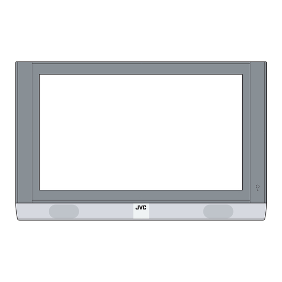
Quick Setup TV/Receiver NOTE: Before you connect your receiver to another device, please refer to the proper diagrams for your specific TV and remote. Display Front Refer to the pages in parentheses for details. Remote control sensor Power lamp (page 17) MENU button (pages 34) INPUT button (page 56) -
Page 138: Tv Remote Control
Quick Setup TV Remote Control TV CATV VCR DVD ASPECT MULTI SCREEN SPLIT INDEX FREEZE SWAP SELECT INPUT 1 INPUT 2 INPUT 3 RETURN+ INPUT 4 100+ THEATER NATURAL VIDEO DIGITAL-IN CINEMA STATUS D-IN SLEEP TIMER DISPLAY SOUND LIGHT MUTING C.C. -
Page 139: Getting Started
Quick Setup Getting Started Getting Started These quick setup pages will provide you, in four easy steps, with the basic information you need to begin using your new television right away. If you have questions, or for more detailed information on any of these steps, please consult other sections of this manual. -
Page 140: Connecting The Tv And Receiver
Quick Setup Getting Started Connecting the TV and Use the supplied power cord which best suits the area in which you live. receiver Power cord Back of the TV AC INLET Use the supplied system cable to connect the TV to the receiver. AC INLET The two connectors are of different shapes. -
Page 141: The Remote Control
The right and left buttons will turn the volume up or down. These buttons are also marked with four arrows and are used with JVC’s onscreen menu system. To use the onscreen menus, press the M button. -
Page 142: Basic Operation
Quick Setup Getting Started Basic Operation Turn the television on and off by pressing the P button at the top right OWER corner of the remote. If this is the first time you are turning on the TV, the interactive plug-in menu appears. •... -
Page 143: Connections
Quick Setup Connections Step 3 – Connecting Your Devices To make these connections, you will use plugs like the ones illustrated below. Coaxial Cables Component Cables Ferrite core (accessory) Composite Cables Audio Cables Used to connect audio/video devices like VCRs, DVD Used to connect an external players, stereo amplifiers, game antenna or cable TV system... - Page 144 Quick Setup Connections Diagram #1 Note: • If you do not have a cable box, connect the cable wire from the wall outlet into the back of the receiver. Diagram #2 Notes: • Use the S-Video connection if possible for superior picture quality. •...
- Page 145 Quick Setup Connections Notes: • Green, blue and red are the most common colors for DVD cables. Some models may vary colors. Please consult the user’s manual for your DVD player for more information. • Be careful not to confuse the red DVD cable with the red audio cable. It is best to complete one set of connections (DVD or audio output) before starting the other to avoid accidentally switching the cables.
-
Page 146: Connecting To Jvc Av Compu Link
AV compu link, the VCR or DVD player sends a signal to the television telling it to turn on and switch to the proper video input. • The AV compu link cable may be included with the JVC AV compu link unit you wish to connect. If it is not, contact JVC Parts Department at (800)-882-2345, or www.jvcservice.com for part # EWP 805-012. -
Page 147: Connecting To A Camcorder
Quick Setup Connections Connecting to a Camcorder You may connect a camcorder, game console or other equipment to your television by using the front input jacks (Input 4) located under the front panel door. To access, pull on the door to open it. - Page 148 Quick Setup Connections Connecting to a Digital TV Receiver w/HDCP By inputting a high bandwidth digital content protection high definition picture source to the digital-in terminal of this television, high-definition pictures can be displayed on the screen in their digital form. (This terminal is for use in the future when high bandwidth digital content protection DTV decoders and DVD players and D-VHS are put on the market.) After the connections have been made,...
- Page 149 Quick Setup Connections Connecting to an AV Receiver using your television’s V1 Smart Input By connecting your AV Receiver to your television's V1 smart Input, you can watch picture sources from many diffeent devices, without having to change or use the other input connections on your TV.
-
Page 150: Plug-In Menu
We recommend you complete the interactive plug-in items before you start using your television. Language After the “JVC INTERACTIVE PLUG IN MENU” has been displayed, the TV automatically switches to the LANGUAGE settings. You can choose to view your onscreen menus in three languages: English, French (Français) or Spanish (Español). -
Page 151: Auto Clock Set
Quick Setup Plug-In Menu Auto Clock Set Before you use any of your TV’s timer functions, you must first set the clock. You may precisely set your clock using the XDS time signal broadcast by most public broadcasting stations. If you do not have this in your area, you will have to set the clock manually. - Page 152 You can now begin watching your television, or you can continue on in this guide for more information on programming your remote control, or using the JVC onscreen menu system to customize your television viewing experience. Notes: •...
-
Page 153: Remote Programming
Remote Programming Setting the CATV, VCR and DVD Codes You can program your remote to operate your cable box, satellite receiver, VCR or DVD player by using the instructions and codes listed below. If the equipment does not respond to any of the codes listed below or to the code search function, use the remote control supplied by the manufacturer. -
Page 154: Vcr Codes
Remote Programming VCR Codes The remote control is programmed with VCR codes for power on/off, play, stop, fast-forward, rewind, pause, record, channel up/down operation. 1) Find the VCR brand from the list of codes shown below. 2) Slide the first 2-way selector switch to “TV” and the other 2-way selector switch to “VCR”. 3) Press and hold down the D button, then enter the first code number listed with the ISPLAY... -
Page 155: Dvd Codes
Remote Programming DVD Codes The remote control is programmed with DVD codes for power on/off, play, stop, fast-forward, rewind, previous/next chapter, tray open/close, and still/pause operation. 1) Find the DVD player brand from the list of codes shown below. 2) Slide the first 2-way selector switch to “TV” and the other 2-way selector switch to “DVD”. 3) Press and hold down the D button, then enter the first code number listed with the ISPLAY... -
Page 156: Search Codes
Remote Programming Search Codes Cable/Satellite Search Codes Function 1) Slide the first 2-Way Mode Selector switch to CATV. 2) Press and hold down the P button, then press the R +/TV button for more than OWER ETURN three seconds. 3) Release the R +/TV button, then release the P button. -
Page 157: Onscreen Menus
Onscreen Menus Using the Guide Certain symbols are used throughout this guide to help you learn about the features of your new television. The ones you will see most frequently are: Up and Down arrows mean press the C + or C –... -
Page 158: The Onscreen Menu System
Onscreen Menus The Onscreen Menu System Your television comes with JVC’s onscreen menu system. The onscreen menus let you make adjustments to your television’s operation simply and quickly. Examples of the onscreen menus are shown on the next page. Detailed explanations on using each menu follow later in this guide. - Page 159 Onscreen Menus Press the M button INITIAL SETUP 03 INITIAL SETUP 04 PICTURE ADJUST 01 INITIAL SETUP 02 PICTURE ADJUST 02 INITIAL SETUP 01 SOUND ADJUST CLOCK/TIMERS Notes: • The DIGITAL-IN menu can only be displayed when a 480p picture signal is input to the digital-in terminal and the picture is being displayed on the screen.
-
Page 160: Initial Setup
Initial Setup Auto Tuner Setup The auto tuner setup function is described on page 27 as the interactive plug-in menu. If you need to run the auto tuner setup again, follow the steps below. Press the M button To AUTO TUNER SETUP To operate To choose CABLE or AIR Press the O... -
Page 161: V-Chip
Initial Setup Channel Guard Message When a viewer attempts to watch a guarded channel, the following message appears: To watch a channel that you have locked, enter the Lock Code using the 10 key pad. If the wrong code is entered, the message “INVALID LOCK CODE!” will flash on the screen. The channel cannot be accessed until the correct THIS CHANNEL IS LOCKED BY code is entered. - Page 162 Initial Setup Unrated Programs Unrated programming refers to any programming which does not contain a rating signal. Programming on television stations which do not broadcast rating signals will be placed in the “Unrated Programming” category. Examples of Unrated programs: • Emergency Bulletins •...
- Page 163 Initial Setup US V-Chip Ratings U.S. PARENTAL RATING SYSTEMS Programs with the following ratings are appropriate for children. ❒ TV Y is Appropriate for All Children Programs are created for very young viewers and should be suitable for all ages, including children ages 2 - 6.
- Page 164 Initial Setup Setting US V-Chip Ratings Press the M button To V-CHIP To operate (The lock icon appears) Press Z to access the V-Chip menu To turn V-Chip ON or OFF To move to SET US TV RATINGS Directions to set US V-Chip Ratings Line up the cursor in the column (TV PG, TV G, etc.) with the content row (V/FV, S, etc.) and press the to move the cursor to the correct location.
- Page 165 Initial Setup Movies Ratings ❒ NR – Not Rated This is a film which has no rating. In many cases these films were imported from countries which do not use the MPAA ratings system. Other NR films may be from amateur producers who didn’t intend to have their film widely released.
- Page 166 Initial Setup Canadian V-Chip Ratings ❒ E – Exempt Exempt programming includes: news, sports, documentaries and other information programming, talk shows, music videos, and variety programming. ❒ C – Programming Intended for Children Violence Guidelines: There will be no realistic scenes of violence. Depictions of aggressive behavior will be infrequent and limited to portrayals that are clearly imaginary, comedic or unrealistic in nature.
-
Page 167: Set Lock Code
Initial Setup Set Lock Code Channel guard and V-Chip settings are protected by a four-digit lock code. Your TV comes pre-set with a lock code of “0000”. You may change the code to any four-digit number you wish. To change the lock code, follow the steps below. Press the M button To SET LOCK CODE... -
Page 168: Auto Demo
Initial Setup Auto Demo This function lets you preview the many different viewing modes of your TV. It will cycle through “index”, “split demo”, “freeze”, all of the different “aspect” ratios and all of the different “video status” modes. Press the M button To AUTO DEMO To turn AUTO DEMO ON or OFF... -
Page 169: Digital-In
Initial Setup Digital-In The DIGITAL-IN option can only be displayed in the INITIAL SETUP menu when a 480p picture signal is being input to the DIGITAL-IN terminal. This option adjusts the position when a 480p picture signal is being displayed on the screen. There are two types of 480p picture signals: 640x480 and 720x480. -
Page 170: Audio Out
Initial Setup Audio Out If your television is connected to an external speaker source, audio out gives you the option of controlling the volume level with your TV’s remote control. Press the M button To AUDIO OUT To VARI or FIX Press the M button when finished VARI: Lets you adjust the volume of the external speakers... -
Page 171: Closed Caption
Initial Setup Closed Caption Many broadcasts now include an onscreen display of dialog called closed captions. Some broadcasts may also include displays of additional information in text form. Your television can access and display this information using the closed caption feature. To activate the closed caption feature, follow the steps below. -
Page 172: Front Panel Lock
Initial Setup Front Panel Lock This allows you to lock the keys on the front of the TV, so that a child may not accidentally change your viewing preferences. Press the M button To FRONT PANEL LOCK To turn ON or OFF Press the M button when finished You can turn off this feature in the following ways:... -
Page 173: Auto Shut Off
Initial Setup Auto Shut Off This function automatically shuts off your TV when there is no signal from the channel the TV is on. Press the M button To AUTO SHUT OFF To turn ON or OFF Press the M button when finished •... -
Page 174: Picture Adjust
Picture Adjust Picture Settings These settings allow you to change and adjust the way the picture appears on your television. TINT Tint allows you to adjust the levels of red and green in your TV picture. COLOR The color function lets you make all the colors in the TV picture appear either more vivid or subtle. -
Page 175: Digital Noise Clear
Picture Adjust Digital Noise Clear With digital noise clear, this helps take our static or noise from a channel that may not be coming in clearly. Press the M button To DIG. NOISE CLEAR To enter To select the mode “LOW”, “HIGH” or “OFF” Press the M button when finished Color Management... -
Page 176: Sound Adjust
Sound Adjust Sound Settings These settings allow you to change and adjust the way the picture appears on your television. BASS – You can increase or decrease the level of low-frequency sound in the TV’s audio with the bass adjustment. TREBLE –... -
Page 177: Clock/Timers
Clock/Timers Set Clock The set clock function is described on page 26 as the interactive plug-in menu. You can choose to set the clock automatically, or manually. If you need to set the clock again, follow the steps below. Press the M button To SET CLOCK To operate... -
Page 178: On/Off Timer
Clock/Timers On/Off Timer The on/off timer lets you program your television to turn itself on or off. You can use it as an alarm to wake up, to help you remember important programs, or as a decoy when you’re not home. -
Page 179: Button Functions
Button Functions Multi Screen Function Your television has two kinds of screen: SPLIT (2 channels) and INDEX (12 channels). Note: After you press any multiscreen button, if you press the menu button, only the picture adjust screen will appear. Split Activate the split-screen option by pressing S on the remote control. -
Page 180: Index
Button Functions Index This allows you to quickly look at up to 12 channels at a time so that you can decide which one to watch. Notes: • Only RF input signal will be displayed. • You can watch the channel added in channel summary. See page 35. Freeze Pressing the F button causes the screen to change to the split-screen display with the... -
Page 181: Power
Button Functions Power Turns the TV on or off. Press the P button OWER Number Buttons - 10Key Pad Use the number buttons on the remote control to move directly to a specific channel. For example, to move to channel 7: 0 (Zero) 7 (Seven) 100+ Button... -
Page 182: Return +/Tv
Button Functions Return +/TV The return+/TV button has three functions: Return - Returns to the channel viewed just before the channel currently onscreen. Return+ - Lets you program a specific channel to return to while scanning through the channels using the CH+ and CH– buttons. TV - Returns to the TV mode. -
Page 183: Muting
Button Functions Muting The M button instantly turns the volume down completely when you press it. Press UTING and the volume level will instantly go to zero. To restore the volume to its previous UTING level, press M again. UTING Video Status ideo status button gives you a choice of four TV picture display settings, including a display of your own preferences. -
Page 184: Sleep Timer
Button Functions Sleep Timer The Sleep Timer can turn the TV off for you after you fall asleep. Program it to work in intervals of 15 minutes, for a total time of up to 180 minutes. Press the S button LEEP IMER Sleep Timer Message... -
Page 185: Aspect
Button Functions Aspect This feature will help you adjust the picture you are watching to give you the best possible picture quality. Aspect Ratios PANORAMA - With this ratio a normal REGULAR - The regular ratio is used 4:3 aspect picture is stretched to fit the when you want to watch a 4:3 broadcast dimensions of the 16:9 aspect screen. -
Page 186: Menu
• See page 46 when you set the caption/text mode. Menu The M button allows you to access JVC’s onscreen menu system. Press M to activate the onscreen menu system. • See individual topics like “Sound Adjust” for specific information on using menus. -
Page 187: Tv/Catv Slide Switch
VCR, please see the code chart and instructions on page 29. • The remote is preset with the code 000 to control JVC-brand DVD players. For any other manufacturer’s brand DVD player, please see the code chart and instructions on page 30. -
Page 188: Troubleshooting
Troubleshooting Refer to the table below to check the condition. If you think that there is a problem, contact the JVC Service Center where you purchased the television. PROBLEMS CHECK - Check for a blown fuse or circuit breaker or a power outage. - Page 189 Troubleshooting PROBLEMS CHECK There are double A building or passing airplane can reflec the original signal and produce a picures (ghosts) second, slightly delayed one. Adjust your antenna position. • Your antenna may be damaged, disconnected or turned. Picture is snowy •...
-
Page 190: Warnings
Warnings Caring for the Cabinet Normally, light dusting with a soft, non-scratching duster will keep your TV clean. If you wish to wipe down the television, first unplug it. Then wipe gently with a soft cloth, slightly moistened with water. You can add a few drops of mild liquid detergent to the water to help remove spots of oily dirt. -
Page 191: Warranty
Commonwealth of Puerto Rico. WHAT WE WILL DO: If this product is found to be defective within the warranty period, JVC will repair or replace defective parts at no charge to the original owner. Such repair and replacement services shall be rendered during regular business hours by JVC authorized service centers. - Page 192 THE DURATION OF ANY IMPLIED WARRANTIES, INCLUDING THE IMPLIED WARRANTY OF MERCHANTABILTY, IS LIMITED TO THE DURATION OF THE EXPRESS WARRANTY HEREIN. JVC SHALL NOT BE LIABLE FOR THE LOSS OF USE OF THE PRODUCT, INCONVENIENCE, OR ANY OTHER DAMAGES, WHETHER DIRECT, INCIDENTAL OR CONSEQUENTIAL...
-
Page 193: Authorized Service Centers
To prevent electrical shock, do not open the cabinet. There are no user serviceable parts inside. Please refer to qualified service personnel for repairs. Accessories To purchase accessories for your JVC product, please call toll free:1 (800) 882-2345 or on the web at www.JVC.com... -
Page 194: Specifications
Specifications MODEL PD-42WX84 Type Plasma Display NTSC, BTSC System (Multi-Channel Sound) Reception Format 1080i DTV digital broadcast ready VHF 2 to 13, UHT 14 to 69 Sub, Mid, Super, Hyper et Ultra bands Reception Range (180 channel frequency synthesizer system) Power Source AC 120V, 60Hz TV : 365W... - Page 195 Notes...
- Page 196 Notes...
- Page 197 JVC COMPANY OF AMERICA JVC CANADA, INC. Division of JVC Americas Corp. 21 Finchdene Square 1700 Valley Road Scarborough, Ontario Wayne, New Jersey, 07470 Canada, M1X 1A7...
Need help?
Do you have a question about the PD-42WX84SJ and is the answer not in the manual?
Questions and answers