Chapters
Table of Contents

Related Manuals for Grizzly G0640X


Summary of Contents for Grizzly G0640X
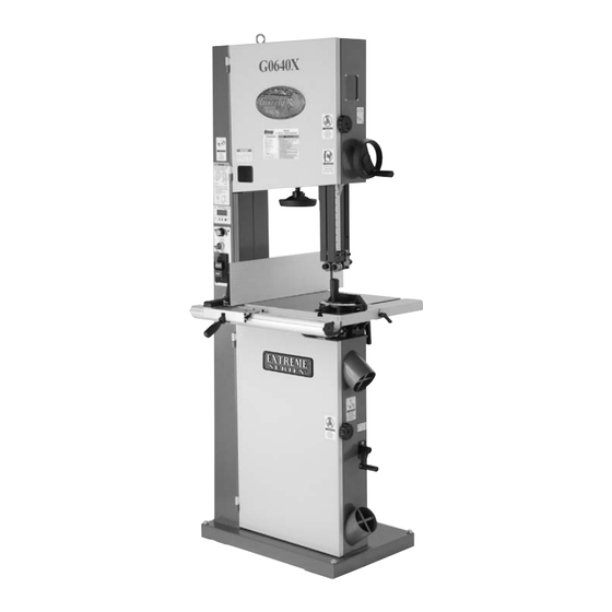
- Page 1 MODEL G0640X 17" WOOD/METAL BANDSAW OWNER'S MANUAL (For models manufactured since 1/09) WARNING: NO PORTION OF THIS MANUAL MAY BE REPRODUCED IN ANY SHAPE OR FORM WITHOUT THE WRITTEN APPROVAL OF GRIZZLY INDUSTRIAL, INC.
- Page 2 This manual provides critical safety instructions on the proper setup, operation, maintenance, and service of this machine/tool. Save this document, refer to it often, and use it to instruct other operators. Failure to read, understand and follow the instructions in this manual may result in fire or serious personal injury—including amputation, electrocution, or death.
-
Page 3: Table Of Contents
Table of Contents INTRODUCTION ..........3 SECTION 4: OPERATIONS ......27 SECTION 1: SAFETY ........7 SECTION 2: POWER SUPPLY ...... 10 SECTION 3: SETUP ........12 SECTION 5: WOOD CUTTING ...... 34 SECTION 6: METAL CUTTING ...... 38 SECTION 7: ACCESSORIES ......41... - Page 4 SECTION 8: MAINTENANCE ......43 SECTION 8: WIRING ........54 SECTION 9: PARTS ........56 WARRANTY & RETURNS ......65 SECTION 9: SERVICE ........46...
-
Page 5: Introduction
INTRODUCTION Foreword Functional Overview www.grizzly.com Contact Info... - Page 6 Identification...
-
Page 7: Machine Data Sheet
Machine Data Sheet Customer Service #: (570) 546-9663 · To Order Call: (800) 523-4777 · Fax #: (800) 438-5901 Weight................................378 lbs. Width (side-to-side) x Depth (front-to-back) x Height................32 x 32 x 73 in. Footprint (Length x Width)........................27 x 17-3/4 in. Type.............................. - Page 8 Table........................Precision Ground Cast Iron Upper Wheel....................... Fully-Balanced Cast Iron Lower Wheel....................... Fully-Balanced Cast Iron Tire................................Rubber Body................................Steel Base................................Steel Wheel Cover............................... Steel Paint............................. Power Coated Wheel Size..............................17 in. Blade Guides Upper........................Ball Bearing Blade Guides Lower........................Ball Bearing Mobile Base............................
-
Page 9: Section 1: Safety
SECTION 1: SAFETY For Your Own Safety, Read Instruction Manual Before Operating This Machine The purpose of safety symbols is to attract your attention to possible hazardous conditions. This manual uses a series of symbols and signal words intended to convey the level of impor- tance of the safety messages. - Page 10 WEARING PROPER APPAREL. FORCING MACHINERY. NEVER STAND ON MACHINE. HAZARDOUS DUST. STABLE MACHINE. USE RECOMMENDED ACCESSORIES. HEARING PROTECTION. UNATTENDED OPERATION. REMOVE ADJUSTING TOOLS. MAINTAIN WITH CARE. INTENDED USAGE. CHECK DAMAGED PARTS. AWKWARD POSITIONS. MAINTAIN POWER CORDS. CHILDREN & BYSTANDERS. GUARDS & COVERS. EXPERIENCING DIFFICULTIES.
-
Page 11: Additional Safety For Bandsaws
Additional Safety for Bandsaws BLADE CONDITION. CUTTING TECHNIQUES. BLADE REPLACEMENT. HAND PLACEMENT. SMALL WORKPIECE HANDLING. FEED RATE. BLADE SPEED. UNSTABLE WORKPIECES. WORKPIECE SUPPORT. BLADE SUPPORT. BLADE CONTROL. UPPER BLADE GUIDE SUPPORT. DUST COLLECTION. WOOD/METAL CONVERSION. -
Page 12: Section 2: Power Supply
SECTION 2: POWER SUPPLY Availability Circuit Requirements for 220V Nominal Voltage ......220V/240V Cycle ............60 Hz Phase ........... Single-Phase Power Supply Circuit ......15 Amps Plug/Receptacle ......NEMA 6-15 Electrocution, fire, equipment damage may occur if machine is not correctly grounded and connected to the power supply. -
Page 13: Figure
Grounding Instructions GROUNDED 6-15 RECEPTACLE Extension Cords 6-15 PLUG Figure 1. Serious injury could occur if you connect the machine to power before completing the setup process. DO NOT connect to power Minimum Gauge Size ......14 AWG until instructed later in this manual. Maximum Length (Shorter is Better)..50 ft. -
Page 14: Section 3: Setup
SECTION 3: SETUP Items Needed for Setup This machine presents serious injury hazards to untrained users. Read through this entire manu- al to become familiar with the controls and opera- tions before starting the machine! Description Wear safety glasses dur- ing the entire set up pro- cess! This is an extremely... -
Page 15: Figure
Inventory Main Components: (Figure 2 & 3) Figure 2. Fasteners (and where used): Figure 3. NOTICE If you cannot find an item on this list, care- fully check the machine and the packaging materials. Some of these items may be pre- installed for shipping or become misplaced during unpacking. -
Page 16: Site Considerations
Cleanup Site Considerations Floor Load Machine Data Sheet Placement Location Figure 4 Before cleaning, gather the following: Basic steps for removing rust preventative: Figure 4. Children and visitors may be seriously injured if unsuper- vised. Lock all entrances to the shop when you are away. Steps 2–3 DO NOT allow unsupervised children or visitors in your... - Page 17 Moving & Placing Mounting Bandsaw Figure 6 HEAVY LIFT! Straining or crushing injury may occur from improperly lifting machine or some of its parts. To reduce this risk, get help from other people and use a fork lift (or other lifting equipment) rated for weight of this machine.
- Page 18 Assembly Figure 10 To assemble the bandsaw: Figure 8 Note: The positive stop bolt acts as a table stop, which makes it easy to bring the table back to 90° after tilting it. Figure 10. Adjusting Blade Guides Page 22 The saw blade is very sharp and can easily cut bare hands.
- Page 19 Figure 12 Note: Keep the upper and lower blade guides adjusted away from the blade until the blade tracking and tension have been adjusting during later steps. Figure 12. Figure 11 Figure 13 Figure 13. Figure 11. Figure 11...
- Page 20 Figure 14 Step 23 Note: After adhering the scale, you can adjust the position of the front rail slightly in either direction to increase the accuracy. This saw creates substantial amounts of fine dust while operating. Failure to use a vacuum system can result in respiratory illness.
-
Page 21: Figure
Blade Tracking Serious personal injury can occur if the machine starts while your hand is touching the bandsaw wheel during tracking adjustments. Disconnect power from the bandsaw Figure 17. before performing blade tracking adjustments. The cast iron spokes may have sharp edges and the blade teeth may extend beyond the edge of the wheel, creating a laceration haz- ard. -
Page 22: Figure
Figure 19 To test run the machine: Figure 19. Test Run NOTICE Figure 20) Changes in the blade tension may change the blade tracking. Test Run Figure 20. Troubleshooting Page 46... -
Page 23: Blade Tensioning
Blade Tensioning Blade Tracking Page To tension the bandsaw blade: Test Run Note: This procedure will NOT work if the blade guides are close to the blade. Note: The power key switch is provided to restrict unauthorized users from operating the bandsaw. - Page 24 Adjusting Blade Guides To adjust the upper and lower blade guides: Figure 22. NOTICE Make sure that the blade teeth will not con- Figure 21 tact the guide bearings when the blade is against the rear support bearing during the cut or the blade teeth will be ruined.
-
Page 25: Adjusting Support Bearings
Adjusting Support Bearings Figure 24 NOTICE Whenever changing a blade or adjusting ten- sion and tracking, the upper and lower blade support bearings and blade guide bearings must be properly adjusted before cutting operations. Figure 24. To adjust the support bearings: Figure 23 Figure 24 Figure 25... - Page 26 Note: For a quick gauge, fold a dollar bill in half twice (four thicknesses of a dollar bill is approxi- mately 0.016") and place it between the support bearing and the blade as shown in Figure 26 Note: The table must be re-aligned with the blade if the trunnion assembly is moved.
- Page 27 Aligning Table To align the table so the miter slot is parallel Figure 28 to the bandsaw blade: Note: Make sure the straightedge fits between the teeth so the tooth set does not skew it. Figure 28. Ensure that the bolt does not turn by Figure 29 holding it with another wrench while tighten- ing the hex nut.
-
Page 28: Aligning Fence
Aligning Fence Miter Gauge To calibrate the miter gauge: To check/align the fence parallel with the miter slot: Figure 31 Step 2 Figure 30 Figure 31. Figure 30. Note: Sometimes the tightening procedure can affect the adjustment. NOTICE Adjusting the fence parallel to the miter slot does not guarantee straight cuts. -
Page 29: Section 4: Operations
WE STRONGLY RECOMMEND that you read books, trade magazines, or get formal training before beginning any projects. Regardless of the content in this section, Grizzly Industrial will not be held liable for accidents caused by lack of training. -
Page 30: Table Tilt
Quick-Release Blade Table Tilt Tension Personal injury or death can occur if the bandsaw starts during table adjust- ment. Disconnect power from the bandsaw before performing table adjust- ments. Figure 33 To tilt the table: Figure 34 Figure 33. Page 21 Figure 34. -
Page 31: Blade Terminology
Blade Terminology Blade Selection Page 39 Blade Terminology Blade Length Model Blade Length Blade Width Figure 35. A. Kerf: Model Blade Width Range B. Tooth Set: Curve Cutting: C. Gauge: D. Blade Width: Blade Width Radius ⁄ " ........⁄ "... - Page 32 Tooth Style Tooth Set Figure 37 Figure 36 Figure 37. Alternate: Figure 36. Standard: Wavy: Raker: Skip: Tooth Pitch Hook: Variable Pitch:...
-
Page 33: Blade Breakage
Blade Breakage Blade Care & Break-In Blade Care The most common causes of blade breakage are: Blade Break-In To properly break-in a new blade: Note: We strongly recommend using mild steel if cutting metal during the break-in phase. Chip Inspection Chart Page 40... -
Page 34: Blade Changes
To replace a blade: Blade Changes Note: If the teeth will not point downward in Always disconnect power any orientation, the blade is inside-out. Put to the machine when on heavy gloves, remove the blade, and twist changing blades. Failure it right side-out. -
Page 35: Blade Speed
Blade Speed Figure 40. Figure 41 Note: If one belt is used more than the other belt, it will stretch slightly under normal condi- tions. This means that one belt may be looser than then other when both belts are installed. This is normal. -
Page 36: Section 5: Wood Cutting
SECTION 5: WOOD CUTTING Workpiece Cutting Tips Inspection Before cutting wood, get in the habit of inspecting all workpieces for the following: Foreign Objects: Large/Loose Knots: Wet or "Green" Stock: Excessive Warping: Minor Warping:... - Page 37 Ripping Crosscutting To make a rip cut: To make a 90° crosscut: Figure 42 Note: If you are cutting narrow pieces, use a push stick to protect your fingers. Figure 43 Figure 42. Figure 43.
- Page 38 To resaw a workpiece: Resawing Figure 44 Note: The blade must also be sharp and clean. NOTICE The scale on the front rail will NOT be accu- rate when using the resaw fence. Figure 44 Figure 44. When resawing thin pieces, a wandering blade (blade lead) can tear through the sur- face of the workpiece, exposing your hands to the blade teeth.
- Page 39 Stacked Cuts Cutting Curves To complete a stacked cut: Cutting Circles Figure 46 Figure 45 Figure 45. Figure 46.
-
Page 40: Section 6: Metal Cutting
SECTION 6: METAL CUTTING Magnesium: Workpiece Inspection Cutting Tips Before cutting, inspect the material for any of the following conditions and take the neces- sary precautions: Small or Thin Workpieces: Round/Unstable Workpieces: Material Hardness: Tanks, Cylinders, Containers, Valves, Etc: Page... - Page 41 Choosing Blades Figure 47 and Speeds To select the correct blade TPI: Figure 47.
-
Page 42: Metal Chip Inspection Chart
Metal Chip Inspection Chart Chip Chip Chip Blade Feed Additional Appearance Description Color Speed Pressure Actions Good Good Good Good Good Figure 48. -
Page 43: Section 7: Accessories
⁄ " Carbon Steel Replacement Blades To reduce this risk, only install accessories recommended for this machine by Grizzly. MODEL WIDTH TPI & TYPE NOTICE Refer to our website or latest catalog for additional recommended accessories. - Page 44 D2057A—Heavy-Duty Mobile H2499—Small Half-Mask Respirator Base H3631—Medium Half-Mask Respirator H3632—Large Half-Mask Respirator H3635—Cartridge Filter Pair P100 Figure 50. Basic Eye Protection T20501—Face Shield Crown Protector 4" T20502—Face Shield Crown Protector 7" Figure 52. T20503—Face Shield Window T20452—"Kirova" Anti-Reflective S. Glasses T20451—"Kirova"...
-
Page 45: Section 8: Maintenance
SECTION 8: MAINTENANCE Cleaning Disconnect machine from power before doing maintenance, or serious injury may occur. Schedule Wheel Brush Daily Adjusting Wheel Brush Page 48 Lubrication Tables, Fence, and Miter Gauge Monthly Page 41 Quarterly... - Page 46 Guide Post Gears Blade and Belt Tension Leadscrews Figures 55 & 56 Figure 54 Figure 54. Figure 55. Figure 56.
- Page 47 Table Trunnions Redressing Rubber Tires Figure 57 To redress the rubber tires: Figure 57.
-
Page 48: Section 9: Service
SECTION 9: SERVICE Note: Please gather the serial number and manufacture date of your machine before calling. Troubleshooting Motor & Electrical Page 45... -
Page 49: Cutting Operations
Cutting Operations Page 32 Page 32 Page 25 Page 32 Cutting Tips Page 34 Page 32 Page 51 Page 24 Adjusting Positive Stop Page Page 51 Miscellaneous Blade Speed Page 33 Page 49 Page 45... - Page 50 Replacing V-Belts Adjusting Wheel Brush Figure 59 To replace the V-belts: Figure 58 Figure 59. Tools Needed: To adjust the wheel brush: Figure 58. Blade Speed Page 33...
-
Page 51: Wheel Alignment
Wheel Alignment Components and Hardware Needed: Tools Needed: Figure 60 To check if your wheels are coplanar: Figure 60 Note: For best results, straighten the 2x4 with a jointer before cutting. Figure 60. Coplanarity Gauge Positions Gauge Figure 61 Tracking Knob Wheels Adjustment... - Page 52 Figure 62 Figure 63 Figure 62. Note: The blade may track slightly off-center when the wheels are coplanar. This is natural because the blade will be balanced on the crown of the tire, rather than just in the center of the tire. This will be more noticeable with larger blades.
- Page 53 Shimming Table Blade Lead Figure 65 Figure 64 Figure 65. To correct blade lead: Figure 64. To shim the table: To skew your fence: Aligning Table Page 25...
- Page 54 Adjusting Tension Lever Tools Needed: To adjust the tension lever: To shift the table: Figure Steps 1–4 NOTICE If the table is shifted, the fence will need to be re-aligned, and the blade guides and blade support will need to be re-adjusted. NOTICE Lead adjustments will change when new blades are mounted on the saw.
-
Page 55: Electrical Component Wiring
Electrical Component Wiring Figure 69. Figure 67. Figure 70. Figure 68. Figure 71. -
Page 56: Section 8: Wiring
This information can be found on the main machine label. Wiring Safety Instructions SHOCK HAZARD. WIRE/COMPONENT DAMAGE. MOTOR WIRING. MODIFICATIONS. CAPACITORS/INVERTERS. WIRE CONNECTIONS. CIRCUIT REQUIREMENTS. EXPERIENCING DIFFICULTIES. The photos and diagrams included in this section are best viewed in color. You can view these pages in color at www.grizzly.com. -
Page 57: Wiring Diagram
REWIRE Wiring Diagram READ ELECTRICAL SAFETY ON PAGE 54! -
Page 58: Section 9: Parts
SECTION 9: PARTS Main... -
Page 59: Main Parts List
Main Parts List REF PART # DESCRIPTION REF PART # DESCRIPTION PSS01M SET SCREW M6-1 X 10 P0640X055A UPPER WHEEL COVER ASSEMBLY P0640X003 SPRING BUSHING PB10M HEX BOLT M6-1 X 25 P0640X004 LIFTING EYE BOLT M10-1.5 PW03M FLAT WASHER 6MM P0640X005 MACHINE BODY P0640X058... - Page 60 Main Parts List PART # DESCRIPTION REF PART # DESCRIPTION P0640X103 SWITCH CONNECTOR CORD 20G PB32M HEX BOLT M10-1.5 X 25 P0640X104 BLADE HOOK PSS02M SET SCREW M6-1 X 6 PS38M PHLP HD SCR M4-.7 X 10 P0640X158 BELT TENSION HANDWHEEL P0640X106 MOTOR FAN CONNECTOR CORD 18G PFS11M...
- Page 61 Fence & Blade Guides...
- Page 62 Fence & Blade Guides Parts List PART # DESCRIPTION PART # DESCRIPTION P0640X001 BUSHING P0640X142 SLIDING PLATE PSS26M SET SCREW M5-.8 X 6 PN04M HEX NUT M4-.7 PFH31M FLAT HD SCR M4-.7 X 8 P0640X144 GUIDE POST RACK P0640X121 FENCE ASSEMBLY 590MM P0640X145 GUIDE POST 121-1...
- Page 63 Fence & Blade Guides Parts List PART # DESCRIPTION PART # DESCRIPTION 173-24 P0640X173-24 LEFT BLADE GUARD 173-32 PLN04M LOCK NUT M8-1.25 173-25 P0640X173-25 SUPPORT BEARING SHAFT 173-33 PW06M FLAT WASHER 12MM 173-27 PCAP97M CAP SCREW M5-.8 X 6 173-34 P0640X173-34 TABLE TILT HANDLE 173-28 PS17M PHLP HD SCR M4-.7 X 6 PCAP72M...
- Page 64 MUST maintain the original location and readability of the labels on the machine. If any label is removed or becomes unreadable, REPLACE that label before using the machine again. Contact Grizzly at (800) 523-4777 or www.grizzly.com to order new labels.
-
Page 65: Warranty Card
WARRANTY CARD The following information is given on a voluntary basis. It will be used for marketing purposes to help us develop better products and services. Of course, all information is strictly confidential. Note: We never use names more than 3 times. _____________________________________________________________________ _________________________________________________________________________________ _________________________________________________________________________________... -
Page 67: Warranty & Returns
WARRANTY & RETURNS 1 year... - Page 68 ® Buy Direct and Save with Grizzly – Trusted, Proven and a Great Value! ~Since 1983~ Visit Our Website Today For Current Specials! ORDER 24 HOURS A DAY! 1-800-523-4777...
Need help?
Do you have a question about the G0640X and is the answer not in the manual?
Questions and answers