
Related Manuals for Gamry Interface 1000

Summary of Contents for Gamry Interface 1000
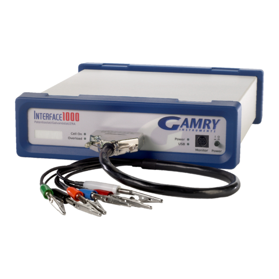
- Page 1 Interface 1000 Potentiostat/Galvanostat/ZRA Operator's Manual Copyright 2012 Gamry Instruments, Inc. Revision 6.0 August 27, 2012 988-00026...
- Page 3 If you have problems in installation or use of a system containing an Interface 1000, it would be helpful if you called from a phone next to your computer, where you can type and read the screen while talking to We will be happy to provide a reasonable level of free support for registered users of the Interface 1000 Potentiostat/Galvanostat/ZRA.
-
Page 4: Limited Warranty
Limited Warranty Gamry Instruments, Inc. warrants to the original user of this product that it shall be free of defects resulting from faulty manufacture of the product or its components for a period of two years from the original shipment date of your purchase. -
Page 5: Disclaimers
Disclaimers Gamry Instruments, Inc. cannot guarantee that the Interface 1000 Potentiostat/Galvanostat/ZRA will work with all computer systems, operating systems, and third party software applications hardware/software. The information in this manual has been carefully checked and is believed to be accurate as of the time of printing. -
Page 7: Table Of Contents
Running the Framework....................3-7 Framework Device Status Bar....................3-8 Gamry Instrument Manager ....................3-9 Authorization Codes and Label ..................3-10 Firmware Update......................3-12 Calibration........................3-14 Separate AC Calibration for Each Interface 1000 Cable Type ........3-14 DC and AC Calibration ..................3-14 The Interface 1000 Personalization Label ................3-16... - Page 8 Introduction to the Interface 1000 Personalization Label........3-16 Label Sheet Provided With Each Interface 1000...........3-16 Label Files on the Gamry Website ................3-16 Procedure to Change a Label ................3-16 Chapter 4 -- Cell Connections .......................4-1 Normal Cell Connections ....................4-1 ZRA Mode Cell Connections .....................4-2 Membrane Cell Connections .....................4-3...
- Page 9 Appendix D – CE Certificate......................12-1 Declaration of Conformity....................12-1 Low Voltage Certificate of Conformance................12-2 RFI Certificate of Conformance ..................12-3 Appendix E -- Heat in Interface 1000 MultEchem Systems..............13-1 Introduction to Device Power Dissipation................13-1 Potentiostat/Galvanostat Power Model ................13-2 Discharging a Battery ......................13-2 Single Interface 1000 ......................13-3...
-
Page 11: Chapter 1 -- Safety Considerations
Category II apparatus, with any "hazardous live voltages" protected by "reinforced insulation". Most of the Interface 1000 circuitry is a voltages low enough to be considered safe. The Interface 1000 contains a limited amount of internal circuitry that is at “hazardous live” voltages as defined in EN 61010 (the standard mentioned above). -
Page 12: Grounding In The Interface 1000
Grounding in the Interface 1000 The circuitry and the metal case of the Interface 1000 are not connected to an earth ground. If they were connected to earth ground, it would compromise the Interface 1000’s ability to make measurements in electrochemical cells that contain earth grounded metal. -
Page 13: Temperature And Ventilation
The Interface 1000 uses forced air-cooling to keep the Interface 1000 components within their operating temperature range. Most of the air needed to cool the Interface 1000 enters the chassis through holes in its bottom plate. Some air also enters the chassis from small slots on the right side of the chassis (as viewed from the front of the instrument). -
Page 14: Defects And Abnormal Stresses
• it has been subjected to environmental stress (corrosive atmosphere, fire, etc.). • Do not use your Interface 1000 or any other apparatus if you think it could be hazardous. Have it checked by qualified service personnel. Environmental Limits Note that there are environmental limit conditions on the storage, shipping and operation of this equipment. -
Page 15: Service
We recommend you avoid using cell phone and other radio frequency equipment in the same room as an Interface 1000. The Interface 1000 circuitry has been tested for operation in high intensity RF fields and has demonstrated little response to those fields. However, there is no guarantee that the electrochemical cell and its connections will not respond to RF fields. -
Page 16: Ce Compliance
The European Community has instituted standards limiting radio frequency interference emitted by electronic devices, setting limits for susceptibility of apparatus to RF energy and transient events, and mandating safety requirements. Gamry Instruments, Inc. has designed and tested the Interface 1000 to comply with these standards. -
Page 17: Chapter 2 -- Introduction
Chapter 4 describes cell cable connections and Chapter 5 describes the Interface 1000’s Front and Rear Panels. Chapter 6 is a description of the electronics circuitry in the Interface 1000. Chapter 7 covers the difficult issues of potentiostat stability and approaches to prevent oscillation. Chapter 8 discusses the realities of low current, high impedance measurements. -
Page 18: Software And Applications
In this type of system, each Interface 1000 is powered by an individual AC Adapter, which in turn can be powered by a multiple output AC power strip. The multiple USB connections for the system can be obtained from an inexpensive commercial USB hub. -
Page 19: Front Panel Personalization
Every Interface 1000 is shipped with its serial number in this label location. More user friendly labels can also be displayed, such as Pstat1, Pstat2, Pstat3. Whimsical names such as "Rusty Dog" can also be displayed in this area. -
Page 21: Chapter 3 -- Installation
Power Switch Initial Visual Inspection After you remove your Interface 1000 from its shipping carton, you should check it for any signs of shipping damage. If any damage is noted, please notify Gamry Instruments, Inc. and the shipping carrier immediately. -
Page 22: Physical Location
Chapter 3 -- Installation--Physical Location Physical Location You normally locate your Interface 1000 on a flat workbench surface. You will want to have access to the rear of the instrument because some cable connections are made from the rear. The Interface 1000 is generally operated in a flat position (see Figure 3-1). -
Page 23: Reboot Your Computer After Software Installation
CEE 22 Standard V (IEC 320 C13) female connector on the apparatus end of the cable. This is the same connector used on the US standard line cord supplied with your Interface 1000. -
Page 24: Power Up Test
1000 (see Figure 3 - 1). Watch the Power LED as the Interface 1000 powers up. It will flash slowly a few times, then glow a steady blue. This process could take as long as 15 seconds. The Interface 1000 fan will run at low speed once the power light stops flashing. -
Page 25: Multiple Potentiostat Systems
Cell Cable Installation The Cell Connector is a 25-pin female D connector on the front of the Interface 1000 (see Figure 3 - 1). All Gamry standard cell cables have a 25-pin D-connector on one end and a number of leads terminated with banana plugs on the other. - Page 26 As shown in this Figure, do not choose to let Windows Update find the device driver that you need. The Windows Update web site has no knowledge of the Gamry Instruments Interface 1000. Make sure you select No, not this time. After you select, Next, you should see a screen that looks like this:...
-
Page 27: Running The Framework
Select Install the software automatically, then select Next. These messages will also be seen when an Interface 1000 instrument is moved to a new USB port. In this case, you can still select Install the software automatically, even if you do not have the Gamry Instruments CD. -
Page 28: Framework Device Status Bar
Framework With Three Potentiostats and One Running Test The Interface 1000 (IFC 01004) in this system is shown with a green indicator because it is installed and ready to run. The Reference 600 labeled My Ref600 has a yellow indicator because it is recording the EIS spectrum shown on the screen. -
Page 29: Gamry Instrument Manager
Chapter 3 -- Installation--Gamry Instrument Manager Gamry Instrument Manager You can use Gamry's new Instrument Manager dialog box to make changes to the configuration of your Interface 1000 system. This dialog box is accessed through the Options menu in the Gamry Framework. -
Page 30: Authorization Codes And Label
Authorization Codes and Label If you purchase additional Gamry application software or you need to make a correction to your authorization codes, you can do so using the Windows Device Manager or the Framework Instrument Manager. The Gamry Framework Application Software must be closed before you can use the Device Manager to make changes. - Page 31 Chapter 3 -- Installation--Authorization Codes and Label Figure 3-7 Device Settings Tab This was the Instrument Manager Device Settings dialog box for the second potentiostat in the system described above. You can enter or edit any of the authorization codes or Label for the device by clicking on the appropriate edit box and entering the in formation.
-
Page 32: Firmware Update
Press OK when you are finished. On occasion you may have to change the USB port used to connect the Interface 1000 to your computer. The Windows Device manager will interpret an Interface 1000 on a new USB port as a new Interface 1000. - Page 33 A status bar shows the progress of the update. The USB indicator on the Interface 1000 should also turn red during the procedure. Once the update is successful, press OK and your Interface 1000 will be ready for use.
-
Page 34: Calibration
The standard Interface 1000 calibration calls for an external resistive dummy cell. Your Interface 1000 was shipped with a Universal Dummy Cell 4, which includes a 2 kΩ Ω Ω Ω , 0.05% accurate resistor in the position marked “Calibration”. After calibration, please place this dummy cell in a safe place where you can find it if your unit requires recalibration. - Page 35 Chapter 3 -- Installation--Calibration Figure 4-10 UDC4 With Leads Attached for Calibration 3 - 15...
-
Page 36: The Interface 1000 Personalization Label
The Interface 1000 includes a personalization label that makes each unit visually unique. This allows you to know exactly which potentiostat will be used for each test. By default, each Interface 1000 ships with a label containing the instrument's Serial Number (S/N XXXXX). Other labels are easily placed in the instrument's Personalization Label area. - Page 37 If you are making a custom printed label, edit the Excel file and print a label sheet as described above. If you are using the Gamry supplied label sheet, identify the location on the sheet where the new label is found.
- Page 38 Replace the rubber bezel. Make sure that the foot side of the bezel is toward the bottom of the instrument. You will need to rename the Interface 1000 in the Gamry Framework to match the new label. You can do this using the Framework Options, Instrument... dialog box. In the resulting Dialog Box, select the device you want to rename and then select the Device Settings...
-
Page 39: Chapter 4 -- Cell Connections
The black pin jack is connected on the Interface 1000 end to Floating Ground. This is the circuitry ground for the analog circuits in the Interface 1000. In most cases, this terminal should be left disconnected at the cell end. -
Page 40: Zra Mode Cell Connections
Interface 1000’s Floating Ground to an earth ground. A binding post on the rear panel of the Interface 1000 is provided for this purpose. A water pipe can be suitable sources of earth ground. -
Page 41: Membrane Cell Connections
In practice, A/D noise and offset will create a small potential signal with a value very close to zero. Membrane Cell Connections The Interface 1000 can be used with membrane cells. In this type of cell, a membrane separates two electrolyte solutions. Two reference electrodes are used - one in each electrolyte. Each electrolyte also contains a counter electrode. -
Page 43: Chapter 5 -- Panel Indicators And Connectors
Power Switch The power switch is located on the far right side of the Interface 1000 Front Panel. It is a push-push switch – push once to turn the instrument on and push again to turn the instrument off. The switch’s button latches –... -
Page 44: The Usb Led
The computer has disabled the USB port going to the Interface 1000. • The USB LED will glow a steady green if a valid USB connection has been made and the Interface 1000’s communication processor is receiving power down the USB cable. -
Page 45: Overload Led
Personalization Label Area The right side of the Interface 1000 front panel has a clear area in its plastic overlay. A paper label behind this area allows for a custom appearance. This is especially important when the instrument is in a multiple potentiostat system. -
Page 46: Rear Panel
USB Port The USB port on the rear panel of the Interface 1000 is a Type B connector as defined in Revision 1.1 and 2.0 of the USB Specification. You use a standard, shielded, Type A/B cable to connect this port to a computer’s USB port or a USB hub (preferably an externally powered hub). -
Page 47: User I/O Connector
Sync Port The Sync Port is used when several Interface 1000 instruments need to be operated with a common clock and simultaneous data acquisition. It is an 8-pin mini-DIN connector. Simultaneous operation is only required when several instruments are connected to a single electrochemical cell. -
Page 49: Chapter 6 -- Instrument Circuitry
The following figures are partly schematic diagrams and partly block diagrams. They are intended to show the basic principles of the Interface 1000 without the confusion of the full circuitry details. The complexity of the Interface 1000 can be quite daunting – the Interface 1000 circuit boards contain more than 2000 components connected by almost 5000 circuit nets. - Page 50 Chapter 6 -- Instrument Circuitry--Interface 1000 Schematic/Block Diagrams Figure 6-1 Interface 1000 Potentiostat Board in Potentiostat Mode Notes for Figure 6-1 Only Potentiostat Mode circuitry is shown in this figure. In this mode the voltage difference between the • Reference and Working Sense leads (called Esig) is fed back into the control amplifier.
- Page 51 The high pass filter provides AC coupling to prevent drift in the DDS’s offset getting into the applied signal. In practice, Gamry EIS300 software uses the DDS to apply sine waves with frequencies between 100 Hz to 1 MHz. It uses the Scan DAC to generate sine signals at frequencies below 100 Hz.
- Page 52 Chapter 6 -- Instrument Circuitry--Interface 1000 Schematic/Block Diagrams Figure 6-3 One A/D Signal Chain in the Interface 1000 Notes for Figure 6-3: This diagram shows one of two identical ADC channels. One channel is dedicated to measurement of • the potentiostat’s current signal and the other is used to measure the voltage signal.
- Page 53 • serial bit stream. The UARTs send data at 6 Mbits/second. The Interface 1000 has local non-volatile data storage. This is used to save calibration data and board • revision information. Interface 1000 calibration data is stored in the instrument, not in a data file.
- Page 54 Figure 6-5 Power Conversion Notes for Figure 6-5: Note the ground isolation between the input power and the Interface 1000 circuitry. The Interface 1000 • chassis is connected to the Floating Instrument Ground. Transformers and digital isolators are the only components connected between the grounds.
-
Page 55: Chapter 7 -- Stability In Potentiostat Mode
Whenever you see sharp breaks in the current recorded on the system, you should suspect oscillation. The Interface 1000 has been tested for stability with cell capacitors between 10 pF and 3000 F. In all but its fastest control amp speed setting, it is stable on any capacitor in this range -- as long as the impedance in the reference electrode lead does not exceed 20 kΩ. -
Page 56: Improving Potentiostat Stability
Improving Potentiostat Stability There are a number of things that you can do to improve an unstable or marginally stable Interface 1000 potentiostat/cell system. This list is not in any particular order. Any or all of these steps may help. - Page 57 Chapter 7 -- Stability in Potentiostat Mode--Improving Potentiostat Stability Provide a high frequency shunt around the cell. A small capacitor between the red and white cell • leads allows high frequency feedback to bypass the cell. See Figure 7-2. The capacitor value is generally determined by trial and error.
- Page 58 Chapter 7 -- Stability in Potentiostat Mode--Improving Potentiostat Stability Add resistance to the counter electrode lead. See Figure 7-3. This change lowers the effective • bandwidth of the control amplifier. As a rule of thumb, the resistor should be selected to give one volt of drop at the highest current expected in the test being run.
-
Page 59: Chapter 8 -- Measurement Of Small Signals
To place this current in perspective, 333 fA represents the flow of about 2000000 electrons per second! The small currents measured by the Interface 1000 place demands on the instrument, the cell, the cables and the experimenter. Many of the techniques used in higher current electrochemistry must be modified when used to measure pA currents. -
Page 60: Johnson Noise In Z Cell
Chapter 8 -- Measurement of Small Signals--Measurement System Model and Physical Limitations Figure 8-1 Equivalent Measurement Circuit R shunt C shunt Icell R in C in Unfortunately, technology limits high impedance measurements because: Current measurement circuits always have non-zero input capacitance, i.e. C >... -
Page 61: Finite Input Capacitance
Chapter 8 -- Measurement of Small Signals--Measurement System Model and Physical Limitations 41 µV rms. The peak-to-peak noise is about 5 times the rms noise. Under these conditions, you can make a voltage measurement of ± 10 mV across Z with an error of about ±... -
Page 62: Voltage Noise And Dc Measurements
AC signal by more than a factor of 10. The Interface 1000 uses an input amplifier with an input current of around 1 pA. Other circuit components may also contribute leakage currents. You therefore cannot make absolute current measurements of very low pA currents with the Interface 1000. -
Page 63: Hints For System And Cell Design
Try to avoid AC powered or computerized apparatus within your Faraday shield. Cell Cable Length and Construction The Interface 1000 is shipped with a 60 cm shielded cell cable. We also offer extended length cables and a special cable for low impedance cells as extra cost options. -
Page 64: Lead Placement
Many experiments with the Interface 1000 involve cells with small capacitances, the value of which may be important. In these cases, the capacitance between the Interface 1000 cell leads can result in an error. The Interface 1000 alligator clips can have 10 pF or more of mutual capacitance if they are run alongside each other. -
Page 65: Eis Speed
Interface 1000 cell leads. Floating Operation The Interface 1000 is capable of operation with cells where one of the electrodes or a cell surface is at earth ground. Examples of earth grounded cells include: autoclaves, stress apparatus, pipelines, storage tanks and battleships. -
Page 67: Appendix A -- Interface 1000 Specifications
Appendix A -- Interface 1000 Specifications All specifications are at an ambient temperature of 22 °C, with the Interface 1000 powered using the external power supply shipped with the unit, a standard shielded 60 cm cell cable, and the cell enclosed in a Faraday shield. - Page 68 Appendix A -- Interface 1000 Specifications--Floating Operation Current to Voltage Converter Maximum Full Scale Range 1000 Note 13 Minimum Full Scale Range Note 13 100 (after x100 gain) Voltage across Rm mV at Note 14 full scale Output Voltage (at Monitor and ADC in)
- Page 69 Appendix A -- Interface 1000 Specifications--Floating Operation Potentiostatic Mode Applied Voltage Range volts ± 12 Accuracy Note 18 DC zero offset Gain % setting DC Bias volts ± 8 Scan DAC ranges volts ± 6.4, ± 1.6, ± 0.4 Drift <...
- Page 70 4. Measured with an external function generator connected to the Ext Sig In BNC. 5. The A/D and signal processing chain in the Interface 1000 allows measurement of voltage signals as large as ±13.107 V. The voltage on the Work Sense lead can be as high as ±0.4 V when measuring 1A using a 60 cm cell cable.
- Page 71 21. See Appendix D. 22. Isolation quality has both DC factors and AC factors (predominately at the 600 kHz power supply frequency). Only the DC leakage current is shown here. Consult Gamry technical support for additional information. 23. Excluding external power adapter and any cables supplied with unit.
-
Page 73: Appendix B -- Interface 1000 Cell Connector
Multiple pins assigned to the same signal are connected together on the Interface 1000’s Potentiostat board. If you need to connect this signal outside the Interface 1000, you need a wire connected to any one of the D connector pins. - Page 74 Appendix B -- Interface 1000 Cell Connector--Floating Operation 10 - 2...
-
Page 75: Appendix C -- I/O Connectors
The details of these connectors are described here. User I/O Connector This connector contains a number of signals, used to interface the Interface 1000 to external apparatus. It is the miniature 15 pin female D shaped connector on the rear panel of the Interface 1000. -
Page 76: Monitor Connector
DC pins in the DIN connector are used to detect all cable connections and most importantly detect the Master end of the cable. We ask that you use Gamry supplied cables for all Master - Serf synchronized systems. The cable uses a differential pair that requires controlled impedance making user construction of a cable very difficult. - Page 77 External Signal In External Signal In allows you to add a voltage to the Interface 1000's Signal Generator. It is a 2-wire differential signal with the negative side connected to the Interface 1000 floating ground. This signal will be summed with the other signal generator sources including the Bias DAC, the Scan DAC, and the DDS output.
-
Page 79: Appendix D - Ce Certificate
Manufacturer's Name and Location: Gamry Instruments 734 Louis Drive Warminster, PA 18974 This declaration is for the Gamry Instruments product: Interface 1000 Potentiostat/Galvanostat/ZRA. The declaration is based upon compliance with the following directives: EMC Directive 2004/108/EC Low Voltage Safety Directive 2006/95/EC The declaration is based upon product compliance with the following standards as defined in report number 05965-000 from Ergonomics, Inc. -
Page 80: Low Voltage Certificate Of Conformance
Appendix D – CE Certificate--Low Voltage Certificate of Conformance Low Voltage Certificate of Conformance 12 - 2... -
Page 81: Rfi Certificate Of Conformance
Appendix D – CE Certificate--RFI Certificate of Conformance RFI Certificate of Conformance 12 - 3... -
Page 83: Appendix E -- Heat In Interface 1000 Multechem Systems
Appendix D – CE Certificate--Introduction to Device Power Dissipation Appendix E -- Heat in Interface 1000 MultEchem Systems Introduction to Device Power Dissipation All electronic devices require power to operate. In most cases, this power generates heat within the device. -
Page 84: Potentiostat/Galvanostat Power Model
The variable resistors take different values depending on the potentiostat/galvanostat’s operating conditions. The upper portion of the model describes a fairly constant power draw in the Interface 1000 circuitry. This power comes from the normal operation of the instrument: running its microprocessor, powering its operational amplifiers and D/A and A/D converters, etc. -
Page 85: Single Interface 1000
• If we only have a single battery and its voltage is 5 V, the maximum power dissipation is 37 W. • If the battery stack has a voltage equal to the largest measurable Interface 1000 cell voltage (12 Volts) the maximum power dissipation in the instrument is 44 W. -
Page 87: Comprehensive Index
1-2 ancillary apparatus, 8-8 floating operation, 8-7 authorization code \c chapter, 3-10 fluorescent lights, 8-6 auxiliary electrode, 4-1 Gamry Framework, 2-1 black banana, 4-1 green cell lead, 4-1 blue cell lead, 4-1 ground, 10-1 calibration, 3-14... - Page 88 Comprehensive Index-- User I/O connector, 5-5 operation, 1-4 orange lead, 4-1 ventilation, 1-4, 3-2 oscillation, 7-1 Visual Inspection, 3-1 Overload LED, 5-3 voltage noise, 8-4 over-temperature event, 13-2 Warranty, ii overview, 2-1 WE Shield, 10-1 personalization label, 3-16 white cell lead, 4-1 power brick, 1-1 Windows Update, 3-6 Power Connection, 3-3...
Need help?
Do you have a question about the Interface 1000 and is the answer not in the manual?
Questions and answers