Table of Contents
Advertisement
Quick Links
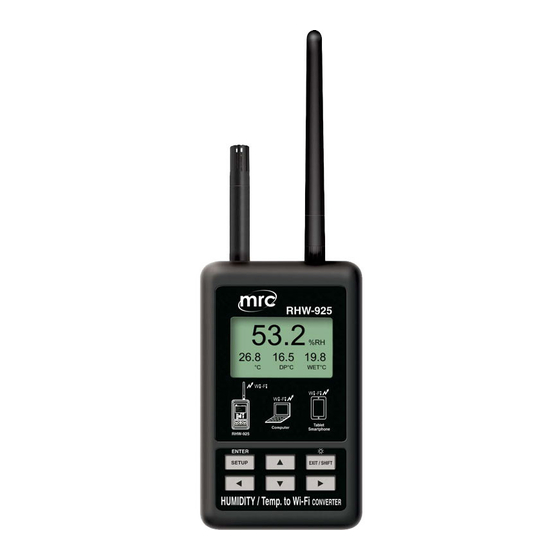
RS232 to WiFi CONVERTER
Model : RHW-925
Your purchase of this
RS232 to WiFi
CONVERTER marks a
step forward for you
into the field of
precision measurement.
Although this Meter is a
complex and delicate
instrument, its durable
structure will allow
many years of use if
proper operating
techniques are
developed. Please read
the following
instructions carefully
and always keep this
manual within easy
reach.
OPERATION MANUAL
PLEASE READ THIS MANUAL CAREFULLY BEFORE OPERATION
Hagavish st. Israel 58817 Tel: 972 3 5595252, Fax: 972 3 5594529
mrc@mrclab.com
MRC.11.17
Advertisement
Table of Contents

Related Manuals for MRC RHW-925


Summary of Contents for MRC RHW-925
- Page 1 RS232 to WiFi CONVERTER Model : RHW-925 Your purchase of this RS232 to WiFi CONVERTER marks a step forward for you into the field of precision measurement. Although this Meter is a complex and delicate instrument, its durable structure will allow...
-
Page 2: Table Of Contents
TABLE OF CONTENTS 1. FEATURES..........................2. SPECIFICATIONS........................3. FRONT PANEL DESCRIPTION............... 4 4. MEASURING PROCEDURE................4-1.The initial startup screen....................4-2.Measuring and setting screens..................4-3.The summary description of keyboard................4-4.Setting Description......................4-5.Set value storage..................... 4-6.Mesurement and WiFi connection................... 4-7.Reply factory setting...................... 4-8.AP Mode....................... -
Page 3: Features
1. FEATURES * Can be temperature and humidity data sent to the desired device through WiFi. the use of smart phones or tablet computers developed by the company's free software to do data collection record APP. * WiFi work mode: Access Point(AP) or Client mode * I/O terminal: 1.DC 9V power input 2.DC 9V power output(power supply for the connecting RS232 meter) -
Page 4: Specifications
2. SPECIFICATIONS Circuit Custom single-chip microprocessor LSI circuit Display LCD Size: 3.2 X 2.4” (60 X 44.4 mm) Dot Matrix backlit LCD (128 X 64 pixels) Wireless * Support IEEE 802.11b / g / n wireless standards * Support the range of frequency : 2.412 to 2.484 GHz. * Support two types of wireless networks: Access Point(AP) and Client * Support multiple security authentication mechanisms :... - Page 5 Accessories * Instruction manual............1PCS included * Hanging unit ( with sticker )......... 1PCS * AC to DC 9V power adapter........1PCS Optional * RS232 cable,UPCB-02. Accessories * Pt 1000 Temp. probe,TP-1000 * USB cable,USB-01. * Data Acquisition software,SW-U801-WIN. * Power interface cable, PWCB-06 2-2.Electrical Specifications (23 ±...
-
Page 6: Front Panel Description
3. FRONT PANEL DESCRIPTION Fig. 1 3-1 DC 9V Power adapter input socket 3-2 DC 9V output socket 3-3 Humidity/Temp. sensor 3-4 Antenna and antenna socket 3-12 System reset button 3-5 Display 3-13 Stand 3-6 SETUP/ENTER KEY 3-14 Hanging holes 3-7 EXIT( ) key button 3-15 Hanging unit ( with sticker ) -
Page 7: Measuring Procedure
4. MEASURING PROCEDURE 4-1.The initial startup screen SCREEN4-1-1 SCREEN4-1-2 4-2.Measuring and setting screens: 1.Measurement screen: SCREEN4-2-1 SCREEN4-2-2 SCREEN4-2-3 SCREEN4-2-4 SCREEN4-2-5 SCREEN4-2-6... -
Page 8: 4-3.The Summary Description Of Keyboard
2.Setting screen: SCREEN4-2-5 SCREEN4-2-6 4-3.The summary description of keyboard: 1.SETUP(Enter) KEY: Setting screen into the select key 2.In the setting mode: 2-1.Press ▲ or ▼ to select the field in the upper and lower beating 2-2.▲ or ▼ > 2 SEC.: The selected field will rapidly beating 2-3.▲... - Page 9 5-1.NetMode: Select AP or Client, the factory setting is Client. A. Enter this option, then press KEY contents into the option, then press ▲ or ▼ KEY to select AP or Client, After determining Press SETUP KEY do confirm the contents, then will return to NetMode directory B.
-
Page 10: 4-5.Set Value Storage
5-7.Gateway: The default setting is 192.168.0.1 A. Press KEY then enter the option contents, then press ▲ or ▼ KEY to select the number, press the SETUP KEY The contents do confirm, then will return to the Gateway directory B.Press ▼ KEY into the Meter CH.option from Gateway 5-8.UNIT: A. -
Page 11: 4-8.Ap Mode
2) CH NO.: In accordance Meter CH NO. To enter 3) Sampling time: minutes as a reference, check after do Logger function (must be set) 4) IP: In accordance with RHW-925 IP as input and must tick (must be set) - Page 12 5) Port: In accordance with RSW-925 Port as input and must tick (must be set) 6) Save file: Select the Logger path to be stored (must be set) 7) Alarm Beeper: After checking the SCREEN4-8-7 to tie the set , when they meet the conditions have an effect 8)Alarm SMS: After checking the SCREEN4-8-7 to tie the set, when meet the conditions will send SMS D.
- Page 13 SCREEN4-8-3 SCREEN4-8-4 SCREEN4-8-5 SCREEN4-8-6 SCREEN4-8-7 SCREEN4-8-8...
-
Page 14: 4-9.Client Mode (Internal Network)
4-10.Client Mode(External network fixed IP): 1.Simple schematic network: Internet Modem IP Router Wireless(AP) 2. The RHW-925 is set to Client mode, the relevant parameters are as follows: 2-1.NetMode: Client 2-2.SSID: RHW-925 2-3.IP: 192.168.0.254 2-4.Port: 200 2-5.Gateway: 192.168.0.1(With a smart phone in the App Store to... - Page 15 3.into the IP Router do parameter settings, the contents of the red box set you can do 4.Execution MeterApp, enter the need of parameters. IP item which required the use of IP Tools software to learn the input...
-
Page 16: 4-11.Client Mode(External Network Floating Ip)
1.Simple schematic network: URL forwarding Internet Modem IP Router Wireless(AP) server 2.The RHW-925 is set to Client mode, the relevant parameters are as follows: 2-1.NetMode: Client 2-2.SSID: RHW-925 2-3.IP: 192.168.0.254 2-4.Port: 200 2-5.Gateway:192.168.0.1(With a smart phone in the App Store to... - Page 17 4.Apply for free transfer to www.noip.com address, the name of the application will be transferred to the address input to the IP Router 5.Execution MeterApp, enter the need of parameters. IP item which required the use of IP Tools software to learn the input...
-
Page 18: 4-12.Ethernet Mode Connecter Network Floating (Intenal Network )
4-12.Ethernet Mode connecter network floating (intenal network ): 1.Simple schematic network: Internet Modem IP Router LAN PORT RHW-925 2.The RHW-925 is set to Client mode, the relevant parameters are as follows: 2-1.IP: 192.168.0.254 2-2.Port: 200 2-3.Gateway: 192.168.0.1 3.RJ485 connecter model as 3-19, Fig1. -
Page 19: 4-15.Ethernet Mode Is Connected Via The Wireless Bridge Network
4-15.Ethernet Mode is connected via the wireless bridge network (External network Floating IP ): 1.Simple schematic network: URL forwarding Internet Modem IP Router Wireless(AP) server Wireless(Bridge) RHW-925 2.The RHW-925 is set to Client mode, the relevant parameters are as follows: 2-1.IP: 192.168.0.254 2-2.Port: 200 2-3.Gateway: 192.168.0.1... - Page 20 3. Enter the IP Router to set parameters,Set the contents of the red box. 4. To www.dlinkddns.com apply for a free address, the application of the address name input to the IP Router. 5. When the Metro App is implemented, the required parameters are entered using the IP Tools software as SCREEN4-8-4、...
-
Page 21: 4-16.Rs232 Function Serial Output
4-16.RS232 Function SERIAL OUTPUT The instrument is provided an 3.5 mm dia. Phone socket ( 3-7, Fig. 1 ) for RS232 computer interface socket. The connector output is a 16 digits data stream which can be utilized to the user's specific application. A RS232 lead with the following connection will be required to link the instrument with the PC or NB USB port or serial port. - Page 22 Each digit indicate the following status : Start Word 1 ~ 9 D12 & D11 Annunciator for Display 01=℃ 02=℉ 04 = %RH Polarity 0 = Positive 1 = Negative Decimal Point(DP), position from right to the left 0 = No DP, 1= 1 DP, 2 = 2 DP, 3 = 3 DP D8 to D1 Display reading, D1 = LSD, D8 = MSD For example :...
Need help?
Do you have a question about the RHW-925 and is the answer not in the manual?
Questions and answers