Table of Contents
Advertisement
Advertisement
Table of Contents

Subscribe to Our Youtube Channel
Related Manuals for JKEXER Turbo 776


Summary of Contents for JKEXER Turbo 776
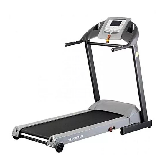
- Page 1 MOTORIZED TREADMILL Turbo 776...
-
Page 2: Table Of Contents
TABLE OF CONTENTS IMPORTANT SAFETY INSTRUCTIONS ..... . P . 1 ELECTRICAL GROUNDING INSTRUCTIONS ....P . 2 CAUTION: BEFORE AND AFTER RUNNING ON THE TREADMILL . -
Page 3: Important Safety Instructions
IMPORTANT SAFETY INSTRUCTIONS Please read the following basic precautions prior to use of the treadmill: * Never operate the treadmill with the air openings blocked. Keep air openings free of lint, hair, and the like. WARNING * This treadmill requires a dedicated circuit as 110V/220V 15/10AMP separately that is not shared by any other electrical appliances . -
Page 4: Electrical Grounding Instructions
* Do not walk or jog barefoot or without shoes . * Do not plug into the same outlet with any * Do not walk or jog in loose shoes or slippers . other electrical appliance while using this Athletic shoes are always recommended treadmill . -
Page 5: Caution: Before And After Running On The Treadmill
CAUTION: BEFORE AND AFTER RUNNING ON THE TREADMILL Before Running: 1. Read the manual first for familiarization of the computer and other important features. 2. Before starting the treadmill, always stand on two side rails on both sides (not on the running belt) as shown on drawing. - Page 6 What to lubricate? Do not lubricate with other than our approved lubricant. Your treadmill comes with one 30ml tube of silicone. For further lubrication, you may order from distributor for our 200ml silicone: • 200ml silicone in one bottle with 35cm applicator •...
-
Page 7: Assembly Parts List
ASSEMBLY PARTS LIST 1. MAIN FRAME ..................... 1 2. FRONT POST ..................... 2 3. METER ......................... 1 4. CROSS BAR ......................1 5. POWER CABLE ....................1 A. BOLT & WASHER ..................2+2 B. BOLT ........................2 C. BOLT & WASHER .................. -
Page 8: Assembly Instructions
ASSEMBLY INSTRUCTIONS Step 1. Well connect the cables from Front Post and Main Frame, then insert Front Post FRONT POST onto Main Frame . No need to put the Bolts yet . MAIN FRAME WARNING FRONT POST CABLE CROSS BAR Step 2: Attach Cross Bar to two inner sides of both Front Post as photo shown, then use Bolt... - Page 9 STEP 3: Use Bolt (C) to fix Front Post to the Main FRONT POST Frame . Then tighten all bolts mentioned on Step 2 . MAIN FRAME Step 4. Remove the Cap on the handlebar, then well connect cables (three cables on right side, and one cable on left side), place them into Handlebar then put the cap into the tube .
-
Page 10: Positioned For Operation
Step 6. Plug in the power cable for operation . POSITIONED FOR OPERATION There are balancers at the front bottom . Adjust these balancers to make sure main frame is stably positioned on the ground for exercise . -
Page 11: Treadmill Operation
TREADMILL OPERATION CAUTION: Before beginning a workout session make sure the safety key is properly placed onto the computer console and the safety clip is securely attached to an article of your clothing . Always start the treadmill while standing on the side rails but not on the running belt . Allow the treadmill to reach a speed of at lease 1 .0 KPH before walking on the running belt . - Page 12 For HRC program (H1, H2, H3) After choosing H1, H2 or H3, Then press ENTER button, default setting age: 30 flashes press INCLINE (or SPEED ) button to set age: 13 ~ 70. For example, you set 35 years old, then press ENTER button, heartbeat 111 appears on pulse window and level 1 flashes.
- Page 13 (incline control) operation: Operation is same as HRC 1 A. Actual heartbeat is lower than preset max. heartbeat: Increase incline 1% per detection. B. Actual heartbeat is higher than preset max. heartbeat: Decrease incline 1% per detection. (speed and incline control) operation: Operation is same as HRC 1 A.
- Page 14 FUNCTION OF BUTTONS 1. Quick Speed buttons There are 8 speed buttons 2, 4, 6, 8, 10, 12, 14, 16KPH 2. SPEED (Fast/Slow) button They are for speed adjustment, setting adjustment and for 12 pre-set program selection. 3. INCLINE (Up/Down) button They are for incline adjustment, setting adjustment and for TARGET, USER and HRC program selection.
- Page 15 INCLINE SPEED LEVEL 2 LEVEL 3 Interval 1 Interval 1 6 .0 KPH 6 .0 KPH 7 .0 KPH 7 .0 KPH Interval 2 Interval 2 7 .0 KPH 8 .0 KPH 10 .0 KPH 7 .0 KPH Interval 3 Interval 3 8 .0 KPH 10 .0 KPH 12 .0 KPH...
- Page 16 SPEED / SPEED / INCLINE INCLINE LEVEL 1 LEVEL 3 3 .0 2 .0 2 .0 2 .0 7 .0 6 .0 6 .0 6 .0 Interval 1 Interval 1 KPH/2% KPH/2% KPH/2% KPH/3% KPH/6% KPH/6% KPH/6% KPH/7% 3 .0 2 .0 2 .0 6 .0...
-
Page 17: Master Power Switch Location
MASTER POWER SWITCH LOCATION To complete shut off power to the treadmill, turn off master power switch and unplug from outlet . ERROR MESSAGE & TROUBLE SHOOTING E1 (Error 1): When the machine starts but computer could not read the signal from sensor for 7 seconds, E1 will be shown on the computer . -
Page 18: How To Fold Up For Storage
HOW TO FOLD UP FOR STORAGE Lift the rear end of the frame to the computer till you hear a "CLICK" sound from cylinder then push and pull it to make sure the frame is fixed . HOW TO FOLD DOWN FOR EXERCISE There is a safety pin on the air-shock . -
Page 19: Aligning The Running Belt
ALIGNING THE RUNNING BELT Ensure the running belt is centered on your treadmill at all times . FIGURE A Running style and Non-level surface are two instances which may cause the belt to drift off center . Minor adjustments to the two bolts at the rear of the treadmill are necessary when the belt has drifted off center . -
Page 20: Cleaning
CLEANING Firstly, make sure the treadmill is off and unplugged from the electrical outlet . To remove dust, use a small vacuum nozzle to carefully vacuum around all visible components . To remove film or dust, use a slightly damp rag with a mild cleaning agent sprayed onto the rag only . Be careful not to immerse any treadmill component with any liquids . -
Page 21: Exploded Drawing
Exploded Drawing... -
Page 22: Parts List
Parts List DESCRIPTION DESCRIPTION DESCRIPTION MAIN FRAME BREAKER MENTAL BUSH (Ø16 x 21.5) BOTTOM STAND SOCKET BUSH (T023) CROSS TUBE POWER SWITCH BOLT (M10 x 30) FRONT POST (L) CENTER BAR SCREW (M4 x 6) FRONT POST (R) SENSOR SCREW (5/32" x 10) FRONT FRAME MAGNET COIL (CE) SCREW (5/32"... - Page 24 2016.01.13...
Need help?
Do you have a question about the Turbo 776 and is the answer not in the manual?
Questions and answers