Sign In
Upload
Manuals
Brands
Sinee Manuals
Inverter
EM100-0R4-1B
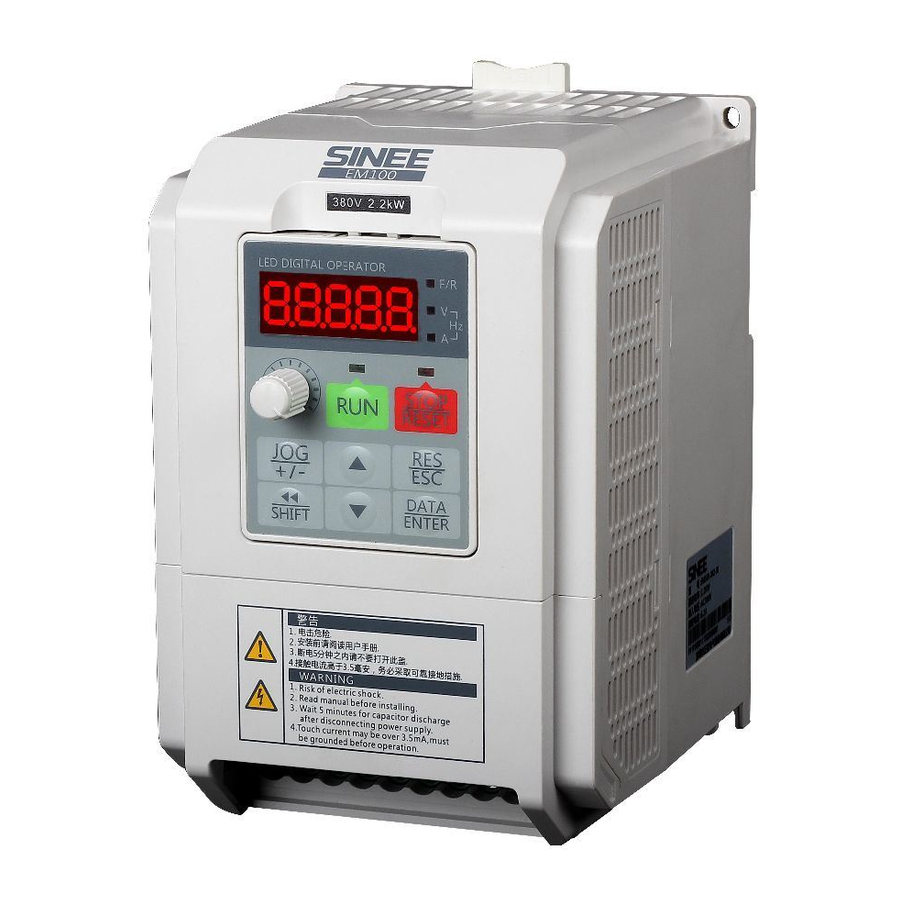
Sinee EM100-0R4-1B Mini Inverter Manuals
Manuals and User Guides for Sinee EM100-0R4-1B Mini Inverter. We have
1
Sinee EM100-0R4-1B Mini Inverter manual available for free PDF download: User Manual
Sinee EM100-0R4-1B User Manual (121 pages)
EM100 series Mini Inverter
Brand:
Sinee
| Category:
Inverter
| Size: 2 MB
Table of Contents
Table of Contents
2
Safety Information
3
Safety Precautions
3
Wiring
4
Before Power-On
4
After Power-On
5
During Operation
5
Safe Maintenance
5
Precautions
6
Motor Insulation Inspection
6
Motor Heat and Noise
6
Lightning Protection
6
Overview
7
Verifying Product
7
Model Numbering Scheme and Nameplate
7
Model Number List
8
Technical Specifications
8
EM100 Outloook
11
Product View
11
Outlook
11
Overall Dimensions
12
Diagram of Overall and Installation Dimensions
12
Keypad Dimensions
13
Dimensions of Keypad Chassis (Accessories) and Mounting Holes
13
Mechanical Installation
14
Installation Site
14
Installation Precautions
14
Installation Direction, Space and Cooling
14
Installation Space of Single EM100
15
Vertical Installation of Multi-EM100
15
Table of Heat Dissipating Capacity (HDC), Mass Airflow(MAF) and Noise of Single EM100
16
Load Shedding Curve
16
Installing with Screws
17
4-Hole Installation
17
3-Hole Installation
18
DIN Rail Installation (DIN Rail Width: 35Mm)
18
Flange Mounting (for the Models with Frame SIZE3&4)
18
Disassembly and Assembly of Keypad
20
Disassembly and Assembly of Terminal Cover
21
Mounting Keypad
22
Wiring/Considerations for Wiring
23
Connection to Peripherals
24
Wiring Main Circuit and Control Circuit
25
Function of Main Circuit
26
Standard Wiring of Main Circuit
27
Wiring Main Circuit on Input Side
27
Installing a Leakage Circuit Breaker
27
Installing an Electromagnetic Contactor
27
Installing an AC Reactor
28
Installing a Surge Absorber
28
Installing a Noise Filter on Power Supply Side
28
Wiring the Output Side of Main Circuit
29
Countermeasures against Inductive Interference
30
Countermeasures against Radio Frequency Interference(RFI)
30
Cable Length between Inverter and Motor
30
Main Circuit Cable
31
Grounding Wiring
31
Wiring Braking Resistor
32
Wiring Control Circuit Terminals
32
Function of Control Circuit Terminals
32
Wiring the Analog Input Terminals
34
Wiring Multi-Function Input Terminals
34
Wiring Multi-Function Output Terminal
34
Wiring Communication Terminal
35
RS485 and Single Inverter Connection
35
RS485 and Multi-Inverter Connection
35
Connecting Inverter to PC/PLC Via RS485/RS232 Converter
35
Size of Control Circuit Cable and Screw
36
Remarks for Wiring Control Circuit
36
Extending Keypad Cable
36
Disassembling the Keypad and Connecting Extension Keypad Wire
37
Wiring Check
37
Keypad Operation
38
Name and Function of each Key on the Keypad
38
Function Code Check and Editing Method
39
Keypad Operation Modes
39
Function Setting
40
Main Menu Selection
40
Selecting Parameter to View Value
40
Sub-Menu Selection
40
Keypad Potentiometer
41
Operation Status Monitoring
41
Parameter Saving and Resetting Procedures
41
Shortcut Key Operation
41
Autotuning Motor Parameter Via Keypad Operation
42
Fault Reset/Monitoring
42
Function of JOG Key
42
Insufficient Operation Conditions
42
Parameter Tables
43
Format of Parameter Tables
43
F00 Group:general Parameters
43
F01Group:motor Parameters
45
F02 Group:input Terminal Parameters
46
F03 Group:output Terminal Parameter
48
F04 Group:start/Stop Control Parameters
49
F05 Group:V/F Control Parameters
49
F06 Group: Auxiliary Function Parameters
50
F07 Group:fault and Protection Function Parameters
52
F08 Group: Preset Speed and PLC Parameters
53
F09 Group: PID Parameters
55
F10 Group: Communication Parameters
55
F11 Group: User Parameters
56
C00 Group:monitoring Parameters
57
E00 Group:fault Monitoring Parameters
58
Parameter Description
59
F00: General Parameters
59
2-Wire Sequence Terminal Control Mode 2
60
3-Wire Terminal Control Mode 1
61
3-Wire Terminal Control Mode 2
62
F00.05 for Selecting Integrated Frequency Setting Modes
63
F00.06 for Selecting Analog Integrated Speed Setting Modes
63
F00.07 Operation Frequency Primary Numeric Setting Value
64
F00.08 Operation Frequency Auxiliary Numeric Setting Value
64
Speed Setting Input Modes
65
Motor Reverse Permission
66
Selecting Motor Status of Switching Forward/Reverse
66
Forward/Reverse Deadband
67
F00.18=0 Fixed Carrier
67
F00.18=1 Random Carrier
67
F00.18=2 Derating of Fixed Carrier
67
Saving Setting Frequency Options
68
F01: Motor Parameters
68
T Equivalent Model of 3-Phase AC Induction Motor
69
F02 Group: Input Terminal Function Terminals
69
Function of Multi-Function Input Terminals
70
Correlation between Preset Speed Terminal and Preset Speed Setting
71
F02.06 Terminal Input Positive/Negative Logic
72
F02.07 Numeric Input Filter Times
72
F02.08 /F02.09 X1/X2 Input Delay Time
73
VP Input/Output Bias
73
Diagram of Output Bias
75
F03 Group: Output Terminal Parameters
75
Programmable M0 Output
76
M0 Output Percentage Curves
77
F04 Group: Start/Stop Control Parameters
77
DC Brake Process at Start
77
Linear Acceleration/Deceleration
78
Linear and S Curve Acceleration/Deceleration
78
Ramp-To-Stop
78
Coast-To-Stop
78
DC Brake Process at Stop
79
F05 Group: V/F Control Parameters
79
V/F Curves
80
F06: Auxiliary Function Parameters
81
FAR Diagram
82
FDT Diagram
82
Wobbulation Operation Control Mode
84
Wobbulation Input Mode
85
Wobbulation Operation Logic Diagram
85
Lower Limit Frequency Control
86
F07 Group: Fault and Protection Parameters
86
Current Limit Mode 1
87
F07.00=2 Current Limit Mode 2
87
Overvoltage Stall Mode 1
88
F07.05=2 Overvoltage Stall Mode 2
88
Motor Overload Protection Operation Time
89
Fault Retry Times
90
External Output at Fault Retry
90
Fault Retry Timelag
90
Timelag Without Fault
90
F08 Group: Presset Speed and PLC Parameters
91
Speed Program Operation Mode Options
92
Operation Stopped and Restart Options
93
Running Direction Options
93
Operation Time
93
Program Operation Diagram
93
F09 Group: Process PID Parameters
94
Function of PID Control
94
Control Logic Diagram of EM100 Internal Process PID
95
F09.00=0 Numeric PID Setting
95
F10: Communication Parameters
97
Output Overshoot Suppression
97
Output Periodic Oscillation Suppression
97
F11: User Parameters
99
F10.06 Inverter Receiving Proportion Coefficient
99
C00 Group: Monitoring Parameters
101
Troubleshooting
102
Fault and Corrective Action
102
Common Fault and Troubleshooting
104
Abnormal Motor Operation
104
Excessively Long Acceleration Time
105
Excessively Long Deceleration Time
105
Inverter Overheating
105
EMI and RFI
105
Leakage Circuit Breaker for Leakage Protection
106
Mechanical Vibration
106
Inverter Stops Output While Motor Runs
106
Output Frequency Does Not Output as Per the Setting Frequency
106
EMC (Electromagnetic Compatibility)
107
EMC Guide
107
Harmonic Effect
107
Electromagnetic Interference and Installation Precautions
107
Grounding
108
Handling the EMI of the Peripherals on the Inverter
108
Handling the EMI of the Inverter on the Peripherals
109
Leakage Current and Handling
109
Maintenance and Inspection
110
Outline of Warranty
111
Part Replacement Guidelines
111
Explanation of Command
112
Physical Interface
112
Protocol Format
112
Appendix A: Em100 Modbus Communication Protocol
112
Application Scope
112
Description of Protocol Format
114
Address Code
114
Command Code
114
Allocation of Register Addresses
114
CRC Parity
115
Calculation Process of CRC Parity
115
Error Message Response
116
Responding Data Frame Format When Errors Happened in Communication
116
Responding Command Code at Normal Communication and Error Communication
116
Description of Error Code
116
Details of 0X08 Circuit Diagnoses and Setting
117
Example
117
Control Command 1 (4000H) Table
118
Inverter Status 1(4100H) Table
118
Selecting Braking Resistor
119
Appendix B: Accessories
119
Optional Installation Accessories
120
Advertisement
Advertisement
Related Products
Sinee EM100-1R5-1B
Sinee EM100-0R7-1B
Sinee EM100-2R2-1B
Sinee EM100-1R5-3B
Sinee EM100-2R2-3B
Sinee EM100-4R0-3B
Sinee EM100-7R5-3B
Sinee EM100-5R5-3B
Sinee EM100-011-3B
Sinee EM100-015-3B
Sinee Categories
Inverter
Servo Drives
DC Drives
More Sinee Manuals
Login
Sign In
OR
Sign in with Facebook
Sign in with Google
Upload manual
Upload from disk
Upload from URL