Advertisement
Quick Links
A
1
1x
2
3
1x
4
For the latest User Installation Guide please visit: www.ergotron.com
User's Guide - English
Guía del usuario - Español
Manuel de l'utilisateur - Français
Gebruikersgids - Deutsch
Benutzerhandbuch - Nederlands
Guida per l'utente - Italiano
Användarhandbok - svenska
ユーザーガイド : 日本語
用户指南 : 汉语
888-45-175-W-01 rev.F • 12/14
5 - 20 lbs
(2.3 - 9.1 kg)
5 - 20 lbs
(2.3 - 9.1 kg)
360°
360°
180°
B
2x
1x
2x
3x
2x
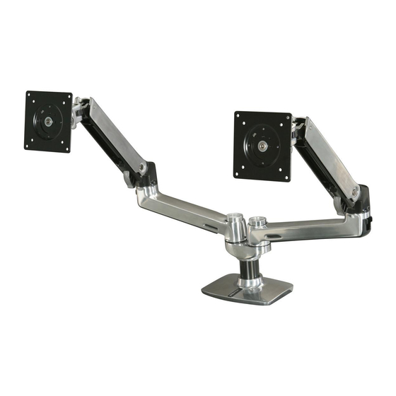
LX Dual Desk Mount Arm
13"
(330 mm)
C
8x
M4 x 10mm
8x
M4 x 10mm
2x
2x
M3 x 6mm
1x
User's Guide
5 - 20 lbs
0.5 - 12 lbs
(2.3 - 9.1 kg)
(0.23 - 5.4 kg)
70°
5°
D
E
1x
1x
1x
1x
2.5mm
2x
2x
Includes
Constant Force™
Technology
360°
4mm
4x
1 /12
Advertisement

Related Manuals for Ergotron LX Dual Side-by-Side Arm


Summary of Contents for Ergotron LX Dual Side-by-Side Arm
- Page 1 (330 mm) 180° 5° M4 x 10mm 2.5mm M4 x 10mm M3 x 6mm For the latest User Installation Guide please visit: www.ergotron.com User's Guide - English Includes Guía del usuario - Español Constant Force™ Manuel de l’utilisateur - Français Technology...
-
Page 2: Hazard Symbols
Hazard Symbols Symbol Signal Word Level of Hazard Review A NOTE indicates important information that helps you NOTE make better use of this product. These symbols alert users of a safety condi- tion that demands attention. All users should A CAUTION indicates either potential damage to be able to recognize and understand the CAUTION hardware or loss of data and tells you how to avoid the... - Page 3 Choose Mounting Method < .63" (16 mm) .5" - 1.63" (11 - 41 mm) 0.31" - 2"* < 3" (8 - 51 mm) (80 mm) *Bolt must be 1.42" - 2.6" (36 - 66 mm) centered in hole. CAUTION: For secure arm attachment and to avoid equipment damage, plate must make contact with underside of desk on both sides of the hole.
- Page 4 Attach Display M4 x 10mm M4 x 10mm 0° WARNING WARNING! Stored Energy Hazard: The arm mechanism is under tension and will move up rapidly, on its own, as soon as attached equipment is removed. For this reason, DO NOT remove equipment unless the arm has been moved to the highest position! Failure to follow this instruction may result in serious personal injury and/or equipment damage! 4 / 12...
- Page 5 Attach Notebook Attach portrait/landscape rotation stop screw M4 x 10mm M4 x 10mm Place Notebook Place docking station and notebook 5 /12 888-45-175-W-01 rev.F • 12/14...
- Page 6 Place Notebook Pa ds will help prevent notebook from slipping, but they will not hold all notebooks on the tray in all circumstances. Use caution while tilting the tray, since some angles may cause the notebook to fall off resulting in equipment damage or personal injury. 6 / 12 888-45-175-W-01 rev.F •...
- Page 7 Place docking station and notebook 7 /12 888-45-175-W-01 rev.F • 12/14...
- Page 8 >180º 180º WARNING: Desk Clamp Installations: The range of motion (side-to- side) for two Extensions/Arms on one pole mounted with the Desk Clamp option is limited to 180º forward (over front of desk clamp base). NOTE: Grommet Mount Installations: The range of motion (side-to- side) for two Extensions/Arms on one pole mounted with the Grommet Mount option is 360º...
- Page 9 NOTE: Leave enough slack in cable to allow full range of motion. Caution: To avoid the potential to pinch cables it is important to follow the cable routing instructions in this manual. Failure to follow these instructions may result in equipment damage or personal injury.
- Page 10 Important! You will need to adjust this product after installation is complete. Make sure all your equipment is properly installed on the product before attempting adjustments. This product should move smoothly and easily through the full range of motion and stay where you set it. If movements are too easy or diffi cult or if product does not stay in desired positions, follow the adjustment instructions to create smooth and easy movements.
- Page 11 Tilt – Forward and Backward 2.5mm CAUTION: DO NOT remove screw. Removing Increase Friction screw may cause damage to equipment. If this product moves too easily, then you'll need to increase friction: Decrease Friction If this product is too diffi cult to move, then you'll need to decrease friction: Rotate –...
- Page 12 Blink - Blink often to avoid dry eyes. Break • 2 to 3 minutes every 20 minutes • 15 to 20 minutes every 2 hours. For local customer care phone numbers visit: http://contact.ergotron.com NOTE: When contacting customer service, reference the serial number.
Need help?
Do you have a question about the LX Dual Side-by-Side Arm and is the answer not in the manual?
Questions and answers