Table of Contents
Advertisement
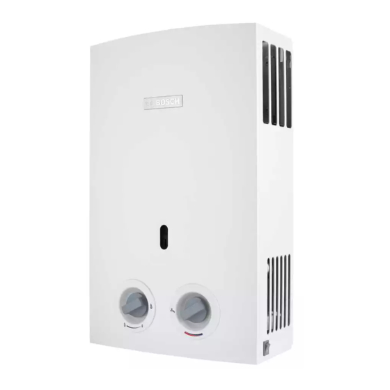
Gas tankless water heater
THERM 1000 O
W6 / W10 KB
Installation and use manual
Please read the installation instructions before installing the appliance!
Please read the operating instructions before operating the appliance!
Please observe the safety instructions in the operating instructions!
The installation site must meet the requirements for sufficient ventilation!
We suggest that the installation should be carried out by an authorized company Bosch!
6720818788-00.3V
Advertisement
Table of Contents

Related Manuals for Bosch THERM 1000 O


Summary of Contents for Bosch THERM 1000 O
- Page 1 Please read the operating instructions before operating the appliance! Please observe the safety instructions in the operating instructions! The installation site must meet the requirements for sufficient ventilation! We suggest that the installation should be carried out by an authorized company Bosch!
-
Page 2: Table Of Contents
2 | Index Index Gas connection ....14 Symbology ......3 Start-up . -
Page 3: Symbology
Symbology ▶ Switch the appliance off. ▶ Open doors and windows. 1.1 Symbology ▶ Request a visit from an authorized service Bosch. Warnings Assembly, modifications ▶ The appliance's assembly, as well as the installation Warnings in this document are identified by a... -
Page 4: Instructions Regarding The Appliance
• Conversion kit of natural gas for LPG and LPG for natural Capacity (l/min) gas. The conversion to another type of gas should only be Electronic ignition powered by type LR20 batteries carried out by an authorized service BOSCH. (2x1.5V) [GN] Appliance set for natural gas H... -
Page 5: Dimensions
Instructions regarding the appliance | 5 2.7 Dimensions 6720818788-03.2V Fig. 1 Water inlet Gas inlet Appliance Cold/Hot GN/GLP Ø 95 1/2” 1/2” W10/WD10 Ø 115 1/2” 1/2” Table 5 Dimensions in mm 6 720 818 788 (2015/11) -
Page 6: Appliance Construction
6 | Instructions regarding the appliance 2.8 Appliance construction 6720818788-07.1V Fig. 2 [1] Flue pipe connection [11] Electro valve 1 [2] Control device of the combustion gases [12] Outlet hot water [3] Chimney [13] Gas inlet [4] Temperature limiter [14] Fixation point [5] Combustion chamber [15] Ionization probe [6] Ignition probes... -
Page 7: Electrical Schema
Instructions regarding the appliance | 7 2.9 Electrical schema 6720818788-04.1V Fig. 3 [1] Control device of the combustion gases [2] Temperature limiter [3] Ignition unit [4] Micro switch [5] Electro valve [6] ON/OFF switch [7] Batteries (2x 1.5V) [8] Temperature Sensor (for WD model only) [9] Temperature Display (for WD model only) DANGER: Burns! -
Page 8: Operation Description
8 | Instructions regarding the appliance 2.10 Operation description Hot water This heater is equipped with electronic automatic ignition, thus its operation becomes simple. For such it is enough to: ▶ Open the gas and water shut-off valves and check the tightness of all the connections. -
Page 9: Technical Features
Instructions regarding the appliance | 9 2.11 Technical features Technical features Symbol Units W10 /WD10 Output Nominal input in standard conditions 11.8 Efficiency η 84.0 84.0 Data relating to the gas Supply pressure Natural gas H mbar L.P.G. (butane/propane) mbar 27.8 27.8 Consumption... -
Page 10: Use
▶ The initial start-up of the heater must be 3.3 Switch on and off done by a company from the Authorized Service Bosch who will provide the user Switch on with all the information required for the ▶ To switch on place the ON/OFF switch in I position. -
Page 11: Output Adjustment
Use | 11 3.5 Temperature adjustment ▶ Turning counter clockwise. Increases the flow and decreases the temperature 6720643462-07.1V Fig. 7 Switch off Fig. 10 ▶ Turning clockwise. 3.4 Output adjustment Decreases the flow and increases the temperature Less hot water. 3.6 Bleeding of the appliance Decrease output. -
Page 12: Fault Diagnosis
In the event of the company Bosch. number of cylinders being minor than the consumption of ▶ See the table 8 to find solutions for possible... - Page 13 Installation (only by qualified technicians) | 13 • All of the heaters should obligatorily be connected in an airtight way to a flue gas duct of proper dimension. False ogive • Avoid change of direction. • The flue duct should: Flue pipe –...
-
Page 14: Fixing Of The Appliance
14 | Installation (only by qualified technicians) 5.3 Fixing of the appliance 5.5 Gas connection To fix the appliance to the wall DANGER: ▶ Fix the appliance vertically, using the provided fixing Non-compliance with legal standards accessories. applicable may cause fire or explosion, causing material damage or personal injury or even death. -
Page 15: Start-Up
▶ Loosen the fixing screws from the chassis (Fig. 16). mbar. DANGER: The following operations described below should only be carried out by a company from the Authorized Service Bosch. 6.2 Conversion to another type of gas Only use the original conversion sets. 6720643462-14.1V The conversion should only be carried out by a company from the Authorized ServiceBosch. -
Page 16: Maintenance (Only By Qualified Technicians)
▶ Check that there are no leaks. ▶ After 10 minutes, operate the appliance again. If it reoccurs, an authorized company should be contacted 7.1 Periodic maintenance works Bosch. Functional check ▶ Check the proper operation of all the safety, regulation and verification elements. - Page 17 Maintenance (only by qualified technicians) | 17 Checking its operation: To check the proper operation of the combustion gas control device, proceed as follows: ▶ Remove the combustion gas duct. ▶ Replace it with a duct (with approximately 50cm) obstructed at the end. ▶...
-
Page 18: Problems
18 | Problems Problems The installation, maintenance or repair should only be carried out by an authorized service BOSCH. The following table describes the solutions for possible problems (solutions followed by * must only be carried out by an authorized service BOSCH). -
Page 19: Environmental Protection
Environmental protection | 19 Environmental protection The environmental protection is one of the principles of the group Bosch. We develop and produce products that are safe, environmentally friendly and economic. Our products contribute for the improvement of the safety and... - Page 20 Bosch Thermotechnik GmbH Junkersstrasse 20-24 D-73249 Wernau www.bosch-thermotechnology.com...
Need help?
Do you have a question about the THERM 1000 O and is the answer not in the manual?
Questions and answers