Bosch Therm 8000 S GWHC 27 CTDE Installation And Operating Instructions Manual
Condensing gas water heater
Hide thumbs
Also See for Therm 8000 S GWHC 27 CTDE:
Table of Contents
Advertisement
Quick Links
Condensing Gas Water Heater
Therm 8000 S
Installation and op erating instructions
Read installation manual prior
Read user manual before putti
Observe the warnin gs in the manuals!
The installation room must fulf
Installation by an authorised person only!
Give It Gas - operates solely as an ONLINE BUSINESS
Email: penny@giveitgas.co.za
to installation of this unit!
ng this unit in operation!
ill the ventilation requirements!
Tel: (011) 646 9439
Cell: (082) 452 4488
www.giveitgas.co.za
Advertisement
Table of Contents

Related Manuals for Bosch Therm 8000 S GWHC 27 CTDE


Summary of Contents for Bosch Therm 8000 S GWHC 27 CTDE
- Page 1 Condensing Gas Water Heater Therm 8000 S Installation and op erating instructions Read installation manual prior to installation of this unit! Read user manual before putti ng this unit in operation! Observe the warnin gs in the manuals! The installation room must fulf ill the ventilation requirements! Installation by an authorised person only! Give It Gas - operates solely as an ONLINE BUSINESS...
-
Page 2: Table Of Contents
2 | Index Index Installation of the ex haustion accessory and Safety information and symbology ....3 admission of air ..... .19 Key to symbols . -
Page 3: Safety Information And Symbology
Safety information and symbology | 3 If you smell combustion gases: Safety information and symbology B Turn o the heater (página 11). B Open doors and windows. 1.1 Key to symbols B Notify a gas tter. Warnings Installation, modi cations B The installation may only be carried out by registered Warnings in this document are framed and installers and shall comply wi... -
Page 4: Technical Characteristics And Dimensions
4 | Technical Characteristics and Dimensions Technical Characteristics and Dimensions 2.1 Declaration of conformity with relevant EEC – Flame failure device (ion ization ame rod sensor) regulations – Back ow temperature sensor – Inlet temperature sensor This appliance ful lls European directive requirements 90/396/EEC, 92/42/EEC, 73/23/EEC, 89/336/EEC and –... -
Page 5: Dimensions
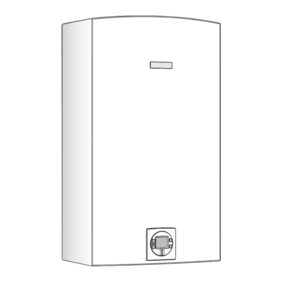
Technical Characteristics and Dimensions | 5 2.6 Dimensions 285,8 6720608948-14.2Av Fig. 1 [1] Front cover [2] Key pad [3] Cold water inlet: Ø 3/4 “ [4] Gas connection: Ø 3/4 “ [5] Hot water outlet: Ø 3/4 “ [6] Support bracket Therm 8000 S 6 720 680 174 (2012/09) -
Page 6: Appliance Overview
6 | Technical Characteristics and Dimensions 2.7 Appliance overview 6720608948-06.1AL Fig. 2 [1] Air admission adaptor (not included) [10] Over heat prevention (temperature limiter) [2] Condensing Heat Exchanger [11] Observation window [3] Heat exchanger [12] Ignition electrodes [4] Primary fan (Mixer) [13] Back ow temperature sensor [5] Control unit [14] Ionization sensor... -
Page 7: Electrical Diagram
Technical Characteristics and Dimensions | 7 2.8 Electrical diagram T=90°C T=104°C T=110°C 6720608917-02.1AL Fig. 3 Electrical scheme [1] Intlet water temperature sensor [2] Outlet water temperature sensor [3] Back ow temperature sensor [4] Cascading output connection [5] Cascading input connection [6] Ionization sensor [7] Water ow sensor [8] Room sealed box temperature sensor... -
Page 8: Technical Data
8 | Technical Characteristics and Dimensions 2.9 Technical data Technical characteristics Symbol Units GWHC 27 CTDE Power and ow kW (Btu/h) 47 (160 370) i n i kW (Btu/h) 6 (20 475) Useful power (adjustment range) 6 - 47 o l f kW (Btu/h) 48,4 (165 295) i n i... -
Page 9: Operational Instructions
Regulation | 9 2.10 Operational instructions Hot water In this case, if the attempts to ig nite go on too long, the security mechanisms prevent operation. Open the gas and water valves and ensure that all joints are hermetic. Security cut-o due to excessive water heating Place the principle switch (Fig. -
Page 10: Description Lcd Display
10 | Operating instructions 4.1 Description LCD Display CAUTION: Do not use any cleaning agressive or corrosive agents to clean the window. Fig. 9 Flame indicator Fig. 5 Power bar indicator (input) Fig. 10 Solar mode indicator 6720608920 -31 1AL Fig. -
Page 11: Connect And Disconnect The Appliance
Operating instructions | 11 B Open water valve. B Once the desired temperature is set, open the hot water tap. These appliance has an electronically Check for water leaks at all joints. controlled gas valve that modulates the burner input in response to both varying hot water ow rates and/or changes in any incoming and outgoing water temperatures. -
Page 12: Remote Control Operation (Accessory Nº 7 709 003 756)
12 | Operating instructions 4.7 Remote control operation (accessory nº 7 709 B Test the remote control in fr ont of the electronic box by simultaneously pressing the control keys. 003 756) This appliance ful lls European directive requirements 1999/ 5/CEE (R&TTE) and corresponds to the speci cations described in the cor-responding CE certi cate of proof. -
Page 13: Program Button
Operating instructions | 13 4.8 Program button The appliance does not have a designated default priority. Priority is attributed when the rst user selects a temperature Program button can be used/programed in the appliance and in (see chapter 4.4). the remote control. The following symbol appears for other users Programing "Program"... -
Page 14: Locked Condition
14 | Installation instructions 4.12 Locked condition This condition is only valid fo r appliances with one or more remote controls installed. Fig. 18 Error code After following instructions in dicated in “Troubleshooting” 6720608920-33.1AL section, Fig. 20 Locked condition B press reset button rmly in order to return heater to normal Whenever LCD shows the temperature setting cannot... -
Page 15: Important Remarks
Installation instructions | 15 5.1 Important remarks 5.2 Selection of location for installation B Before installation, consult the gas company and current Considerations relevant to location legislation regarding gas appliance and site ventilation. B Ful l requirements speci c to each country. B Install a gas shut-o tap as close to the appliance as B The heater must not installed above a source of heat. -
Page 16: Installation Of Xing Bracket
16 | Installation instructions 5.5 Installation CAUTION: Possibility of damage caused by foreign bodies! B Purge all tubes to eliminate possible foreign bodies. B Remove appliance from packaging. 6720608913-04.1AL B Ensure that all indica ted parts are included. B Remove the plastic caps from the gas and water connections. -
Page 17: Water Connection
Installation instructions | 17 5.6 Water connection B Lift front cover panel upward and remove. B Mark the hot and cold water pipes in order to avoid confusion. 6720608913-06.1AL Fig. 24 B Fix the appliance in a vertical position. 6720608948-03. 1 AL Fig. -
Page 18: Connecting The Condensate Water
18 | Installation instructions 5.7 Connecting the condensate water drain to the The condensate must be disposed of in appliance accordance with local codes. 5.8 Gas connection DANGER: If local regulations are not follow exactly, a re or explosion may result causing property damage, personal injury or loss of life. -
Page 19: Installation Of The Exhaustion Accessory And Admission Of Air
Installation instructions | 19 B Tighten the 4 screws of the acc essory of admission of air Fig. 29 , [2]. 6720608948-04. 1 AL Fig. 28 [1] Gas piping 5.9 Installation of the exhaustion accessory and admission of air It is mandatory the installation of the accessories for the exhaustion / admission of air, cód. -
Page 20: Filling The Condensate Trap
20 | Installation instructions B Tighten the 3 screws of the exhaustion accessory Fig. B Tighten the 3 screws of the concentric accessory. 30 ,[2]. 6720680174-06.1Av Fig. 31 Concentric accessory [1] Concentric accessory [2] Accessory 8 705 507 042 5.10 Filling the condensate trap DANGER: 6720608920-25.1AL Before the rst start up of the appliance,... - Page 21 Installation instructions | 21 5.10.1Filling the condensate trap before vent pipe B Remove the clip and disconnect the drain tube, see Fig. 33 . installation B Fill the condensate trap by pouring approx.14 oz. (400ml) of water into the exhaust accessory on the top of the appliance, see Fig.
-
Page 22: Admission / Exhaustion Accessories (Accessory Ø 80/125 Mm)
22 | Admission / exhaustion accessories (accessory Ø 80/125 mm) Admission / exhaustion accessories DANGER: Make sure that all ue connections are tighten sealed. (accessory Ø 80/125 mm) B Failure to follow this requirement may cause dangerous exhaust gases to enter 6.1 Admission/exhaustion accessories (diameter living space which may result causing in mm) -
Page 23: Fitting Instructions
Admission / exhaustion accessories (accessory Ø 80/125 mm) | 23 6.2 Fitting instructions • The permissible maximum ue/air pipe length, Lmax, for the various possible ue con gur ations is speci- ed in the tables starting on chapter 8.6. • If the concentric ue/air pipe enters a chimney below ground level, the appliance may register a fault and shut down in cold weather due to ice formation. -
Page 24: Approved Ue Systems
24 | Admission / exhaustion accessories (accessory Ø 80/125 mm) 6.4 Approved ue systems 6.4.1 Exhaustion type A Outdoor installation with accessory nº 7 709 003 732 Fig. 39 Ref. Description Minimum distance Installation next to window; Inst allation next to door; Installation near of any open for air >... - Page 25 Admission / exhaustion accessories (accessory Ø 80/125 mm) | 25 6.4.2 Exhaustion type B Ø 135 mm est. Ø 80 mm Ø 80 mm Ø 80 / 125 mm Ø 80 mm Ø 80 mm 6720608948-11.1AL 6720608920-36.1AL Fig. 40 6.4.3 Exhaustion type C Ø...
- Page 26 26 | Admission / exhaustion accessories (accessory Ø 80/125 mm) 6.4.4 Exhaustion type C Ø 135 mm est. Ø 80 / 125 mm 6720608948-10.1AL Fig. 42 6.4.5 Exhaustion type C Ø 80 mm 6720608920-28.1AL Fig. 43 6 720 680 174 (2012/09) Therm 8000 S...
-
Page 27: Electrical Connection
Electrical connection | 27 6.4.6 Exhaustion type C Ø 135 mm est. Ø 80 / 125 mm Ø 80 mm Ø 80 mm 6720608920-29.1AL Fig. 44 7.1 Connection Electrical connection The electrical connection should be according to current regulations regarding DANGER: Risk of electric shock! domestic electrical installations. -
Page 28: Position Of The Fuses In Control Unit
28 | Installation instructions B Check the fuses in the printed circuit board, see Fig. 47 , pos. 3. 6720608913-09.1AL Fig. 45 Power cable connections 7.3 Position of the fuses in control unit To check fuses, proceed as follows; B Remove the front cover, see Fig. 23 . 6720608158-78.1AL B Remove the three screws from the control unit (Fig. -
Page 29: Measuring Gas Pressure
Installation instructions | 29 B Press and hold "Program" button and press ON/OFF button DANGER: to turn appliance ON (Fig. 49 ). B The following operations must be carried out by a quali ed technician. 8.2 Measuring gas pressure Con rm gas pressure after installation. Connecting manometer B Shut o gas supply. - Page 30 30 | Installation instructions Measuring CO (Combustion cover Installed): CAUTION: B Open all hot water taps to achiev e a ow rate of at least 15 l/ One factor that may a ect CO levels is m (1 tub and 2 sinks should be su cient). If heater display improper gas pressure.
- Page 31 Installation instructions | 31 B Verify CO readings in P2 mode. B Repeat steps 1 and 2 as necesssary until CO values are within the speci ed ranges. As soon as the levels of CO2 ar e correct, verify the values of CO corresponds to the limits of the table 11.
-
Page 32: Program Values
32 | Installation instructions 8.4 Program values CAUTION: Misadjusted program values This section describes details on programming the appliance. can lead to appliance malfunction, errors, For most applications the fact ory default values will provide and service calls. robust and stable operation. Program Description Factory default Comment... -
Page 33: Control Board Diagnostics
Installation instructions | 33 8.5 Control board diagnostics Diagnostic menu To acess the diagnostic menu, proceed as follow: 3rd most recent error B Press ON/OFF button to turn o the appliance. 4th most recent error B Press and hold "Program" button and press ON/OFF 5th most recent error button to turn appliance ON. - Page 34 34 | Installation instructions Pressure drop equivalence of the conducts and exhaustion Exhaust accessories Straight section length___ x 1 = ________ Equivalence in meters 90° elbows (qty) ___x 1 = ________ Description Ø80/80mm Ø80/125mm 45° elbows (qty) ___x 0.5 = ________ 30°...
- Page 35 Installation instructions | 35 Example table: Intake Concentric conduts Straight section length _4_ x 1= Straight section length 5 x 1 = 90° elbows (qty) _1_ x 1 = 90° elbow (qty) _1_ x 2 = 45° elbows (qty) _0_ x 0.5 = 45°...
- Page 36 36 | Installation instructions Fan speed for separate tubes Ø80/80 mm Mode Conduct length Fan speed From 1 m until 6 m from 6.1 m until 14m from 14.1m until 16 m Table 23 1) Total conducts lengths of table 18. Do not count with the rst elbow and the accessory of wind/rain protection.
-
Page 37: Maintenance
B Your appliance must only be serviced by a Bosch Technical Assistance delegate. B Verify CO levels (ver chapter 8.3) and correct it if B Use only genuine accessories. -
Page 38: Verify The Fuses In The Control Board
38 | Maintenance B Dismantle the cold water inlet pipe, see Fig. 55 . B Remove the six screws from the back cover of the control unit, see Fig. 57 , pos.2. 672 0608 158 -78.1AL Fig. 57 Fuses position Fig. - Page 39 Maintenance | 39 It is mandatory to propely replace the gaskets and o-rings. B Assemble the condensate unit and all other parts in reverse order of disassembly. 9.3.1 Cleaning the condensate trap WARNING: Material damage! B Place a suitable container underneath the appliance before unscrew the condensate trap cover.
-
Page 40: Startup After Maintenance
40 | Maintenance B Remove the clip and disconnect the drain tube, see Fig. 61 . B Check water level in the cond ensate trap (see Fig. 63). 6720 6720608948-05.1AL Fig. 61 B Fill the condensate trap by pouring approx.14 oz. (400ml) 6720608948-12.1AL Fig. -
Page 41: Problem Solving
Problem solving | 41 10 Problem solving 10.1 Problem/Cause/Solution To remove error code from the display, press the reset button. Display Cause Solution Fault in the ue gas limiter. 1. Check continuity of the ue gas limiter (normaly closed). Temperature above 110 °C 2. - Page 42 42 | Problem solving Display Cause Solution (Flashing) Outlet temperature sensor not 1. Check that the sensor is rmly at tached to the vertical section of the sensing expected output hot water pipe. temperature. (Status message, 2. Ensure that hot water sensor is not placed on any bends in the hot not an error) water pipe or misreading may occur.
- Page 43 Problem solving | 43 Display Cause Solution Hot water temperature sensor 1. Check the correct position and xation of the NTC sensor. (NTC) at the exit of the 2. Check the electric connections and connectors of the hot water appliance detect a high temperature sensor.
- Page 44 44 | Problem solving Display Cause Solution No ame ionization detected 1. Verify that all manual gas shut o valves are open. with water ow. 2. Check gas type. 3. Check gas pressure. 4. Reset error code and open a water tap to cycle the heater in an e ort to purge air.
Need help?
Do you have a question about the Therm 8000 S GWHC 27 CTDE and is the answer not in the manual?
Questions and answers