Table of Contents
Advertisement
One Technology Way • P.O. Box 9106 • Norwood, MA 02062-9106, U.S.A. • Tel: 781.329.4700 • Fax: 781.461.3113 • www.analog.com
Evaluation Board for the
FEATURES
Self-contained board including PLL, VCO, loop filter (35 kHz),
25 MHz TCXO reference, USB interface, and voltage
regulators
Accompanying software allows control of synthesizer
functions from a PC
Choice of power supply via USB or external feeding
Typical phase noise performance of −104 dBc/Hz @ 3 kHz
offset from carrier (1 GHz output frequency)
EVALUATION KIT CONTENTS
EVAL-ADF4351EB1Z
board
USB Standard-A to Mini-B cable
CD that includes
Self-installing software that allows users to control the
board and exercise all functions of the device
Electronic version of the
Electronic version of the UG-435 user guide
ADDITIONAL EQUIPMENT
PC running Windows XP or more recent version
Spectrum analyzer
Oscilloscope (optional)
PLEASE SEE THE LAST PAGE FOR AN IMPORTANT
WARNING AND LEGAL TERMS AND CONDITIONS.
ADF4351
ADF4351
data sheet
EVALUATION BOARD
Evaluation Board User Guide
Fractional-N PLL Frequency Synthesizer
DOCUMENTS NEEDED
ADF4351
data sheet
REQUIRED SOFTWARE
Analog Devices ADF435xPLL software (Version 4 or higher)
ADIsimPLL™
GENERAL DESCRIPTION
This board is designed to allow the user to evaluate the perfor-
mance of the
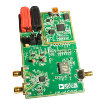
loops (PLLs). Figure 1 shows the board, which contains the
ADF4351
integrated synthesizer and VCO, SMA connectors for
the output signal, power supplies, a reference oscillator, and an
USB connector. There is also a loop filter (35 kHz) on board.
The evaluation board is set up for a 25 MHz PFD comparison
frequency. An on-board TCXO provides the 25 MHz reference
frequency.
The package also contains Windows® software (XP or later) to
allow easy programming of the synthesizer.
Figure 1. EVAL-ADF4351EB1Z
Rev. 0 | Page 1 of 20
ADF4351
frequency synthesizer for phase-locked
UG-435
Advertisement
Table of Contents

Related Manuals for Analog Devices UG-435


Summary of Contents for Analog Devices UG-435
-
Page 1: Features
25 MHz TCXO reference, USB interface, and voltage REQUIRED SOFTWARE regulators Analog Devices ADF435xPLL software (Version 4 or higher) Accompanying software allows control of synthesizer ADIsimPLL™ functions from a PC Choice of power supply via USB or external feeding GENERAL DESCRIPTION Typical phase noise performance of −104 dBc/Hz @ 3 kHz... -
Page 2: Table Of Contents
UG-435 Evaluation Board User Guide TABLE OF CONTENTS Features ....................1 Input Signals...................4 Evaluation Kit Contents ..............1 Loop Filter ..................4 Additional Equipment ..............1 Output Signals ................4 Documents Needed ................1 Evaluation Board Setup Procedure ..........5 Required Software ................1 Software Installation ..............5... -
Page 3: Quick Start Guide
Evaluation Board User Guide UG-435 QUICK START GUIDE Follow these steps to quickly evaluate the ADF4351 device: Select the USB board connection and the ADF4351 device in the Select Device and Connection tab of the software Install the ADF435x software from the CD. -
Page 4: Evaluation Board Hardware
UG-435 Evaluation Board User Guide EVALUATION BOARD HARDWARE EVAL-ADF4351EB1Z schematics are shown in Figure 22 to Figure 24. POWER SUPPLIES EVAL-ADF4351EB1Z can be powered either from the USB port or via dc power connectors (4 mm banana connectors). When feeding via banana connectors, 3.75 V to 5.5 V is a suitable feeding voltage. -
Page 5: Evaluation Board Setup Procedure
ADF435x_Setup.msi again. Note that to install the dotnetfx35.exe, you need to have Windows Installer 3.1 or later installed. Install the Analog Devices ADF435x PLL software by Figure 4. Windows XP ADF435x Software Installation, Setup Wizard double-clicking ADF435x_Setup.msi. Click Next. - Page 6 UG-435 Evaluation Board User Guide Figure 6. Windows XP ADF435x Software Installation, Confirm Installation Figure 8. Windows XP ADF435x Software Installation, Installation Complete Click Next. Click Close. Windows Vista/7 Software Installation Guide Figure 7. Windows XP ADF435x Software Installation, Logo Testing Click Continue Anyway.
- Page 7 Evaluation Board User Guide UG-435 Figure 10. Windows Vista/7 ADF435x Software Installation, Select Figure 12. Windows Vista/7 ADF435x Software Installation, Start Installation Installation Folder Click Install. Choose an installation directory and click Next. Figure 13. Windows Vista/7 ADF435x Software Installation, Installation Figure 11.
- Page 8 Installation Figure 15. Windows XP USB Adapter Board Driver Installation, Installation Click Finish. Options Click Next. Note that Figure 15 may list Analog Devices RFG.L Eval Board instead of ADF4xxx USB Adapter Board. Rev. 0 | Page 8 of 20...
-
Page 9: Evaluation Board Software
Confirm that SDP board connected, ADF4xxx USB Adapter EVAL-ADF4351EB1Z on a CD. To install the software, see Board connected, or Analog Devices RFG.L Eval Board the Software Installation section. connected is displayed at the bottom left of the window. Otherwise, the software has no connection to the evaluation To run the software, click the ADI ADF435x file on the desktop board. - Page 10 UG-435 Evaluation Board User Guide The Main Controls tab controls the PLL settings (see Figure 19). In the Sweep and Hop tab, you can make the device sweep a range of frequencies, or hop between two set frequencies. Use the Reference Frequency text box to set the correct reference frequency and the reference frequency divider.
-
Page 11: Evaluation And Test
Evaluation Board User Guide UG-435 EVALUATION AND TEST To evaluate and test the performance of the ADF4351, use the following procedure: Install ADF435x software. Connect the evaluation board to a PC using the supplied USB cable. Follow the hardware driver installation procedure that appears. -
Page 12: Evaluation Board Schematics And Artwork
UG-435 Evaluation Board User Guide EVALUATION BOARD SCHEMATICS AND ARTWORK Figure 22. Evaluation Board Schematic (Page 1) Rev. 0 | Page 12 of 20... - Page 13 Evaluation Board User Guide UG-435 Figure 23. Evaluation Board Schematic (Page 2) Rev. 0 | Page 13 of 20...
- Page 14 UG-435 Evaluation Board User Guide Figure 24. Evaluation Board Schematic (Page 3) Rev. 0 | Page 14 of 20...
- Page 15 Evaluation Board User Guide UG-435 Figure 25. Top Side Figure 26. Layer 2 (GND Plane) Rev. 0 | Page 15 of 20...
- Page 16 UG-435 Evaluation Board User Guide Figure 27. Layer 3 (Power Plane) Figure 28. Bottom Side Rev. 0 | Page 16 of 20...
-
Page 17: Ordering Information
Evaluation Board User Guide UG-435 ORDERING INFORMATION BILL OF MATERIALS Table 1. Reference Designator Description Ceramic capacitor, 2.7 nF, 0603, 100 V, X7R Ceramic capacitor, 47 nF, 0603, 25 V, X7R Ceramic capacitor, 680 pF, 0603, 50 V, X7R, SMD C4, C27, C32, C34 Capacitor, 1 µF, 0603, 10 V, X5R... - Page 18 UG-435 Evaluation Board User Guide NOTES Rev. 0 | Page 18 of 20...
- Page 19 Evaluation Board User Guide UG-435 NOTES Rev. 0 | Page 19 of 20...
- Page 20 By using the evaluation board discussed herein (together with any tools, components documentation or support materials, the “Evaluation Board”), you are agreeing to be bound by the terms and conditions set forth below (“Agreement”) unless you have purchased the Evaluation Board, in which case the Analog Devices Standard Terms and Conditions of Sale shall govern. Do not use the Evaluation Board until you have read and agreed to the Agreement.
- Page 21 Mouser Electronics Authorized Distributor Click to View Pricing, Inventory, Delivery & Lifecycle Information: Analog Devices Inc. EVAL-ADF4351EB1Z...
Need help?
Do you have a question about the UG-435 and is the answer not in the manual?
Questions and answers