Honeywell T6 Pro Hydronic Installation Instructions Manual
Hide thumbs
Also See for T6 Pro Hydronic:
- User manual (13 pages) ,
- Installation instructions manual (37 pages) ,
- User manual
Advertisement
T6 Pro Hydronic
Programmable Thermostat
Installation Instructions
Package Includes:
• T6 Pro Hydronic Programmable
Thermostat
• Floor sensor (model AQ12C20)
• UWP™ Mounting System
• Honeywell Standard Installation Adapter
(J-box adapter)
• Honeywell Decorative Cover Plate –
Small; size 4-49/64 in x 4-49/64 in x
11/32 in (121 mm x 121 mm x 9 mm)
• Screws and anchors
• 2 AA Batteries
• Installation Instructions and User Guide
Welcome!
T6 Pro Hydronic Programmable Thermostat can be used
to control the ambient air temperature or floor temperature
or both. You can choose among the following temperature
control modes.
A mode: Controls and displays the ambient air temperature
only.
F mode: Controls and displays the floor temperature only
using an external floor temperature sensor. This control
mode is suitable for areas such as bathrooms where floor
temperature could be scheduled to be warm only during
occupied, morning and evening periods.
• Floor temperature is indicated by "FLR" above the actual
floor temperature.
• Actual ambient air temperature could also be displayed in
the Thermostat MENU/TEMP.
AF mode: Controls and displays the ambient air temperature
as well as maintains the floor temperature within desired
floor temperature limits using an external floor temperature
sensor. Setting the minimum and maximum floor
temperature limits is a way to enhance
comfort and to protect the floor covering at
the same time.
• Actual floor temperature could also be
displayed in the Thermostat MENU/
TEMP.
NOTE: To set the thermostat temperature
control mode, go to "Installer setup (ISU)"
on page 7.
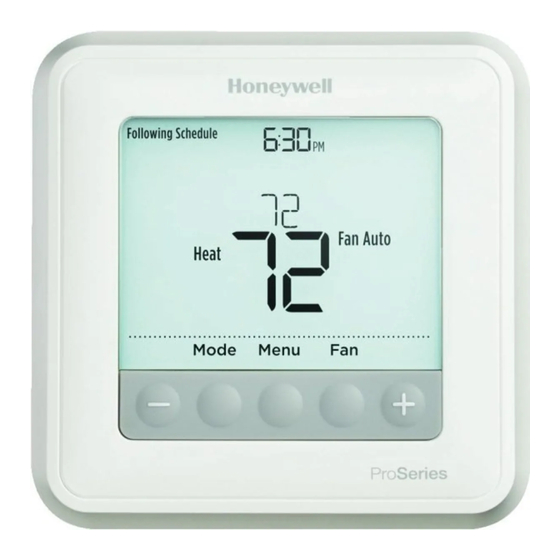
A, AF mode; main screen
F mode; main screen
Temperatures menu
Back
Advertisement
Table of Contents

Related Manuals for Honeywell T6 Pro Hydronic


Summary of Contents for Honeywell T6 Pro Hydronic
-
Page 1: Programmable Thermostat
• Installation Instructions and User Guide Welcome! A, AF mode; main screen T6 Pro Hydronic Programmable Thermostat can be used to control the ambient air temperature or floor temperature or both. You can choose among the following temperature control modes. - Page 2 Optional Cover Plate installation NOTE: If Optional Cover Plate is not required, see “UWP Mounting System installation” below. Use the Optional Cover Plate when: • Mounting the thermostat to an electrical junction box • Or when you need to cover paint gap from old thermostat.
-
Page 3: Power Options
Power options Insert R and C wires into designated terminals for primary AC power (C terminal is optional if batteries are installed, but it is recommended). Remove wires by Insert AA batteries for primary or backup depressing the terminal tabs. power. - Page 4 Wiring terminal designations Unused Input for auxiliary wired floor or indoor sensors Unused Unused Unused - W2 Unused Unused Unused Heat relay (stage 1) 24 VAC common. If a second transformer, separate from the one powering the Unused heating equipment, is used, use the common from that transformer.
- Page 5 Floor temperature sensor installation Floor sensor conduit position in a slab T6 Pro Hydronic thermostat is compatible with the following 10K ohm Honeywell floor FLOOR SENSOR CONDUIT temperature sensors: AQ12C20, AC112-01, AC130-01. SLAB The floor temperature sensor needs to be...
-
Page 6: Thermostat Mounting
Thermostat mounting 1. Push excess wire back into the wall opening. 2. Close the UWP door. It should remain closed without bulging. 3. Align the UWP with the thermostat, and push gently until the thermostat snaps in place. 4. Turn the power on at the breaker box or switch. - Page 7 Installer setup (ISU) 1 Press and hold CENTER and buttons for approximately 3 seconds to enter advanced menu. 2 Press Select to enter ISU. 3 Press Select to cycle through menu setup options. 4 Press to change values or select from available options.
- Page 8 Advanced setup options (ISU) # ISU ISU Name ISU Options (factory defaults Notes in bold) Heating Cycle Rate 1 - 12 This ISU allows you to limit the maximum number (Cycles per hour) of times the system can cycle in a 1 hour period measured at a 50% load.
- Page 9 Advanced setup options (ISU) # ISU ISU Name ISU Options (factory defaults Notes in bold) Minimum Floor 40 °F to 89 °F* (72 °F); *If the floor temperature is below that limit, the Temperature Limit 4.5 °C to 31.5 °C* (22.2 °C) heating will be activated regardless of the ambient Air temperature.
-
Page 10: Installer System Test
Installer system test To perform a System Test: 1 Press and hold CENTER and buttons for approximately 3 seconds to enter advanced menu. to go to TEST. Press Select to enter 2 Use System Test. 3 Use to change between Heat or Ver (thermostat version information). -
Page 11: Specifications
Specifications Temperature Setpoint and Limit Ranges See ISU settings 431, 432, 575, 576, and 578 starting on page 8. Working Ambient Temperature 32 °F to 120 °F (0 C° to 48.9 °C) Operating Ambient Temperature 37 °F to 102 °F (2.8 °C to 38.9 °C) Shipping Temperature -20 °F to 120 °F (-28.9 °C to 48.9 °C) Operating Relative Humidity... -
Page 12: Customer Assistance
Customer assistance For assistance with this product, please visit customer.honeywell.com. Or call Honeywell Customer Care toll-free at 1-800-468-1502. Pull to remove the thermostat from the UWP. Home and Building Technologies In the U.S.:...
Need help?
Do you have a question about the T6 Pro Hydronic and is the answer not in the manual?
Questions and answers