
Related Manuals for Supermicro 8U SuperBlade


Summary of Contents for Supermicro 8U SuperBlade
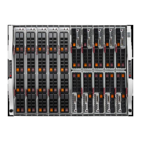
- Page 1 8U SuperBlade® 5 MP and 10 DP Blade System 20 DP Blade System User’s Manual Revision 1.0...
- Page 2 This product, including software and documentation, is the property of Supermicro and/or its licensors, and is supplied only under a license. Any use or reproduction of this product is not allowed, except as expressly permitted by the terms of said license.
-
Page 3: About This Manual
Refer here for details on installing the 8U SuperBlade system into a rack. Chapter 4: System Modules This chapter covers modules in the 8U SuperBlade system, as well as the CMM module and configuring double-wide bays. Chapter 5: Power Supply Modules This chapter covers the system power supplies and their installation. - Page 4 8U SuperBlade User’s Manual Notes...
-
Page 5: Table Of Contents
..............1-10 Operating System Support..............1-10 Remote Management ................1-10 Computing Density/Power ..............1-10 High-Efficiency Power Supplies ............1-11 1-8 Returning Merchandise for Service ..........1-11 1-9 Contacting Supermicro ..............1-12 Chapter 2 Standardized Warning Statements .....2-1 2-1 About Standardized Warning Statements ........2-1 Warning Definition...................2-1 Installation Instructions ................2-3 Circuit Breaker ..................2-4... - Page 6 8U SuperBlade User’s Manual Power Cable and AC Adapter ..............2-15 Chapter 3 Setup and Installation ..........3-1 3-1 Overview .....................3-1 3-2 Unpacking the System ..............3-1 Choosing a Setup Location..............3-1 Rack Precautions..................3-2 Server Precautions .................3-2 Rack Mounting Considerations ...............3-2 Ambient Operating Temperature ............3-2 Reduced Airflow ...................3-2...
- Page 7 Chapter 5 Power Supply Modules ..........5-1 5-1 Power Supply Modules ..............5-1 Power Supply Failure................5-4 Installing a Power Supply................5-4 Removing a Power Supply..............5-4 5-2 Redundant Power Supplies .............5-5 5-3 Power Supply Fans ................5-6 Appendix A System Specifications ........... A-1 A-1 Enclosure Specifications ..............
- Page 8 8U SuperBlade User’s Manual Notes...
- Page 9 List of Figures Figure 3-1. Positioning the Enclosure Template ..........3-4 Figure 3-2. Securing the Rails to the Rack ............3-4 Figure 3-3. Attaching the Optional Handles ............3-5 Figure 3-4. Enclosure Installed into Rack ............3-6 Figure 4-1. 8U 820C Enclosure with 100G Switch: Rear View ......4-1 Figure 4-2.
- Page 10 8U SuperBlade User’s Manual Notes...
- Page 11 List of Tables Table 1-1. Networking Module Solutions ............1-4 Table 1-2. 8U SuperBlade Enclosures..............1-6 Table 1-3. Number of Network Modules that May Be Installed in each Enclosure....................1-6 Table 1-4. Enclosure Models and Power Supply Combinations .......1-8 Table 4-1. Typical 8U Blade System Module Configuration: Rear View ...4-2 Table 4-2.
- Page 12 8U SuperBlade User’s Manual Notes...
-
Page 13: Chapter 1 Introduction
4. Install the power supply modules into the rear of the 8U SuperBlade chassis. See "Installing a Power Supply" on page 5-4 for details. 5. Install the CMM module and any switch modules into the rear of the 8U SuperBlade chassis. a. For the CMM module, see "CMM Module Installation"... -
Page 14: Software Mode Selection
Install the hard disk drives into each module. Refer to the blade module user’s manual for details. e. Install your blade modules into your 8U SuperBlade chassis. Refer to the blade module user’s manual for details. 7. Connect the power cords for your 8U SuperBlade system’s power supply and plug them into your power source ONLY after you have installed and secured all system components. -
Page 15: Product Checklist Of Typical Components
Blade Enclosure (x1): SBE-820C/CB/J/JB, 822/820D, 622 and 422 (8U, 10 full-height 2-socket or 20 half-height blades 4-socket) • Blade Unit (minimum of 2, 10 or 20 maximum): See the Supermicro website (http:// www.supermicro.com/products/superblade/) for a complete list of blades that can be mounted in your system. -
Page 16: Table 1-1. Networking Module Solutions
8U SuperBlade User’s Manual For some details on the combinations and types of networking modules available, see Table 1-1 below. See the SuperBlade Network Modules User Manual for full details on available modules for the SuperBlade system. Table 1-1. Networking Module Solutions... - Page 17 Chapter 1: Introduction Table 1-1. Networking Module Solutions (Continued) 8U Enclosure Model Model Speed Protocol SBE820C(B) SBE820J(B) Notes 56x 10G/2.5G/1G Ethernet downlinks, 2x 40G Ethernet QSFP+ or, 1x 40G and 4x 10G Ethernet uplinks, 1 console MBM-XEM-002 Ethernet Up to 2 Up to 4 port, 1 USB port PHY: 1280G/40G...
-
Page 18: Blade Enclosure Features
8U SuperBlade User’s Manual Blade Enclosure Features Supermicro's blade enclosures are designed to house from 10 to 20 blade units. Each accommodates up to eight power supplies. The enclosure mid-plane allows the blade units to share power, cooling and networking. -
Page 19: Power
Chapter 1: Introduction Power The typical blade enclosure features a 2200W power system composed of four, six, or eight power supply modules. An alternate configuration (and required for a full 10 or 20-blade system) features a total of four power supply modules for redundancy. This power redundancy feature allows you to replace the failing power module while the backup module takes over to keep the system running. -
Page 20: Power Supply Features
Power Supply Features The 8U SuperBlade enclosure comes standard with one CMM module and up to eight power supplies. Information on the power supplies is summarized below. See Section 4-1: Chassis Management Module on page 4-3... -
Page 21: Power Supply Modules
AC power is present and green when the power is on. Supermicro's high-efficiency blade system power supplies deliver continuous redundant power up to 96% peak efficiency. Each power supply module includes a management module that monitors the power supplies and the power enclosure. -
Page 22: Power Cord
Special Design Features Supermicro's 8U SuperBlade offers special design features, some of which no other blade server can duplicate. These features give you extraordinary flexibility in configuring a blade system for your own particular needs. -
Page 23: High-Efficiency Power Supplies
During the warranty period, contact your distributor first for any product problems. For faster service, RMA authorizations may be requested online at: http://www. supermicro.com/support/rma/ 1-11... -
Page 24: Contacting Supermicro
8U SuperBlade User’s Manual Contacting Supermicro Headquarters Address: Super Micro Computer, Inc. 980 Rock Ave. San Jose, CA 95131 U.S.A. Tel: +1 (408) 503-8000 Fax: +1 (408) 503-8008 marketing@supermicro.com (General Information) Email: support@supermicro.com (Technical Support) Website: www.supermicro.com Europe Address: Super Micro Computer B.V. -
Page 25: Chapter 2 Standardized Warning Statements
The following statements are industry standard warnings, provided to warn the user of situations which have the potential for bodily injury. Should you have questions or experience difficulty, contact Supermicro's Technical Support department for assistance. Only certified technicians should attempt to install or configure components. - Page 26 8U SuperBlade User’s Manual Warnung WICHTIGE SICHERHEITSHINWEISE Dieses Warnsymbol bedeutet Gefahr. Sie befinden sich in einer Situation, die zu Verletzungen führen kann. Machen Sie sich vor der Arbeit mit Geräten mit den Gefahren elektrischer Schaltungen und den üblichen Verfahren zur Vorbeugung vor Unfällen vertraut.
-
Page 27: Installation Instructions
Chapter 2: Standardized Warning Statements 이 경고 기호는 위험이 있음을 알려 줍니다 . 작업자의 신체에 부상을 야기 할 수 있는 상태에 있게 됩니다 . 모든 장비에 대한 작업을 수행하기 전에 전기회로와 관련된 위험 요소들을 확인하시고 사전에 사고를 방지할 수 있도록 표준 작업절차를 준수해 주시기 바랍니다... -
Page 28: Circuit Breaker
8U SuperBlade User’s Manual ﻣﺼﺪر ﻟﻠﻄﺎﻗﺔ اﻟﻨﻈﺎم إﻟﻰ ﻗﺒﻞ ﺗﻮﺻﯿﻞ ﺘﺮﻛﯿﺐ اﻗﺮ إرﺷﺎدات اﻟ 시스템을 전원에 연결하기 전에 설치 안내를 읽어주십시오 . Waarschuwing Raadpleeg de installatie-instructies voordat u het systeem op de voedingsbron aansluit. Circuit Breaker Warning! This product relies on the building's installation for short-circuit (overcurrent) protection. -
Page 29: Power Disconnection Warning
Chapter 2: Standardized Warning Statements ﻓﻲ اﻟﺘﻲ ﺗﻢ ﺗﺜﺒﯿﺘﮭﺎ ﻣﻦ اﻟﺪواﺋﺮاﻟﻘﺼﯿﺮة اﻟﺤﻤﺎﯾﺔ ﻣﻌﺪات ﯾﻌﺘﻤﺪ ﻋﻠﻰ ھﺬا اﻟﻤﻨﺘﺞ اﻟﻤﺒﻨﻰ أﻛﺜﺮ ﻣﻦ ﻟﯿﺲ ﻮﻗﺎﺋﻲ اﻟ اﻟﺠﮭﺎز ﺗﻘﯿﯿﻢ أن ﺗﺄﻛﺪ ﻣﻦ 20A, 250V 경고 ! 이 제품은 전원의 단락 ( 과전류 ) 방지에 대해서 전적으로 건물의 관련 설비에 의존합니 다... -
Page 30: Equipment Installation
8U SuperBlade User’s Manual ¡Advertencia! El sistema debe ser disconnected de todas las fuentes de energía y del cable eléctrico quitado de los módulos de fuente de alimentación antes de tener acceso el interior del chasis para instalar o para quitar componentes de sistema. -
Page 31: Restricted Area
Chapter 2: Standardized Warning Statements Warnung Das Installieren, Ersetzen oder Bedienen dieser Ausrüstung sollte nur geschultem, qualifiziertem Personal gestattet werden. ¡Advertencia! Solamente el personal calificado debe instalar, reemplazar o utilizar este equipo. Attention Il est vivement recommandé de confier l'installation, le remplacement et la maintenance de ces équipements à... - Page 32 8U SuperBlade User’s Manual Warnung Diese Einheit ist zur Installation in Bereichen mit beschränktem Zutritt vorgesehen. Der Zutritt zu derartigen Bereichen ist nur mit einem Spezialwerkzeug, Schloss und Schlüssel oder einer sonstigen Sicherheitsvorkehrung möglich. ¡Advertencia! Esta unidad ha sido diseñada para instalación en áreas de acceso restringido. Sólo puede obtenerse acceso a una de estas áreas mediante la utilización de una...
-
Page 33: Battery Handling
Chapter 2: Standardized Warning Statements Battery Handling Warning! There is the danger of explosion if the battery is replaced incorrectly. Replace the battery only with the same or equivalent type recommended by the manufacturer. Dispose of used batteries according to the manufacturer's instructions. 電池の取り扱い... -
Page 34: Redundant Power Supplies
8U SuperBlade User’s Manual 배터리가 올바르게 교체되지 않으면 폭발의 위험이 있습니다 . 기존 배터리와 동일하거 나 제조사에서 권장하는 동등한 종류의 배터리로만 교체해야 합니다 . 제조사의 안내에 따라 사용된 배터리를 처리하여 주십시오 . Waarschuwing Er is ontploffingsgevaar indien de batterij verkeerd vervangen wordt. Vervang de batterij slechts met hetzelfde of een equivalent type die door de fabrikant aanbevolen wordt. -
Page 35: Backplane Voltage
Chapter 2: Standardized Warning Statements اﻣﺪاد اﻟﻄﺎﻗﺔ ﺑﻮﺣﺪات ﻋﺪة اﺗﺼﺎﻻت ﺠﮭﺎز اﻟ ﯾﻜﻮن ﻟﮭﺬا ﻗﺪ اﻟﻜﮭﺮﺑﺎء ﻋﻦ ﻮﺣﺪة اﻟ ﻟﻌﺰل ﻛﺎﻓﺔ اﻻﺗﺼﺎﻻت ﯾﺠﺐ إزاﻟﺔ 경고 ! 이 장치에는 한 개 이상의 전원 공급 단자가 연결되어 있을 수 있습니다 . 이 장치에 전 원을... -
Page 36: Comply With Local And National Electrical Codes
8U SuperBlade User’s Manual اﻟﻠﻮﺣﺔ أواﻟﻄﺎﻗﺔ اﻟﻤﻮﺟﻮدة ﻋﻠﻰ اﻟﺘﯿﺎر اﻟﻜﮭﺮﺑﺎﺋﻲ ﻣﻦ ﺧﻄﺮ ھﻨﺎك ھﺬا اﻟﺠﮭﺎز ﺧﺪﻣﺔ ﻛﻦ ﺣﺬرا ﻋﻨﺪ ﯾﻌﻤﻞ اﻟﻨﻈﺎم ﻋﻨﺪﻣﺎ ﯾﻜﻮن 경고 ! 시스템이 동작 중일 때 후면판 (Backplane) 에는 위험한 전압이나 에너지가 발생 합니 다 . 서비스 작업 시 주의하십시오 . -
Page 37: Product Disposal
Chapter 2: Standardized Warning Statements 경고 ! 현 지역 및 국가의 전기 규정에 따라 장비를 설치해야 합니다 . Waarschuwing Bij installatie van de apparatuur moet worden voldaan aan de lokale en nationale elektriciteitsvoorschriften. Product Disposal Warning! Ultimate disposal of this product should be handled according to all national laws and regulations. -
Page 38: Hot Swap Fan Warning
8U SuperBlade User’s Manual 경고 ! 이 제품은 해당 국가의 관련 법규 및 규정에 따라 폐기되어야 합니다 . Waarschuwing De uiteindelijke verwijdering van dit product dient te geschieden in overeenstemming met alle nationale wetten en reglementen. Hot Swap Fan Warning... -
Page 39: Power Cable And Ac Adapter
Electrical Appliance and Material Safety Law prohibits the use of UL or CSA -certified cables (that have UL/CSA shown on the code) for any other electrical devices than products designated by Supermicro only. 電源コードと AC アダプター... - Page 40 Fehlfunktion oder ein Brand entstehen. Elektrische Geräte und Material Safety Law verbietet die Verwendung von UL-oder CSA-zertifizierte Kabel, UL oder CSA auf der Code für alle anderen elektrischen Geräte als Produkte von Supermicro nur bezeichnet gezeigt haben.
- Page 41 Het gebruik van andere kabels en adapters kan leiden tot een storing of een brand. Elektrisch apparaat en veiligheidsinformatiebladen wet verbiedt het gebruik van UL of CSA gecertificeerde kabels die UL of CSA die op de code voor andere elektrische apparaten dan de producten die door Supermicro alleen. 2-17...
- Page 42 8U SuperBlade User’s Manual Notes 2-18...
-
Page 43: Chapter 3 Setup And Installation
If the server itself shows damage you should file a damage claim with the carrier who delivered it. Decide on a suitable location for the rack unit that will hold the 8U SuperBlade. It should be situated in a clean, dust-free area that is well ventilated. Avoid areas where heat, electrical noise and electromagnetic fields are generated. -
Page 44: Rack Precautions
8U SuperBlade User’s Manual Rack Precautions The following are important precautions concerning rack setup: • The enclosure unit is heavy and requires at least two people to lift it. • Ensure that the leveling jacks on the bottom of the rack are fully extended to the floor with the full weight of the rack resting on them. -
Page 45: Circuit Overloading
Powering and Grounding Electronic Equipment Installing the System Into a Rack This section provides information on installing the 8U SuperBlade into a rack. There are a variety of rack units on the market, meaning the procedure may differ slightly. Refer to the Enclosure Template that was included with the system for help. -
Page 46: Installation
8U SuperBlade User’s Manual Installation Use the procedure below for installing an enclosure in a rack. Installing an enclosure: 1. Decide where you want to place the blade enclosure into the rack (see "Rack Mounting Considerations" in the previous section). -
Page 47: Figure 3-3. Attaching The Optional Handles
Chapter 3: Setup and Installation NOTE: These handles are optional and need only be installed when mounting the system into a short rack. When mounting into a deep rack, they are unnecessary and regular screws should be used instead of thumbscrews. Be aware that these handles are not to be used for lifting the system, they are only to be used to slide the system within the rack. -
Page 48: Figure 3-4. Enclosure Installed Into Rack
8U SuperBlade User’s Manual Figure 3-4. Enclosure Installed into Rack... -
Page 49: Chapter 4 System Modules
Chapter 4: System Modules Chapter 4 System Modules In addition to the blade units, your blade system comes equipped with one or more system modules. The modules fit into the rear of the enclosure into bays above and/or below the power supplies. This chapter describes the various blade modules that may be part of your blade system. -
Page 50: Figure 4-2. 8U 820C Enclosure With 2X25G
Dual System Fan Modules 2200W Power Supplies (x4 required, x4 optional depending upon system requirements) NOTE: When setting up a bay, the single wide bay is for 10G/25G switches, while the triple wide bay uses 100G switches for the 8U SuperBlade system. -
Page 51: Chassis Management Module
The standard CMM module for the 8U SuperBlade system is the MBM-CMM-FIO or MBM-CMM-001. NOTE: Using the MBM-CMM-FIO in the enclosure allows the use of the two front mounted RJ45 ports on the enclosure, however using the MBM-CMM-001 does not allow these ports to function. -
Page 52: Figure 4-4. Chassis Management Module Mbm-Cmm-001
8U SuperBlade User’s Manual Table 4-3. MBM-CMM-FIO Module Features Feature Description Management Capabilities Can manage 10 to 20 blade units, network modules and 8 power supplies Two Ethernet ports, one IPMI Ethernet port and two USB ports (for debug Ports... -
Page 53: Module Redundancy
IP config. CMM Module Installation Use this procedure to install the MBM-CMM-FIO or MBM-CMM-001 CMM module to the 8U SuperBlade chassis. Make sure the cover to the module has been installed before proceeding. Follow the anti-static precautions described in Chapter Installing the Module: 1. -
Page 54: Configuring The Cmm
8U SuperBlade User’s Manual 5. After the module has been installed and the handle locked, it will turn on and a POST test will run to verify it is working properly. Removing the Module: 1. Pull out the release handle to the open position. -
Page 55: Figure 4-5. Choose Internal Protocol
Chapter 4: System Modules 3. Choose “Internet Protocol (TCP/IP)” under the G tab and click on ENERAL (see Figure 4-5). ROPERTIES Figure 4-5. Choose Internal Protocol 4. Manually configure the IP address of the computer system to be in the same address range as the CMM (see Figure 4-6). -
Page 56: Figure 4-7. Changing Settings
8U SuperBlade User’s Manual 6. Now, the IP address, subnet mask and default gateway of the CMM can be changed according to the network environment (see Figure 4-7). Please refer to the Web-based Management Utility User’s Manual for more information. -
Page 57: Cmm Functions
Java, IPMIview can also be a superior user experience. IPMItool on the other hand can provide the ability to issue similar/identical commands to many 8U SuperBlade enclosures/CMM’s to manage all of them in a similar way. Remote KVM over IP Remote KVM over IP is independent from local KVM (although local KVM can operate in parallel with Remote KVM). -
Page 58: Power Consumption Management
8U SuperBlade User’s Manual • Voltage levels • Power status Power Consumption Management The CMM module’s firmware can also control all power on/off activity in the whole blade system. This is done by using the Power button, onboard BMC or from any other use of remote management software. -
Page 59: Usb Ports And Reset Button
Chapter 4: System Modules USB Ports and Reset Button The USB Ports and Reset Button on the CMM are described below. Figure 4-8. USB Ports on CMM MBM-CMM-FIO USB Ports Reset Button MBM-CMM-001 USB Ports Reset Button USB Ports The USB ports on both CMM modules are shown in Figure 4-8. -
Page 60: Reset Button
The Web-based Management Utility is a web-based interface that consolidates and simplifies system management for Supermicro 8U SuperBlade systems. The Web-based Management Utility aggregates and displays data from the CMM module. -
Page 61: Supported Browsers
2. In the address field of the browser, enter the IP address that you assigned to the system and hit the <E > key. NTER 3. When the browser makes contact with Supermicro’s Chassis Management Module, enter your username and password, then click L OGIN 4. The W... -
Page 62: Home Page
8U SuperBlade User’s Manual Home Page Figure 4-9 displays the W and its controls. BASED ANAGEMENT TILITY Figure 4-9. Home Page NOTE: For more information on the Web-based Management Utility, and a description of its controls, see the Superblade Web-based Management Utility User’s Manual for more details. -
Page 63: Table 5-1. Amperage Draw Specifications For The Pws-2K21A-Br Power Supply
Chapter 5: Power Supply Modules Chapter 5 Power Supply Modules The 8U SuperBlade enclosure comes standard with one CMM module (see the Chapter 4 for details on the CMM module) and either two or four power supplies. See Appendix A for summary specification details on the power supplies available to the 8U SuperBlade enclosure. -
Page 64: Figure 5-1. Pws-2K21A-Br Power Supply
8U SuperBlade User’s Manual Figure 5-1. PWS-2K21A-BR Power Supply Table 5-2. PWS-2K21A-BR Power Supply Features Feature Description Output 2200W/2090W/1980W/1800W/1200W Type Redundant Module (N+1/N+N) 183.33A (2200W), 174.17A (2090W), 165A (1980W), 150A (1800W) or +12V 100A (1200W) +12VSB Peak Efficiency 96%+ (Titanium Level) -
Page 65: Figure 5-2. Pws-1K20B-Br Battery Backup Power (Bpp) Module
Chapter 5: Power Supply Modules Figure 5-2. PWS-1K20B-BR Battery Backup Power (BPP) Module Table 5-3. PWS-1K20B-BR Battery Backup Power (BPP) Module Specifications Feature Description Total Output Power 1200W Input 11.2 to 12.9VDC Output 12V, 12VSB Form Factor MicroBlade Dimensions 245.3 x 106.5 x 84-mm Battery Cell Capacity 68W/hr Redundant... -
Page 66: Power Supply Failure
8U SuperBlade User’s Manual Table 5-4. PWS-1K20B-BR BPP Module Estimated Runtime Power Load Installed BPP Modules Discharge Duration 1000W 180 Seconds 2000W 120 Seconds 3000W 60 Seconds 4000W 35 Seconds 4800W 35 Seconds Under typical conditions, the above is the estimated runtime for the BPP modules. The runtime can be extended by adding additonal BPP modules to a system. -
Page 67: Redundant Power Supplies
Chapter 5: Power Supply Modules 3. Pull out the handle and remove the unit: the two-piece handle locks into the closed position. To release the handle, squeeze together the two metal plates of the handle with your thumb and fingers and then pull out. Redundant Power Supplies Each blade enclosure can hold up to four power supplies. -
Page 68: Power Supply Fans
8U SuperBlade User’s Manual Therefore the following redundancies apply to your system when, as an example, 2200W power supplies fail. • If one PSU fails, then you have 6600 Watts available. The CMM will detect the remaining power left for the whole system. But because the total blade power usage is only 3750 Watts, every blade can still work properly. -
Page 69: Appendix A System Specifications
1980W; 10-9.5A for 1800W; 14-11A for 1200W Rated Input Frequency: 50 to 60 Hz Supermicro’s new 8U SuperBlade Enclosure has a wide thermal support range to incorporate a significant range of CPU TDP, this can range from 85W, 105W, 125W, 130W, 140W, 150W, 155W, 165W and 205W. -
Page 70: Environmental Specifications
8U SuperBlade User’s Manual Environmental Specifications Table A-2. Environmental Specification Features Operating Temperature: 10º to 35º C (50º to 95º F) Non-operating Temperature: -40º to 70º C (-40º to 158º F) Operating Environment Operating Relative Humidity: 8% to 90% (non-condensing) -
Page 71: Power Supply Power Calculations
Power Supply Power Calculations Table A-4. Power Supply: Power Calculations (PWS-2K21A-BR) Calculation Value Watts 2200 Volts (High/Low) 240/220 Amps (High/Low) 12/11 Efficiency (High) Power Factor (High) 10% Reserve (High) 10% Reserve (Low) Amps (Total) 11@240 volts Table A-5. Power Supply: Power Calculations (PWS-1K20B-BR) Calculation Value Watts... - Page 72 8U SuperBlade User’s Manual Notes...
- Page 73 Disclaimer The products sold by Supermicro are not intended for and will not be used in life support systems, medical equipment, nuclear facilities or systems, aircraft, aircraft devices, aircraft/emergency communication devices or other critical systems whose failure to perform be reasonably expected to result in significant injury or loss of life or catastrophic property damage.
- Page 74 8U SuperBlade User’s Manual...
Need help?
Do you have a question about the 8U SuperBlade and is the answer not in the manual?
Questions and answers