Table of Contents
Advertisement
Quick Links
Instruction Manual
D104223X012
Fisher
A11 High-Performance Butterfly Valve
™
CL900-2500
Contents
. . . . . . . . . . . . . . . . . . . . . . . . . . . . . . . . .
. . . . . . . . . . . . . . . . . . . . . . . . . . . . .
. . . . . . . . . . . . . . . . . . . . . . . . . . . . . . . . .
. . . . . . . . . . . . . . . . . . . . . . . . . . . . . . .
. . . . . . . . . . . . . . . . . . . . . . . . . . . . . . . . . .
. . . . . . . . . . . . . . . . . . . . . . . . . . . .
. . . . . . . . . . . . . . . . . . . . . . . . . . .
. . . . . . . . . . . . . . . . . . . . . . . . . . . . . . . .
. . . . . . . . . . . . . . . . . . . . . . . . .
. . . . . . . . . . . . . . . . . . . . . . . .
. . . . . . . . . . . . . . . . . . . . . . . . . . .
. . . . . . . . . . . . . . . . . . . . . . . .
. . . . . . . . . . . . . . . . . . . . . . . . . . . . . . .
. . . . . . . . . . . . . . . . . . . . . . . . . . . . . . . . . . .
Introduction
Scope of Manual
This instruction manual includes installation, maintenance, and parts information for the Fisher A11 High-Performance
Butterfly Valves (figure 1) in CL900 and 1500. For CL2500 valves, contact your
Partner.
For information about the actuator and accessories, please refer to the separate instruction manuals for these items.
Do not install, operate, or maintain an A11 valve without being fully trained and qualified in valve, actuator, and
accessory installation, operation, and maintenance. To avoid personal injury or property damage it is important to
carefully read, understand, and follow all of the contents of this manual, including all safety cautions and warnings. If
you have any questions about these instructions, contact your Emerson sales office or Local Business Partner before
proceeding.
www.Fisher.com
. . . . . . . . . . . . . . . . . . . .
. . . . . . . . . . . . . . . . . . . . . .
. . . . . . . . .
. . . . . . . . . . . . . . . . . . . . .
. . . . . . .
. . . . . . . . . . . . . . . .
. . . . . . . . .
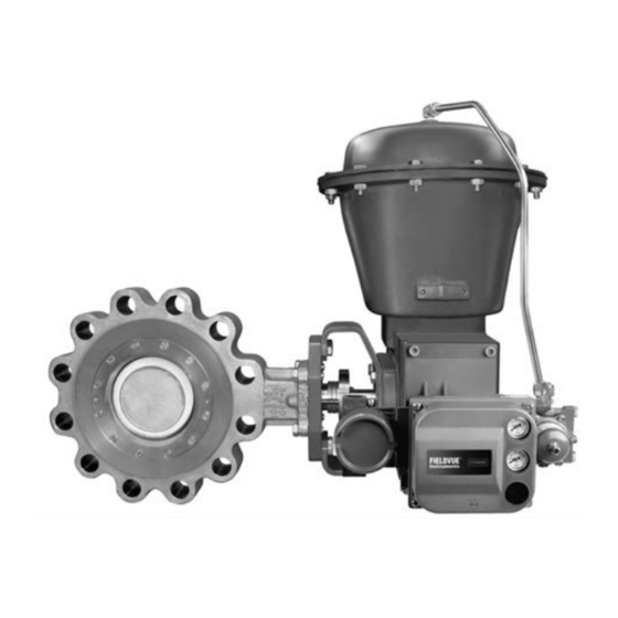
Figure 1. Fisher A11 Valve
1
1
2
2
4
5
5
6
7
9
10
11
11
14
15
16
17
18
19
W9570−1
20
20
Emerson sales office
or Local Business
A11 Valve
August 2017
Advertisement
Table of Contents

Related Manuals for Emerson Fisher A11


Summary of Contents for Emerson Fisher A11
-
Page 1: Table Of Contents
To avoid personal injury or property damage it is important to carefully read, understand, and follow all of the contents of this manual, including all safety cautions and warnings. If you have any questions about these instructions, contact your Emerson sales office or Local Business Partner before proceeding. -
Page 2: Description
Specifications are listed in table 1 and the specifications for a given valve are stamped on a nameplate attached to the valve. Educational Services For information on available courses for the A11 High Pressure valve, as well as a variety of other products, contact: Emerson Automation Solutions Educational Services - Registration Phone: 1-641-754-3771 or 1-800-338-8158 E-mail: education@emerson.com... - Page 3 CTFE: 10% of Class IV Available Configurations CTFE with Aluminum Backup Ring: Class VI Valve Sizes Consult Emerson sales office for other shutoff : Size J 3, J 4, J 6, J 8, (1) (2) Class 900 and 1500 classifications J 10, J 12, J 14, J 16, J 18, J 20 and J 24‐inch...
-
Page 4: Installation
When installing a valve after it has been in long‐term storage, cycle the valve at least ten times to re‐energize the dynamic seal. Please contact your Emerson sales office or Local Business Partner if you have any questions about preparing a valve for storage or... -
Page 5: Adjusting The Travel Stops
Instruction Manual A11 Valve August 2017 D104223X012 Adjusting the Travel Stops CAUTION When using manual or power actuators, adjust the actuator travel stops so the disk stop in the valve body does not absorb the output of the actuator. For actuators without travel stops, the actuator must be properly mounted to prevent it from driving the valve disk against the valve disk travel stop. -
Page 6: Valve Orientation
For metal‐seated and cryogenic valve gasket recommendations, please contact your Emerson sales office. 4. Refer to the appropriate table for the quantity and size of flange bolts required (table 3) and proceed with the following instructions. -
Page 7: Installing The Valve
If the two pressures are equal, then the one lasting the longest period of time should be applied to the preferred side. A flow tag with an arrow is provided for proper installation. If you have questions about proper valve orientation in a specific application, contact your Emerson sales office Local Business Partner. Installing the Valve... - Page 8 Because some valve/body trim material combinations are limited in their pressure drop and temperature ranges, do not apply any other conditions to the valve without first contacting your Emerson sales office or Local Business Partner. Figure 3. Proper Installation Procedure...
-
Page 9: Packing Adjustment And Shaft Bonding
Instruction Manual A11 Valve August 2017 D104223X012 Packing Adjustment and Shaft Bonding WARNING Personal injury could result from packing leakage. Valve packing was tightened before shipment; however, the packing might require some readjustment to meet specific service conditions. Check with your process or safety engineer for any additional measures that must be taken to protect against process media. -
Page 10: Maintenance
Instruction Manual A11 Valve August 2017 D104223X012 Figure 4. Optional Shaft‐to‐Body Bonding Strap Assembly ACTUATOR VALVE BODY 37A6528‐A VIEW A‐A A3143‐2 Maintenance Valve parts are subject to normal wear and must be inspected and replaced as necessary. The frequency of inspection and replacement depends upon the severity of service conditions. -
Page 11: Removing The Valve
Instruction Manual A11 Valve August 2017 D104223X012 Removing the Valve WARNING Using the procedures listed in the above WARNING, loosen the flange bolting that holds the valve. Make sure the valve cannot slip or twist while the bolting is being loosened and removed. For field repair, remove the valve from the pipeline. - Page 12 Instruction Manual A11 Valve August 2017 D104223X012 Figure 5. Standard Packing Configurations STANDARD PACKING PTFE V‐RING GE71528-A GRAPHITE RIBBON GE71524-A GE40118‐A GE40113‐A SINGLE PTFE PACKING GRAPHITE PACKING ENVIRO‐SEAL PACKING Note: With conductive packing, the female adaptor in PTFE v-ring packing is carbon -filled PTFE.
- Page 13 Instruction Manual A11 Valve August 2017 D104223X012 Figure 6. 7-Ring, Reverse, Leak-off, and Lubricated Packing Configurations THE FOLLOWING PACKING CONFIGURATIONS ARE AVAILABLE FOR SPECIFIC APPLICATIONS: CODE 5: GRAPHITE CODE 1: PTFE STANDARD ON SOFT SEATED AND CRYOGENIC VALVES CODE 6: PTFE STANDARD 'V' STANDARD SQUARE TYPE PACKING...
-
Page 14: Seal Maintenance
Instruction Manual A11 Valve August 2017 D104223X012 Seal Maintenance 1. After the valve has been removed from the line and the manual or power actuator has been removed, manually rotate the shaft (key 4) counter‐clockwise until the disk has moved a full 180_. -
Page 15: Soft Seal Installation
Instruction Manual A11 Valve August 2017 D104223X012 CAUTION In the following step, use the appropriate tool to avoid damage to the seal or T‐slot area of the valve. 4. Different valve types have different seal designs and components. To see the appropriate seal, refer to figure 7. Insert the appropriate tool under the top edge of seal and gently pry the seal out. -
Page 16: Metal And Phoenix Iii Seal Installation
Instruction Manual A11 Valve August 2017 D104223X012 Seal Installation For HPS seal installation: Locate the replacement seal ring (key 8) and note the shape of the ring. The ring is wider across one edge diameter and narrower across the other edge diameter as shown in figure 8. Around the outside circumference is one wide groove. Install the seal ring (key 8) into the valve body by first placing the wider outside diameter of the seal ring into the T‐slot area of the valve body which is shown in figure 9. -
Page 17: Cryogenic Seal Installation
Instruction Manual A11 Valve August 2017 D104223X012 CAUTION This gasket is a thin graphite material. Take care to avoid damaging the gasket. However, punch one initial screw hole through the gasket for alignment purposes. 4. Install the retaining ring and align the screw holes in the retaining ring with the holes in the valve body. Install the first retaining ring screw through the punched hole in the ring gasket. -
Page 18: Valve Shaft/Disk Pin Unit Maintenance
Instruction Manual A11 Valve August 2017 D104223X012 4. Install the retaining ring and align the screw holes in the retaining ring with the holes in the valve body. Install the first retaining ring screw through the punched hole in the ring gasket. Install the other ring screws by pushing the screws through the graphite gasket and threading them into the screw holes in the valve body. -
Page 19: Bearing Maintenance
Instruction Manual A11 Valve August 2017 D104223X012 7. Extract the shaft (key 4) by hand‐pulling or by using the pin extractor screwed into the end of the shaft. Table 4. Torque Values for Fasteners Fastener InSlb FtSlb Nominal Size ‐ ‐ ‐ ‐... -
Page 20: Parts Ordering
Use only genuine Fisher replacement parts. Components that are not supplied by Emerson Automation Solutions should not, under any circumstances, be used in any Fisher instrument. The use of components not manufactured by Emerson Automation Solutions may void your warranty, might adversely affect the performance of the instrument, and could result in personal injury or property damage. - Page 21 Instruction Manual A11 Valve August 2017 D104223X012 Figure 10. Typical Fisher A11 Valve Assembly PACKING HEX NUTS PACKING FLANGE PACKING FOLLOWER PACKING SET SHAFT, PACKING STUDS UPPER BEARING BODY THURST BEARING VALVE GASKET DISK SEAL RING SHAFT/DISK PINS RETAINING RING...
- Page 22 Instruction Manual A11 Valve August 2017 D104223X012...
- Page 23 Instruction Manual A11 Valve August 2017 D104223X012...
- Page 24 ENVIRO‐SEAL and Fisher are marks owned by one of the companies in the Emerson Automation Solutions business unit of Emerson Electric Co. Emerson Automation Solutions, Emerson, and the Emerson logo are trademarks and service marks of Emerson Electric Co. All other marks are the property of their respective owners.
Need help?
Do you have a question about the Fisher A11 and is the answer not in the manual?
Questions and answers