Advertisement
Available languages
Available languages
Quick Links
General information and technical data:
• Refrigerants: see nameplate
• Evaporating Temperature Range:
a) for valves with pressure limitation (MOP): see
nameplate
b) for valves without pressure limitation:
+30° C to -45° C
• Max. Working Pressure PS: 31 bar
• Safe Working Temperature: 80° C
• Marking:
!
Safety instructions:
• Read installation instruction thoroughly. Failure
to comply can result in device failure, system
damage or personal injury.
• It is intended for use by persons having the
appropriate knowledge and skill. Before opening
any system make sure pressure in system is
brought to and remains at atmospheric pressure.
Do not leak any refrigerant into the atmosphere.
• Do not use on service conditions or fluids not
specifically cataloged, without prior approval of
Alco Controls.
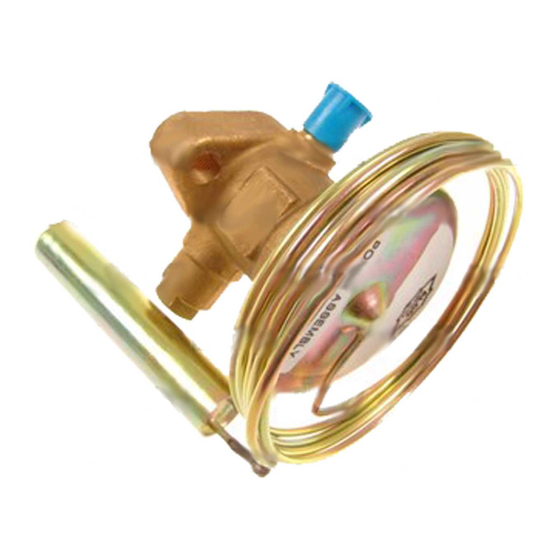
Installation: (Fig. 1)
1 Power Assembly
2 Remote Bulb
3 External Equalizer
Connection
4 Seal Cap
10 Cap Screws
5 Body Flange Gasket
11 Lugged Spring
6 Cage Assembly
1. Valves may be installed in any position, but should
be located as close as possible to distributor or
evaporator inlet.
Emerson Climate Technologies GmbH
Am Borsigturm 31 I 13507 Berlin I Germany
Thermo® Expansion Valves
TCLE, TJRE, TERE, TIRE, THRE
2. Install line connections to valve so its flow arrow
corresponds to flow direction on flange. On valves
with solder connections remove cap screws, power
assembly, cage assembly and gaskets prior to
brazing.
3. Assemble valve after brazing, according to Fig 1,
making sure that lugs of spring carrier line up with
slots inside power assembly.
4. Tighten cap screws evenly to torque specification
35 Nm. Overtorqueing may result in valve body
damage.
5. Attach remote bulb to suction line as close to
evaporator outlet as possible in a horizontal run and
fix it, normally at the 4 or 8 o'clock position. Clean
surface of suction line before.
6. Connect one end of external equalizer line (OD = 6
mm = ¼ inch) to valve. Connect other end to
suction line slightly downstream from remote bulb
location and position it so that it cannot syphon oil
from the suction line.
7. Check for leaks, sufficient system refrigerant and
be sure no flash gas is present.
Superheat Adjustment: (Fig. 2)
ALCO Thermo
for optimum superheat settings. This setting should be
modified
7 Body Flange
readjustment should be at the lowest expected
Gasket
evaporating temperature:
8 Seat Gasket
1. Remove seal cap (1) on side of valve.
9 Body Flange
2. Turn
superheat and counter-clockwise to decrease it.
Allen key X 99999 (2).
Carrier
3. Reinstall seal cap. Wait 20 minutes before further
adjustments.
4. If refrigerant escapes use allen key X99999 (3) to
fix spindle gasket.
www.emersonclimate.eu
Operating instruction
-Expansion Valves are factory preset
only
if
absolutely
necessary.
adjusting
stem clockwise to
Date: 29.06.2016
Pressure
Valve
Refri- changes +10
Series gerant per turn
(bar)
R 134a
0,05
R 22
0,05
TCLE R 404A
0,05
R 407C
0,05
R 507
0,05
TJRE R 134a
0,038
TERE, R 22
0,038
TIRE, R 404A
0,038
THRE R 407C
0,038
R 507
0,038
Note:
1. Foreign particles in Thermo
diaphragm failure, flooding or starving. Use of an
ALCO Filter Drier is strongly recommended.
2. Protect valve against excessive vibrations as it may
result in bulb tubing breaking.
Leakage test:
After completion of installation, a test pressure must
be carried out as follows:
- According to EN378 for systems which must
comply with European pressure equipment directive
97/23/EC
- To maximum working pressure of system for other
The
applications
Warning:
• Failure to do so could result in loss of
increase
refrigerant and personal injury.
• The pressure test must be conducted by skilled
persons with due respect regarding the danger
related to pressure.
T_S_OI_ML_R06_862157.docx
Evaporating temperature °C
0
-10
-20
-30
-40
Static superheat changes
per turn of stem (K)
0,4
0,5
0,6
0,9
0,3
0,3
0,4
0,5
0,7
1,0
0,2
0,3
0,3
0,4
0,6
0,8
0,2
0,3
0,4
0,6
0,2
0,3
0,3
0,4
0,5
0,7
0,3
0,4
0,5
0,7
0,2
0,3
0,3
0,4
0,5
0,7
0,2
0,2
0,3
0,3
0,5
0,6
0,2
0,2
0,3
0,4
0,2
0,2
0,2
0,3
0,4
0,5
-Valve may cause
Advertisement

Subscribe to Our Youtube Channel
Related Manuals for Emerson Alco Controls TCLE


Summary of Contents for Emerson Alco Controls TCLE
- Page 1 4. If refrigerant escapes use allen key X99999 (3) to be located as close as possible to distributor or fix spindle gasket. evaporator inlet. Emerson Climate Technologies GmbH www.emersonclimate.eu Am Borsigturm 31 I 13507 Berlin I Germany Date: 29.06.2016 T_S_OI_ML_R06_862157.docx...
- Page 2 3. Hutmutter wieder aufsetzen. Vor einer weiteren dem Durchflußpfeil auf dem Ventilflansch überein- Veränderung Einstellung mindestens 20 stimmt. Bei Ventilen mit Lötanschlüssen vor dem Minuten warten. Emerson Climate Technologies GmbH www.emersonclimate.eu Am Borsigturm 31 I 13507 Berlin I Germany Date: 29.06.2016 T_S_OI_ML_R06_862157.docx...
- Page 3 2. Raccordez les conduites à la base du détendeur de façon à ce que la direction du fluide corresponde avec la flèche sur la base. Emerson Climate Technologies GmbH www.emersonclimate.eu Am Borsigturm 31 I 13507 Berlin I Germany Date: 29.06.2016...
- Page 4 X99999 (3) para fijar la junta del fluido en la dirección de este. En las válvulas con vastago conexiones para soldar, quite los tornillos de Emerson Climate Technologies GmbH www.emersonclimate.eu Am Borsigturm 31 I 13507 Berlin I Germany Date: 29.06.2016...
- Page 5 2. Saldare lo zoccolo facendo attenzione che la freccia minuti tra una regolazione e l'altra. stampigliata sullo zoccolo sia nella direzione del flusso del refrigerante. Non saldare con la valvola Emerson Climate Technologies GmbH www.emersonclimate.eu Am Borsigturm 31 I 13507 Berlin I Germany Date: 29.06.2016...
- Page 6 потока в трубопроводе совпадало с направлением, указанном на корпусе вентиля. У вентилей «под пайку» удалите перед установкой заглушки, силовой элемент, клапанный узел и прокладки. Emerson Climate Technologies GmbH www.emersonclimate.eu Am Borsigturm 31 I 13507 Berlin I Germany Date: 29.06.2016 T_S_OI_ML_R06_862157.docx...
- Page 7 TCLE, TJRE, TERE, TIRE, THRE Fig. 1: Fig. 2: > 10 Nm < 15 Nm < 15 Nm Emerson Climate Technologies GmbH www.emersonclimate.eu Am Borsigturm 31 I 13507 Berlin I Germany Date: 29.06.2016 T_S_OI_ML_R06_862157.docx...
Need help?
Do you have a question about the Alco Controls TCLE and is the answer not in the manual?
Questions and answers