Table of Contents
Advertisement
Quick Links
Download this manual
See also:
User Manual
Advertisement
Table of Contents

Subscribe to Our Youtube Channel
Related Manuals for Photron FASTCAM SA3


Summary of Contents for Photron FASTCAM SA3
- Page 1 FASTCAM SA3 Hardware Manual Revision 1.00E...
- Page 2 ・This manual was created taking every possible measure to ensure the accuracy of its contents. However, if you find a questionable section, a mistake, or an omission, please contact Photron Limited using the contact information provided at the end of the manual. ・PHOTRON LIMITED is not responsible for the aftermath of the results of using the product or from following the instructions in this manual.
- Page 3 This manual contains the operating instructions and warnings necessary for using the system. Before using the system, please read the entire manual. If any part of this manual is unclear, contact Photron using the contact information printed at the back of the manual.
- Page 4 Chapter 5. Connecting a PC This chapter explains the procedure for connecting the system to a PC. Refer to the “Photron FASTCAM Viewer User’s Manual” for additional details on using a PC to control the system. Chapter 6. Specifications ...
- Page 5 In order to prevent injury to yourself and others, and to prevent damage to property, carefully observe the following safety precautions. Photron has given its full attention to the safety of this system. However, the extent of damage and injury potentially caused by ignoring the content of the safety precautions and using the system incorrectly is explained next.
- Page 6 Warning ■Do not perform actions that will damage the AC cable or plug. (Do not damage the cable, modify it, use it near a heater, excessively bend, twist or pull on it, place heavy objects on it, or bundle it.) Using the cable when damaged can cause fire, electric shock, or a short circuit.
- Page 7 ■When shipping, remove the connecting cable and use the original packaging or a dedicated carrying case. Do not ship the equipment in an environment where the temperature goes below -20°C or higher then 60°C. Also, prevent condensation from forming during shipment FASTCAM SA3 Hardware Manual...
- Page 8 MEMO...
-
Page 9: Table Of Contents
3.1.2. Saving Calibration Settings ..................32 3.1.3. Loading Calibration Settings ..................32 3.2. Selecting the Frame Rate ....................33 3.3. Selecting the Resolution....................35 3.4. Selecting the Shutter Speed..................... 37 3.4.1 Setting the Shutter Speed................... 37 3.4.2 Changing SHUTTER MODE..................39 FASTCAM SA3 Hardware Manual... - Page 10 3.13. Outputting External Trigger Signals................. 62 3.13.1. Outputting an External Synchronization Signal............63 3.14. Signal Delay ........................65 3.15. Event Marker Function....................67 3.16. Synchronizing Multiple FASTCAM SA3 Systems............. 68 3.17. Synchronizing the System with Other External Devices ..........73...
- Page 11 6.1.5. Recordable Image Count/Resolution ............... 107 6.1.6. Shutter Speed List ....................108 6.2. Dimensions ........................109 6.2.1 Camera Body ......................109 Chapter 7. Warranty....................... 111 7.1. About the Warranty ......................112 Chapter 8. Contacting Photron....................113 8.1. Contacting Photron ......................114 FASTCAM SA3 Hardware Manual...
- Page 12 MEMO...
-
Page 13: Chapter 1. Overview
Chapter 1. Overview 1.1. Product Overview and Features FASTCAM SA3 Hardware Manual... -
Page 14: Product Overview And Features
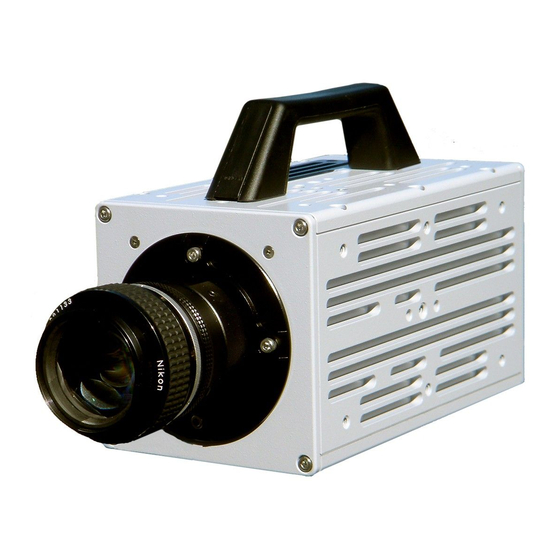
Chapter 1. Overview 1.1. Product Overview and Features The FASTCAM SA3 is a powerful engineering tool for use in research and development, design, production, and quality control, and in numerous fields such as science, medicine, biology, aviation and space. The system features superior basic performance with megapixel resolution, an ultra-sensitive image sensor capable of clear recording in low-light, and an ultra-high speed frame rate of a maximum of 120,000 fps. -
Page 15: Chapter 2. Setup
Chapter 2. Setup 2.1. System Components and Accessories 2.2. Part Names 2.3. Device Connections FASTCAM SA3 Hardware Manual... -
Page 16: System Components And Accessories
1 each F Mount Lens Cap (body integrated) I/O Cable FASTCAM Series Setup Disk (Driver/Application CD) FASTCAM SA3 Hardware Manual (This Manual) Photron FASTCAM Viewer User’s Manual Making a Gigabit Ether Connection (Simple Procedure Manual) Warranty Card Gigabit Ether Interface Cable (LAN Cable) -
Page 17: Accessories/Options
There are a total of eight models according to the combination of options. The models are listed below. Max. Frame Rate Sensor Type Memory Model Name FASTCAM SA3 model 120K-C1 Color FASTCAM SA3 model 120K-C2 120,000 fps FASTCAM SA3 model 120K-M1... -
Page 18: Part Names
2.2. Part Names The system is composed of components including the camera body, AC power supply, and the "Photron FASTCAM Viewer" controls software (referred to below as PFV). ·For each of the system components, ·Do not expose to shock outside of specifications. -
Page 19: Camera Body Part Names
2.2.2 Camera Body Part Names Handle Front F Mount Rear Status Display LEDs Gigabit Ethernet LAN cable Connector Power Switch I/O Port Connector KEYPAD Connector DC22-32V 60VA Power Supply Connector Video Output Connector FASTCAM SA3 Hardware Manual... -
Page 20: Status Display Leds On The Rear Of The Camera Body
Chapter 2. Setup 2.2.3 Status Display LEDs on the Rear of the Camera Body There are a number of LEDs on the rear of the system's camera body. These LEDs indicate the status of the system. The meaning of each LED is explained here. ■MAIN LEDs POWER (Green) ... - Page 21 REC READY (Yellow) LED ON: Ready to record LED FLASHING: ENDLESS recording ("REC" LED also simultaneously flashes) LED OFF: Not ready to record REC (Red) LED FLASHING: Recording LED OFF: Not recording FASTCAM SA3 Hardware Manual...
-
Page 22: Interchangeable Lens Mounts
Chapter 2. Setup 2.2.4 Interchangeable Lens Mounts The lens mount on the system can be changed according to the recording application. There are three types of interchangeable lens mounts, "Nikon F Mount", "C Mount", and "Photo-Sonics Mount" (optional). How to change lens mounts (Nikon F Mount → C Mount) ■... -
Page 23: Lcd Remote Controller (Optional)
Signal Name Connector Model Name Connector Model Name Body Connector Name (Maker) (Maker) PT02A-12-10S (023) PT06A-12-10P (023) KEYPAD Keypad Signal (Amphenol) (Amphenol) * The LCD remote controller is optional. It is not included in the standard configuration. FASTCAM SA3 Hardware Manual... -
Page 24: Serial Control
The system supports with serial control via an RS-422 connection through the KEYPAD connector. Serial control commands are available as separate list of commands. Please contact Photron or the store where the system was purchased about the command list. (See: 8.1 Contacting Photron) A cable is also not offered as an accessory. -
Page 25: I/O Port Connector
Use extreme caution as there is a risk of damage to both devices, the input device and the output device. For signals that can be input, see “3.12. Input/Output Signal Types”. I/O PORT (Camera Body) PT02A-16-26P (023) FASTCAM SA3 Hardware Manual... - Page 26 Chapter 2. Setup Connector Camera Body Cable Connector Input Signal Name Name Connector Model Model Name [Maker] Connector TRIG TTL IN TRIG TTL OUT TRIG SW IN SYNC IN GENERAL IN GENERAL OUT1 GENERAL OUT2 RESERV ED RESERV ED RESERV ED RESERV ED RESERV ED PT02A-16-26P(023)
-
Page 27: Dc 22-32V 60Va Power Supply Connector
Do not use a power supply which does not meet the system’s specifications, or a power supply you cannot guarantee the safety of. By using a power supply outside of the system specifications, not only is there the danger of the system malfunctioning, but also of fire and electric shock. FASTCAM SA3 Hardware Manual... -
Page 28: Device Connections
Chapter 2. Setup 2.3. Device Connections 2.3.1 Connecting a Video Monitor A video monitor connected to the camera controller can be used to check the live image (Camera Pass - through image). Connect the video input connector according to the video signal type of the monitor to display to the “VIDEO OUT”... -
Page 29: Connecting The Ac Power Supply
Connect the AC power supply unit to the “DC22-32V 60VA” connector on the rear of the camera body. ① Connect the AC cable to the AC power supply unit. ② Connect the AC cable to the power outlet. ③ FASTCAM SA3 Hardware Manual... -
Page 30: Connecting The Lcd Remote Controller (Optional)
Chapter 2. Setup 2.2.3 Connecting the LCD Remote Controller (Optional) If you have the optional LCD remote controller, connect it by plugging the LCD remote controller connector into the connector terminal labeled “KEYPAD” on the rear of the camera body. Refer to the “LCD Remote Controller User’s Manual”... -
Page 31: Connecting A Pc
1000BASE-T specification, up to 100 m. One PC can connect to a maximum of 64 Photron Gigabit Ether interface equipped cameras using a hub. When connecting multiple devices, connect through a switching hub that can connect at 1000BASE-T. The maximum length of the cable that connects the system (or PC) to the switching hub is also 100 m. - Page 32 MEMO...
-
Page 33: Chapter 3. Recording
3.12. Using External Triggers 3.13. Using External Synchronization Signals 3.14. Signal Delay 3.15. Event Marker Function 3.16. Synchronizing Multiple FASTCAM SA3 Systems (Multiple Unit Synchronized Recording) 3.17. Synchronizing the System with Other External Devices (Frame Rate Synchronized Recording) 3.18. Synchronizing the System with Other Cameras... -
Page 34: Image Initialization (Calibration)
These phenomena can be resolved by executing calibration again. 3.1.1. Executing Calibration Calibration is executed from the "LCD remote controller (optional)" or from PFV. Refer to the "LCD Remote Controller User's Manual" or the "Photron FASTCAM Viewer User's Manual" for the calibration procedure. 3.1.2. Saving Calibration Settings The black image data for correction use that was obtained by executing the calibration can be saved as one pattern internally on the system. -
Page 35: Selecting The Frame Rate
If the system is in a mode other than LIVE mode, check "Live" on the camera control panel. Select the frame rate from "Frame Rate" on the camera control panel. ② When you change the frame rate, the "Live Info" display in the upper left of the screen also changes. ③ FASTCAM SA3 Hardware Manual... - Page 36 Chapter 3. Recording For the LCD Remote Controller (Optional) Verify that the camera mode is in LIVE mode (the image displayed is passed through from the camera). ① If the system is in a mode other than LIVE mode, press the LIVE key on the LCD remote controller. When the system is in LIVE mode, the LIVE key LED illuminates.
-
Page 37: Selecting The Resolution
If the system is in a mode other than LIVE mode, check "Live" on the camera control panel. Select the resolution from "Resolution" on the camera control panel. ② When you change the frame rate, the "Live Info" display in the upper left of the screen also changes. ③ FASTCAM SA3 Hardware Manual... - Page 38 Chapter 3. Recording For the LCD Remote Controller (Optional) Verify that the camera mode is LIVE mode. ① Verify the monitor's upper display is "LIVE" Press the LCD remote controller's RESOLUTION ▲ or ▼ key. Pressing the ▲ key raises the resolution ②...
-
Page 39: Selecting The Shutter Speed
If the system is in a mode other than LIVE mode, check "Live" on the camera control panel. Select the shutter speed from "Shutter Speed" on the camera control panel. ② When you change the frame rate, the "Live Info" display in the upper left of the screen also changes. ③ FASTCAM SA3 Hardware Manual... - Page 40 Chapter 3. Recording For the LCD Remote Controller (Optional) Verify that the camera mode is LIVE mode. ① Verify the monitor's upper display is "LIVE" Press the LCD remote controller's SHUTTER ▲ or ▼ key. Pressing the key raises the shutter speed in ②...
-
Page 41: Changing Shutter Mode
* The amount of adjustment is expressed as %. For the strength of the adjustment, 0% is no adjustment, 95% is the maximum effect. When using the DS SHUTTER function on a color model, there are situations where the colors become unbalanced and the color reproducibility degrades. FASTCAM SA3 Hardware Manual... -
Page 42: Selecting The Trigger Mode
Chapter 3. Recording 3.5. Selecting the Trigger Mode With the system, in order to reliably capture high-speed phenomena, many kinds of trigger modes have been made available. These trigger modes are explained next. There are five types of trigger modes which are listed below. ・START ・CENTER ・END ・MANUAL ・RANDOM For PFV (Standard) Verify that the camera mode is in LIVE mode (the image displayed is passed through from the camera). - Page 43 The selected mode will be displayed on the screen immediately. Verify that the trigger mode display on ③ the screen changes each time the key is pressed. The trigger mode display changes in the upper part of the monitor FASTCAM SA3 Hardware Manual...
-
Page 44: Start Mode
Chapter 3. Recording 3.5.1. START Mode START mode is a trigger mode where recording starts the instant the trigger is input, the scene is recorded until the memory is full, and then recording ends. This mode is suitable for taking images of high-speed phenomena when what will happen, and when it happens, is known in advance. -
Page 45: End Mode
75% after the REC key is pressed as shown in the diagram below. For example, in a situation with a maximum record time of two seconds, 0.5 seconds before and 1.5 seconds after the trigger is input are recorded and saved, a total of two seconds of high-speed video. FASTCAM SA3 Hardware Manual... -
Page 46: Random Mode
Chapter 3. Recording 3.5.5. RANDOM Mode RANDOM mode is a trigger mode where each time a trigger is input only a predetermined number of frames are saved to memory. For example, this function is convenient for a subject which is an irregular and repeated phenomenon which can have a trigger output produced for each cycle or occurrence. -
Page 47: White Balance Adjustment (Color Models Only)
The values set here are stored in the camera body’s internal memory as the user preset, and they can be loaded by selecting USER. 3.7. Color Enhancement Function (Color Models Only) Color models feature an image color enhancement setting. The image color enhancement level can be adjusted in five steps, including the OFF setting. FASTCAM SA3 Hardware Manual... - Page 48 Chapter 3. Recording For PFV (Standard) Verify that the camera mode is in LIVE mode (the image displayed is passed through from the camera). ① If the system is in a mode other than LIVE mode, check "Live" on the camera control panel. Select color adjust on the left tree from "Camera Option"...
- Page 49 Sets x1 color enhancement MODE3 Sets x1.5 color enhancement MODE4 Sets x2 color enhancement Use the LCD remote controller's keys to select one of the modes listed above. When finished, press ④ the ENTER key to complete the setting. FASTCAM SA3 Hardware Manual...
-
Page 50: Lut (Look-Up Table) Operations
Chapter 3. Recording 3.8. LUT (Look-Up Table) Operations The LUT (Look-Up Table) refers to a reference table that defines the relationship between the pixel brightness gradation of the original image data taken and the brightness gradation displayed on a computer screen or video monitor. -
Page 51: Using Preset Lut Patterns
Six preset LUT patterns have been prepared in advance on the system. Each of these patterns is explained in sequence in this section. D1: GAIN 1x The input is always linear output. This LUT is used for normal conditions. D2: Gamma 0.6 This LUT is 0.6 gamma correction. FASTCAM SA3 Hardware Manual... - Page 52 Chapter 3. Recording D3: Gamma 0.45 This LUT is 0.45 gamma correction. D4: Gain 2x The gain is doubled and you can display the dark areas of the image emphasized. D5: Gain 4x The gain is quadrupled and you can display the dark areas of the image emphasized. This LUT emphasizes the dark portions even more than D4.
-
Page 53: Using A Custom Lut
D6: Reverse Gradation The input gradation is reversed and then displayed. 3.8.2. Using a Custom LUT Creating a LUT pattern is done with PFV. For details, refer to the “PHOTRON FASTCAM Viewer User’s Manual”. 3.9. Edge Enhancement Function With the system's edge enhancement setting, you can enhance the edges in the recorded image in three steps. -
Page 54: Partition Memory & Record
Chapter 3. Recording 3.10. Partition Memory & Record The system contains internally 2 GB standard, or a maximum of 4 GB, of high-capacity memory for recording use. This recording memory can be partitioned and assigned to each recording. Memory is partitioned into equal sizes and a maximum of 8 partitions can be set. - Page 55 Select partition on the left tree from "Camera Option" on the camera control panel. ② Decide the number of partitions by changing "Number". ③ FASTCAM SA3 Hardware Manual...
- Page 56 Chapter 3. Recording For the LCD Remote Controller (Optional) ① Press the LCD remote controller's MENU key and the menu list will display. ② Select PARTITION SETUP from the PARTITION submenu with the ARROW keys on the LCD remote controller and press the ENTER key. ③...
-
Page 57: Record To A Partitioned Section
Use the LCD remote controller's ↑↓ keys to select the section ID you wish to record to. Verify the ID ① display on the screen. ↑ Select ID Down ↓ When the section ID you wish to record to is set, record following the normal recording procedure. ② FASTCAM SA3 Hardware Manual... -
Page 58: Recorded Section Playback
Chapter 3. Recording 3.10.3 Recorded Section Playback The images recorded to each partition section can be played by selecting the section ID. For PFV (Standard) Verify that the camera mode is in MEMORY mode (an image in the camera's memory is displayed). If ①... -
Page 59: Partition Mode
This mode saves the effort moving to the IDs by hand and putting the system into the trigger wait state, so it is better suited for consecutive recordings while moving the IDs. MODE2 operation is only valid when the trigger mode is the following modes. START, CENTER, END, MANUAL FASTCAM SA3 Hardware Manual... -
Page 60: Input/Output Signal Types
Chapter 3. Recording 3.11. Input/Output Signal Types With the system, many signals can be input and output through the I/O cable. Signals that can be input and output from the I/O cable are listed below. A signal other than the specified signal must not be input to the various connectors. Use extreme caution as there is a risk of damage to both devices, the input device and the output device. -
Page 61: General In Connector
:Outputs the camera's exposure period signal. Outputs during both LIVE and recording. REC POS/NEG :Outputs an interval signal during recording. TRIG POS/NEG :Outputs the trigger signal the camera received. READY POS/NEG :Outputs a signal that indicates the recording ready state. FASTCAM SA3 Hardware Manual... -
Page 62: Using External Triggers
Chapter 3. Recording 3.12. Using External Triggers With the system, you can record by receiving various trigger signals matched to the recording application. The trigger signals that can be used with the system are explained here. The external trigger signals that can be used with the system and their input system are listed below. Set the external trigger signal input by selecting SYNC IN/OUT from the "LCD remote controller (optional)"... - Page 63 390ΩF IN2- 0.1μF SIGNAL_GND GE NERAL TTL IN Circuit Diagram IL611-3 390ΩF IN1+ SYNC SYNC_IN IN1- OUT1 IN2+ OUT2 GENERAL_IN IN2- GENERAL 390ΩF 0.1μF SIGNAL_GND TRIG SW IN Circuit Diagram MICROSD150-02 NFW31SP506X1E4 TRIG_SW__IN TRIG_SW 220ΩF 0.1μF FASTCAM SA3 Hardware Manual...
-
Page 64: Outputting External Trigger Signals
Chapter 3. Recording 3.13. Outputting External Trigger Signals With the system, you can externally output trigger signals. Output is performed with the TRIG TTL OUT connector’s dedicated trigger output system provided by the system, and additionally, output can also be optionally set from the GENERAL OUT connector. -
Page 65: Outputting An External Synchronization Signal
If the system is in a mode other than LIVE mode, check "Live" on the camera control panel. Select I/O on the left tree from "Camera Option" on the camera control panel. Set "GENERAL OUT1". FASTCAM SA3 Hardware Manual... - Page 66 Chapter 3. Recording For the LCD Remote Controller (Optional) Press the LCD remote controller's MENU key and the menu list is displayed. ① Select GENERAL OUT1 (When setting the GENERAL OUT2 connector, GENERAL OUT2) from the ② SYNC IN/OUT submenu with the LCD remote controller's ARROW keys. The menu is displayed.
-
Page 67: Signal Delay
Select signal delay settings on the left tree from "Camera Option" on the camera control panel. Set each item. For the LCD Remote Controller (Optional) TRIG TTL IN DELAY Setting Range: 0-60 (s), in 100 ns units Set from the menu, SYNC IN/OUT submenu, TRIG TTL IN DELAY. FASTCAM SA3 Hardware Manual... - Page 68 Chapter 3. Recording From the instant the trigger signal is input to the FASTCAM SA3, the system will recognize the trigger input later than normal, after the specified amount of time set has elapsed. SYNC IN DELAY Setting Range: 0-1/frame rate (s), in 100 ns units Set from the menu, SYNC IN/OUT submenu, SYNC IN DELAY.
-
Page 69: Event Marker Function
· When connected to a video monitor, the screen text displays EVENT FRAME X when displaying an event frame. (Where X is a number from 1-10.) · When operating with PFV, event markers are displayed as green dots. Event Markers FASTCAM SA3 Hardware Manual... -
Page 70: Synchronizing Multiple Fastcam Sa3 Systems
Chapter 3. Recording 3.16. Synchronizing Multiple FASTCAM SA3 Systems (Multiple Unit Synchronized Recording) The system can perform synchronized recording by synchronizing multiple units using external Synchronization input/output. Conceptual Diagram of a Synchronized Connection CAMERA No.2 CAMERA No.1 (SLAVE) EXT-SYNC IN... - Page 71 If the system is in a mode other than LIVE mode, check "Live" on the camera control panel. Select I/O on the left tree from "Camera Option" on the camera control panel. ② Set "GENERAL OUT1". ③ FASTCAM SA3 Hardware Manual...
- Page 72 Chapter 3. Recording For the LCD Remote Controller (Optional) ① Press the LCD remote controller's MENU key and the menu list is displayed. ② Select GENERAL OUT1 from the SYNC IN/OUT submenu with the LCD remote controller's ARROW keys and press the ENTER key. From the menu, select the signal to output from the master camera’s GENERAL OUT1 connector.
- Page 73 If the system is in a mode other than LIVE mode, check "Live" on the camera control panel. Select I/O on the left tree from "Camera Option" on the camera control panel. ② Set SYNC IN to "ON CAM POS". ③ FASTCAM SA3 Hardware Manual...
- Page 74 Chapter 3. Recording For the LCD Remote Controller (Optional) Input the slave camera’s synchronization. Connect the slave camera’s SYNC IN connector with the ① master camera’s GENERAL OUT1 connector using a BNC cable. When the synchronization signal is input to the SYNC IN connector, the SYNC IN LED (yellow) on the rear of the slave camera illuminates.
-
Page 75: Synchronizing The System With Other External Devices
When conducting frame rate synchronization recording with the system, the signal that can be input must meet the following conditions. · TTL level, positive polarity or negative polarity · 60 Hz (50 Hz for PAL) to 150,000 Hz FASTCAM SA3 Hardware Manual... -
Page 76: System Settings
Chapter 3. Recording System Settings For PFV (Standard) Verify that the camera mode is in LIVE mode (the image displayed is passed through from the camera). ① If the system is in a mode other than LIVE mode, check "Live" on the camera control panel. Select I/O on the left tree from "Camera Option"... - Page 77 Output the signal from the synchronization device and verify that the system recognizes the output ⑦ frequency and synchronizes its frame rate. The recognized frame rate will display in the lower left of the video monitor. FASTCAM SA3 Hardware Manual...
- Page 78 Chapter 3. Recording The frequency of the synchronization signal cannot be changed during LIVE or recording. (This is out of spec assurance.) The synchronization signal can be changed if you repeat steps 1 through 3 after inputting the changed frequency. The system is reset. If no synchronization signal is input or the input signal is under 60Hz (50Hz) during steps 3-7, or the synchronization signal is lost, the display shows “NO SYNC...
-
Page 79: Synchronizing The System With Other Cameras
For camera models that can perform synchronized recording or for detailed instructions on making the settings, contact Photron at the contact information in “8.1. Contacting Photron”. FASTCAM SA3 Hardware Manual... - Page 80 MEMO...
-
Page 81: Chapter 4. Playback
Chapter 4. Playback 4.1. Video Playback 4.2. Fast-Forward and Fast-Reverse Playback 4.3. Single Frame Advance Playback 4.4. Enlarging and Shrinking the Playback Screen (Zoom, Fit, Scroll) 4.5. Segment of Interest Playback 4.6. Using the Playback Event Marker Function FASTCAM SA3 Hardware Manual... -
Page 82: Video Playback
Chapter 4. Playback 4.1. Video Playback The system can immediately playback images recorded to memory on a connected video monitor or on the LCD remote controller's LCD screen. This procedure is explained here. For PFV (Standard) Verify that the camera mode is in MEMORY mode (an image in the camera's memory is displayed). If ①... - Page 83 ③ playback speed is displayed in the upper part of the screen. PAL output playback rate 2, 4, 8, 12, 25 fps NTSC output playback rate 2, 5, 10, 15, 30 fps Slow Fast ← → FASTCAM SA3 Hardware Manual...
-
Page 84: Fast-Forward And Fast-Reverse Playback
Chapter 4. Playback 4.2. Fast-Forward and Fast-Reverse Playback For PFV (Standard) Verify that the camera mode is in MEMORY mode (an image in the camera's memory is displayed). If ① the system is in a mode other than MEMORY mode, check "Memory" on the camera control panel. To play changing the playback speed, select the desired speed (fps) from "Speed"... - Page 85 ▐ ▌ playback. As an example, the display on the screen will be similar to the image shown below. ⑤ Playback Speed Frame Number Recording Time Trigger Mode Time from Trigger Point Number of Recorded Frames FASTCAM SA3 Hardware Manual...
-
Page 86: Single Frame Advance Playback
Chapter 4. Playback 4.3. Single Frame Advance Playback For PFV (Standard) · Click the "Frame Advance" button on the playback control panel. Reverse Frame Advance Frame Advance For the LCD Remote Controller (Optional) Setup: Set the camera to MEMORY mode. Press the PLAY key (). -
Page 87: Enlarging And Shrinking The Playback Screen (Zoom, Fit, Scroll)
Display the image in the view window set to the same pixel s ize as that of the PC screen. Automatically adjust the scaling of the display image to fit the image within the view window. FASTCAM SA3 Hardware Manual... - Page 88 Chapter 4. Playback For the LCD Remote Controller (Optional) Press the LCD remote controller's FIT/1:1 key. ① 640x480 NTSC 512x128 The video screen’s display size changes and the recording area is displayed at its maximum size ② on the screen. 640x480 NTSC 640x160 Press the FIT/1:1 key again to return to the original size.
-
Page 89: Displaying The Video Screen Enlarged (Zoom)
After clicking this button, select the optional scaling factor from the displayed list, and the display will be scaled by that factor. For the LCD Remote Controller (Optional) ③ Press the LCD remote controller's ZOOM key. FASTCAM SA3 Hardware Manual... -
Page 90: Scrolling The Video Screen
Chapter 4. Playback ④ The LCD remote controller's ZOOM key LED illuminates. The ZOOM message and the current zoom factor are also displayed in the upper right of the video output screen. With the ARROW keys, enlarge or shrink. The center of the image displayed on the screen is maintained while the image is enlarged or shrunk. - Page 91 The SCROLL message is displayed in the upper right of the video output screen. ② Scroll the screen with the ARROW keys. When the recording area is already fully displayed in the video ③ screen, scroll cannot be used. ↑ Down ↓ Right→ ←Left FASTCAM SA3 Hardware Manual...
-
Page 92: Segment Of Interest Playback
Chapter 4. Playback 4.5. Segment of Interest Playback The playback of images shot at high-speed takes an extraordinary amount of time. For example, when played back at a normal 30 fps, one second of video shot at high-speed at 2000 frames a second takes 66 seconds to playback, in other words, over one minute of playback time. - Page 93 Press the ON/OFF key in the SEGMENT PLAY BACK section of the LCD remote controller and verify that ⑤ the LED illuminates. This puts the system in segment playback mode. All of the normal playback operations described above will now occur only within the range specified by the start and end points. FASTCAM SA3 Hardware Manual...
-
Page 94: Using The Playback Event Marker Function
Chapter 4. Playback 4.6. Using the Playback Event Marker Function During MEMORY mode, you can store 10 playback image frame numbers and immediately access, or jump to, those stored frame numbers (event marker frames). By marking the desired position while the images are playing, this convenient function can easily recall those positions. - Page 95 When an event marker frame is displayed, “MARKER FRAME X” appears on the text on screen. (Where ⑥ X is a number between 1 and 10) When storing frames and going over 10 points, the frame numbers will be overwritten in order from the first stored. FASTCAM SA3 Hardware Manual...
- Page 96 MEMO...
-
Page 97: Chapter 5. Connecting A Pc
Chapter 5. Connecting a PC 5.1. Connecting the Gigabit Ether Interface to a PC FASTCAM SA3 Hardware Manual... -
Page 98: Connecting The Gigabit Ether Interface To A Pc
The maximum cable length between the PC and the system is, compliant to the 1000BASE-T specification, up to 100 m. One PC can connect to a maximum of 64 Photron Gigabit Ether interface equipped cameras using a hub. When connecting multiple devices, connect through a switching hub that can connect at 1000BASE-T. -
Page 99: Connecting The System And A Pc
NETMASK > 255.255.255.0 GATEWAY ADDRESS > 0.0.0.0 PORT > 2000 (Fixed, not changeable) 5.1.1. Connecting the System and a PC Connect the LAN cable to the system as shown below. *LAN cable plugged into the "GIGABIT ETHER" connector FASTCAM SA3 Hardware Manual... -
Page 100: Setting The Ip Address
Chapter 5. Connecting a PC 5.1.2. Setting the IP Address The procedure for setting the system’s IP address is shown below. Setting Procedure For PFV (Standard) "Device Information" is displayed with the [Help] menu – [Device Information…]. Select the camera and click the [IP Address/ID Setup] button. ①... - Page 101 Select DIGITAL I/F SET from the OTHERS submenu with the ARROW keys on the LCD remote ② controller and press the ENTER key. Use the ARROW ←→ keys to move the digit and the ↑↓ keys to set the IP address. ③ Press the ENTER key to confirm. ④ FASTCAM SA3 Hardware Manual...
-
Page 102: Using Dhcp (Dynamic Host Configuration Protocol)
Chapter 5. Connecting a PC 5.1.3. Using DHCP (Dynamic Host Configuration Protocol) The system is compatible with DHCP. In an environment where DHCP is used, the system’s IP address can be acquired from the DHCP server. The "LCD remote controller (optional)" is required for the settings. Setting Procedure ... -
Page 103: Connecting Multiple Systems And A Pc
Select the camera and click the [IP Address/ID Setup] button. ① Directly enter the IP address in "New Value" and click the [Change] button. ② After changing the IP address, shut down PFV and cycle the system's power. ③ FASTCAM SA3 Hardware Manual... - Page 104 Chapter 5. Connecting a PC For the LCD Remote Controller (Optional) Press the LCD remote controller's MENU key and the menu list is displayed. ① Select DIGITAL I/F SET from the OTHERS submenu with the ARROW keys on the LCD remote ②...
-
Page 105: Chapter 6. Product Specifications
Chapter 6. Product Specifications 6.1. Specifications 6.2. Dimensions FASTCAM SA3 Hardware Manual... -
Page 106: Specifications
Chapter 6. Product Specifications 6.1. Specifications 6.1.1. Product Specifications Image Sensor CMOS image sensor Sensor Resolution (full) 1024x1024 pixels Max. Full Frame Rate 2,000 fps (1024x1024) Max. Frame Rate 120,000 fps (128x16) Min. Frame Rate 60 fps (1024x1024) *PAL is 50 fps Sensor Size 17.4 mm x 17.4 mm Pixel Size... -
Page 107: General Specifications
AC Adapter 670 g Photron has verified two types of AC cables, type A (standard for Japan, USA, Canada, etc.) and type SE (standard for Germany, France, etc.). However, when those cables cannot properly receive power when plugged in, use the proper AC cable for the region’s standards and verify that AC cable works properly. -
Page 108: Frame Rate And Resolution
Chapter 6. Product Specifications 6.1.4. Frame Rate and Resolution FASTCAM SA3 model 120K Resolutio 1024 1024 1024 1024 1024 1024 1024 1024 Frame Rate 1024 1024 1024 1024 1024 ○ ○ ○ ○ ○ ○ ○ ○ ○ ○ ○... -
Page 109: Recordable Image Count/Resolution
6.1.5. Recordable Image Count/Resolution FASTCAM SA3 model 120K 2 GB Memory Model 4 GB Memory Model Resolution Frame Rate Rec. Time Rec. Frames Rec. Time Rec. Frames (seconds) (number) (seconds) (number) 1024 x 1024 2000 fps 0.681 1,361 1.363 2,726... -
Page 110: Shutter Speed List
Chapter 6. Product Specifications 6.1.6. Shutter Speed List Setting Value 1/ 2000 1/ 3000 1/ 3800 1/ 5000 1/ 6000 1/ 7500 1/ 10000 1/ 15000 1/ 20000 1/ 25000 1/ 30000 1/ 40000 1/ 50000 1/ 60000 1/ 75000 1/ 100000 1/ 120000 1/ 200000... -
Page 111: Dimensions
All dimensions are in millimeters (mm) – 25.4 mm equals one inch. These diagrams are not shown to scale. Front Side 261.07 253.47 37.67 65.62 6-M5 DEPTH 6 126.97 2-Φ5 DEPTH 140.97 145.62 1/4-20UNC DEPTH 6 154.97 225.62 Bottom FASTCAM SA3 Hardware Manual... - Page 112 Chapter 6. Product Specifications 6.2.2. AC Power Supply Unit All dimensions are in millimeters (mm) – 25.4 mm equals one inch. These diagrams are not shown to scale. 3000...
-
Page 113: Chapter 7. Warranty
Chapter 7. Warranty 7.1. About the Warranty FASTCAM SA3 Hardware Manual... -
Page 114: About The Warranty
Consumable goods (cables) ⑤ When repair, adjustment, or alternation done by an entity other than Photron service has been ⑥ performed on the system, or damage or malfunction that is determined to be attributed to a fault in the use the product. -
Page 115: Chapter 8. Contacting Photron
Chapter 8. Contacting Photron 8.1. Contacting Photron FASTCAM SA3 Hardware Manual... -
Page 116: Contacting Photron
For technical inquires related to the system, or for inquires related to the user’s manual, telephone, FAX, or e-mail Photron using the contact information listed below. In addition, the following items will be verified when inquiring, so note them in advance. - Page 117 FASTCAM SA3 Hardware Manual Publication Date April, 2008 Publisher PHOTRON LIMITED Chiyoda Fujimi Bldg., Fujimi 1-1-8, Chiyoda-ku, Tokyo 102-0071, JAPAN ©2007.PHOTRON LIMITED, All rights reserved. Printed in Japan. (Control No. E0804183581U)
Need help?
Do you have a question about the FASTCAM SA3 and is the answer not in the manual?
Questions and answers