Advertisement
Table of Contents
- 1 Table of Contents
- 2 Warning Decal Placement
- 3 Important Precautions
- 4 Before You Begin
- 5 Part Identification Chart
- 6 Assembly
- 7 93). Make Sure Not to Pinch the Upright Wire
- 8 The Chest Heart Rate Monitor
- 9 How to Use the Treadmill
- 10 How to Fold and Move the Treadmill
- 11 Maintenance and Troubleshooting
- 12 Exercise Guidelines
- 13 Part List
- 14 Exploded Drawing
- 15 Ordering Replacement Parts
- 16 Limited Warranty
- Download this manual
www.nordictrack.com
Model No. NTL22116.0
Serial No.
Write the serial number in the space
above for reference.
Serial Number
Decal
ACTIVATE YOUR
WARRANTY
To register your product and
activate your warranty today, go
to www.nordictrackservice.com/
registration.
CUSTOMER CARE
For service at any time, go to
www.nordictrackservice.com.
Or call 1-800-TO-BE-FIT
(1-800-862-3348)
Mon.–Fri. 6 a.m.–6 p.m. MT
Sat. 8 a.m.–12 p.m. MT
Please do not contact the store.
CAUTION
Read all precautions and instruc-
tions in this manual before using
this equipment. Save this manual
for future reference.
USER'S MANUAL
Advertisement
Table of Contents

Related Manuals for NordicTrack NTL22116.0


Summary of Contents for NordicTrack NTL22116.0
- Page 1 Model No. NTL22116.0 USER’S MANUAL Serial No. Write the serial number in the space above for reference. Serial Number Decal ACTIVATE YOUR WARRANTY To register your product and activate your warranty today, go to www.nordictrackservice.com/ registration. CUSTOMER CARE For service at any time, go to www.nordictrackservice.com.
-
Page 2: Table Of Contents
Apply the decal in the location shown. Note: The decals may not be shown at actual size. NORDICTRACK and IFIT are registered trademarks of ICON Health & Fitness, Inc. Google Maps is a trademark of Google Inc. The BLUETOOTH ®... -
Page 3: Important Precautions
5. The treadmill is intended for home use only. purchase a surge suppressor, see your local Do not use the treadmill in any commercial, NORDICTRACK dealer, call the telephone rental, or institutional setting. number on the front cover of this manual, or see your local electronics store. - Page 4 19. Always stand on the foot rails when starting 26. When folding or moving the treadmill, make or stopping the walking belt. Always hold the sure that the storage latch is holding the handrails while using the treadmill. frame securely in the storage position. Do not operate the treadmill while it is folded.
- Page 6 STANDARD SERVICE PLANS...
-
Page 7: Before You Begin
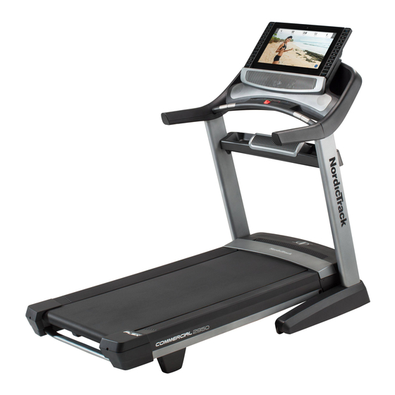
BEFORE YOU BEGIN Thank you for selecting the revolutionary reading this manual, please see the front cover of this NORDICTRACK COMMERCIAL 2950 treadmill. manual. To help us assist you, please note the product ® The COMMERCIAL 2950 treadmill offers an impres- model number and serial number before contacting us. -
Page 8: Part Identification Chart
PART IDENTIFICATION CHART Use the drawings below to identify small parts used for assembly. The number in parentheses below each draw- ing is the key number of the part, from the PART LIST near the end of this manual. The number following the key number is the quantity used for assembly. -
Page 9: Assembly
ASSEMBLY • Assembly requires two persons. • Left parts are marked “L” or “Left” and right parts are marked “R” or “Right.” • Place all parts in a cleared area and remove the packing materials. Do not dispose of the packing •... - Page 10 2. Make sure that the power cord is unplugged. Remove the tie securing the Upright Wire (83) to the front of the Base (93). Next, identify the Right Upright (84). Have a sec- ond person hold the Right Upright near the Base (93).
-
Page 11: 93). Make Sure Not To Pinch The Upright Wire
4. Hold the Right Upright (84) against the Base (93). Make sure not to pinch the Upright Wire (83). Attach the Right Upright (84) with two 3/8" x 2 3/4" Screws (23), two 3/8" x 1 1/4" Screws (20), and four 3/8" Star Washers (25) as shown; do not fully tighten the Screws yet. - Page 12 6. Carefully slide the Upright Crossbar (76) between the Right and Left Uprights (84, 91). Attach the Upright Crossbar with four 5/16" x 3/4" Screws (1); start all four Screws, and then tighten them. 7. Hold the Tray (79) near the Right Upright (84). Locate the tie (F) in the indicated hole (G) in the Right Upright.
- Page 13 8. Attach the two Handrails (74) to the Right and Left Uprights (84, 91) with two of the 5/16" x 2" Screws (2) that you removed in step 5 and two 5/16" Star Washers (8); do not fully tighten the Screws yet. Be careful not to pinch the Upright Wire (83) or the fan wire (H) on the right side.
- Page 14 10. IMPORTANT: To avoid damaging the Pulse Crossbar (80), do not use power tools, and do not overtighten the #10 x 3/4" Screws (6) or the 5/16" x 2" Screws (2). Orient the Pulse Crossbar (80) as shown. Attach the Pulse Crossbar with two of the 5/16" x 2" Screws (2) that you removed in step 5, two 5/16"...
- Page 15 12. Attach the console assembly (J) to the Handrails (74) with four 5/16" x 2" Screws (2) and four 5/16" Star Washers (8); start all four Screws, and then tighten them. Be careful not to pinch the wires (O). 13. Insert the wires (L, M) into the top of the Right Upright (84).
- Page 16 14. Start eight #8 x 3/4" Truss Head Screws (24) into the Pulse Crossbar (80), and then tighten them; do not overtighten the Truss Head Screws. 15. Set the Left Handrail Top Cover (73) on the left Handrail (74). Start four #8 x 3/4" Truss Head Screws (24) into the Left Handrail Bottom Cover (75), the left Handrail, and the Left Handrail Top Cover.
- Page 17 16. Raise the Frame (52) to the upright position. IMPORTANT: Do not raise the Frame past the vertical position. Have a second person hold the Frame until step 18 is completed. Remove the two 5/16" x 1 1/4" Screws (16) from the Latch Crossbar (121).
- Page 18 18. Remove the 5/16" Nut (9) and the 5/16" x 2 1/4" Bolt (4) from the bracket on the Frame (52). Align the upper end of the Storage Latch (56) with the bracket on the Frame (52), and insert a 5/16"...
-
Page 19: The Chest Heart Rate Monitor
THE CHEST HEART RATE MONITOR HOW TO PUT ON THE HEART RATE MONITOR • Store the heart rate monitor in a warm, dry place. Do not store the heart rate monitor in a plastic bag or If the heart rate monitor looks like the one shown other container that may trap moisture. -
Page 20: How To Use The Treadmill
HOW TO USE THE TREADMILL HOW TO CONNECT THE POWER CORD more amps. To avoid overloading the circuit, do not plug other electrical devices, except for low- Use a Surge Suppressor power devices such as cell phone chargers, into the surge suppressor or into an outlet on the same Your treadmill, like other electronic equipment, can be circuit. - Page 21 CONSOLE DIAGRAM FEATURES OF THE CONSOLE In addition, the console features a selection of onboard workouts. Each workout automatically controls the The advanced incline trainer console offers a selec- speed and incline of the incline trainer as it guides you tion of features designed to make your workouts more through an effective exercise session.
- Page 22 HOW TO TURN ON THE POWER HOW TO USE THE TOUCH SCREEN IMPORTANT: If the incline trainer has been The console features a tablet with a full-color touch exposed to cold temperatures, allow it to warm to screen. The following information will help you become room temperature before you turn on the power.
- Page 23 HOW TO SET UP THE CONSOLE 5. Check for firmware updates. Before using the incline trainer for the first time, set up First, touch the profile button in the lower-right the console. corner to select the settings main menu. Then, see step 2 on page 30 and select the maintenance 1.
- Page 24 HOW TO USE THE MANUAL MODE 4. Change the incline of the incline trainer as desired. 1. Insert the key into the console. To change the incline of the incline trainer, press See HOW TO TURN ON THE POWER on page the incline increase and decrease buttons or one of 22.
- Page 25 • The approximate number of calories you are To measure your heart rate, stand on the foot burning per hour rails and hold the contacts with your palms for approximately ten seconds; avoid moving your • Your heart rate (see step 6) hands.
- Page 26 HOW TO USE A MAP WORKOUT The workout will function in the same way as the manual mode (see pages 24 and 25). 1. Insert the key into the console. When you reach the end of the workout, the See HOW TO TURN ON THE POWER on walking belt will slow to a stop, and a workout page 22.
- Page 27 HOW TO USE A DRAW YOUR OWN MAP 5. Start the workout. WORKOUT Touch the Start button on the screen to start the 1. Insert the key into the console. workout. A moment after you touch the button, the walking belt will begin to move. Hold the handrails See HOW TO TURN ON THE POWER on and begin walking.
- Page 28 HOW TO USE A DISTANCE OR TIME WORKOUT 5. Select a distance or time workout that you have previously added to your schedule on iFit.com. Note: To use a distance or time workout, you must have access to a wireless network (see HOW TO USE Touch the calendar icon to download a distance or THE WIRELESS NETWORK MODE on page 31).
- Page 29 HOW TO USE THE WORKOUT SETTINGS SECTION HOW TO USE THE EQUIPMENT SETTINGS SECTION 1. Select the settings main menu. 1. Select the settings main menu. Insert the key into the console (see HOW TO TURN ON THE POWER on page 22). Next, See step 1 at the left.
- Page 30 HOW TO USE THE MAINTENANCE SECTION 4. Calibrate the incline system of the incline trainer. 1. Select the settings main menu. Touch the Calibrate Incline button. Then, touch the See step 1 on page 29. Begin button to calibrate the incline system. The incline trainer will automatically rise to the maxi- 2.
- Page 31 HOW TO USE THE WIRELESS NETWORK MODE An information box will ask if you want to connect to the wireless network. Touch the Connect button The console features a wireless network mode that to connect to the network or touch the Cancel but- allows you to set up a wireless network connection.
- Page 32 HOW TO USE THE SOUND SYSTEM HOW TO ADJUST THE ANGLE OF THE CONSOLE To play music or audio books through the console You can adjust the angle of the console by holding sound system while you exercise, plug a 3.5 mm male both sides of the console and tilting it to the desired to 3.5 mm male audio cable (not included) into the position.
-
Page 33: How To Fold And Move The Treadmill
HOW TO FOLD AND MOVE THE TREADMILL HOW TO FOLD THE TREADMILL HOW TO MOVE THE TREADMILL To avoid damaging the treadmill, adjust the incline Before moving the treadmill, fold it as described at the to zero before you fold the treadmill. Then, remove left. -
Page 34: Maintenance And Troubleshooting
MAINTENANCE AND TROUBLESHOOTING MAINTENANCE b. After the power cord has been plugged in, make sure that the key is inserted into the console. Regular maintenance is important for optimal perfor- mance and to reduce wear. Inspect and properly tighten c. Check the power switch located on the treadmill all parts each time the treadmill is used. - Page 35 SYMPTOM: The incline of the treadmill does not c. Your treadmill features a walking belt coated with change correctly high-performance lubricant. IMPORTANT: Never apply silicone spray or other substances to a. Calibrate the incline system of the treadmill (see the walking belt or the walking platform unless step 4 on page 30).
- Page 36 b. If the walking belt slips when walked on, fi rst SYMPTOM: The console does not stay in place remove the key and UNPLUG THE POWER CORD. Using the hex key, turn both idler roller a. If the console does not stay in the desired position screws clockwise 1/4 of a turn.
-
Page 37: Exercise Guidelines
EXERCISE GUIDELINES Burning Fat—To burn fat effectively, you must exer- WARNING: cise at a low intensity level for a sustained period of Before beginning this time. During the first few minutes of exercise, your or any exercise program, consult your physi- body uses carbohydrate calories for energy. -
Page 38: Part List
PART LIST Model No. NTL22116.0 R0117A Key No. Qty. Description Key No. Qty. Description 5/16" x 3/4" Screw Drive Roller/Pulley 5/16" x 2" Screw Frame 5/16" x 1 3/4" Bolt 5/16" x 2 1/4" Bolt Drive Motor #8 x 3/4" Screw Motor Belt #10 x 3/4"... - Page 39 Key No. Qty. Description Key No. Qty. Description Right Tray Cushion Rod Foot Rail Plate Cushion Wheel Right Rear Cap 1/4" x 3/4" Screw Key/Clip Controller Clamp Console Frame Cap Cushion Rod Bushing Console Frame Latch Crossbar Wire Tie Base Pad Speaker M10 Spring Washer Chest Heart Rate Monitor...
-
Page 40: Exploded Drawing
EXPLODED DRAWING A Model No. NTL22116.0 R0117A... - Page 41 EXPLODED DRAWING B Model No. NTL22116.0 R0117A 127 112...
- Page 42 EXPLODED DRAWING C Model No. NTL22116.0 R0117A...
- Page 43 EXPLODED DRAWING D Model No. NTL22116.0 R0117A...
-
Page 44: Ordering Replacement Parts
ORDERING REPLACEMENT PARTS To order replacement parts, please see the front cover of this manual. To help us assist you, be prepared to provide the following information when contacting us: • the model number and serial number of the product (see the front cover of this manual) •...
Need help?
Do you have a question about the NTL22116.0 and is the answer not in the manual?
Questions and answers