Table of Contents
Advertisement
Advertisement
Table of Contents

Related Manuals for Teac DV-H500


Summary of Contents for Teac DV-H500
-
Page 2: Table Of Contents
SECTION 1 SUMMARY CONTENTS PRODUCT SAFETY SERVICING GUIDELINES FOR VIDEO PRODUCTS ..........1-3 SERVICING PRECAUTIONS ........................1-4 * General Servicing Precautions * Insulation checking prodedure * Electrostatically Sensitive Devices SPECIFICATIONS ............................1-5 LOCATION OF CUSTOMER CONTROLS ..................1-6 ~ 1-7... -
Page 3: Product Safety Servicing Guidelines For Video Products
PRODUCT SAFETY SERVICING GUIDELINES FOR VIDEO PRODUCTS CAUTION : DO NOT ATTEMPT TO MODIFY THIS PRODUCT IN VOLTAGE MEASURE MUST NOT EXCEED 75 VOLTS R.M.S. ANY WAY. NEVER PERFORM CUSTOMIZED INSTALLATIONS THIS CORRESPONDS TO 0.5 MILLIAMP A.C ANY VALUE WITHOUT MANUFACTURER’S APPROVAL. UNAUTHORIZED EXCEEDING THIS LIMIT CONSTITUTES A POTENTIAL MODIFICATIONS WILL NOT ONLY VOID THE WARRANTY, BUT SHOCK HAZARD AND MUST BE CORRECTED IMMEDIATELY. -
Page 4: Servicing Precautions
SERVICING PRECAUTIONS CAUTION : Before servicing the DVD player covered by this service Electrostatically Sensitive (ES) Devices data and its supplements and addends, read and follow the SAFETY Some semiconductor (solid state) devices can be damaged easily by PRECAUTIONS. NOTE : if unforeseen circumstances create conflict static electricity. -
Page 5: Specifications
SPECIFICATIONS DVD VIDEO PLAYER Power supply .............. AC 230 V, 50 Hz (EUR)/ 120 V, 60 Hz (US/CANADA) Power consumption ............ 22 W External dimensions (W x H x D) ........ 285 x 131 x 292 mm Weight (net) ..............3.9 kg Signal system ............. -
Page 6: Location Of Customer Controls
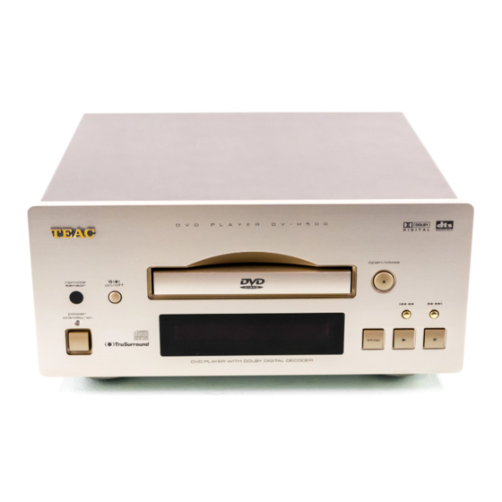
LOCATION OF CUSTOMER CONTROLS FRONT PANEL SKIP/SCAN OPEN/CLOSE Remote sensor TruSurround button buttons Disc Tray Display Window STOP button POWER/Standby button and indicator PLAY button (Standby mode : Red color) PAUSE button REAR PANEL S-VIDEO OUT jack [EUR only] AV CONNECTOR jack VIDEO OUT jack Audio 5.1CH OUT jacks Remote Control jacks... -
Page 7: Display Window
DISPLAY Window RANDOM indicator PROGRAM indicator CHAPTER indicator RESUME indicator TRACK indicator REPEAT indicator PLAY indicator TITLE indicator REMAIN indicator VIDEO CD indicator 5.1 CH & SRS indicator DVD indicator REMOTE CONTROL POWER button OPEN/CLOSE button REPEAT button A-B button SHUFFLE SET UP button (RANDOM) button... - Page 8 DISPLAY Window RANDOM indicator PROGRAM indicator CHAPTER indicator RESUME indicator TRACK indicator REPEAT indicator PLAY indicator TITLE indicator REMAIN indicator VIDEO CD indicator 5.1 CH & SRS indicator DVD indicator REMOTE CONTROL POWER button OPEN/CLOSE button REPEAT button A-B button SET UP button SHUFFLE (RANDOM) button...
-
Page 9: Electrical Troubleshooting Guide
ELECTRICAL TROUBLESHOOTING GUIDE 1. SYSTEM CHECK Power ON. Standby LED ON? Refer to Front Part. Does Bar appear at FLD? Is CN04 Reconnect Connected normally? Replace Main B/D Do all eight Bars appear? Check Power. Is CN06, CN07 "CHECK" message Connected normally? appear? Is CN04 Pin... -
Page 10: Power Circuit
2. Power Circuit Input Voltage : 230 V It is possible to malfunction, if the unload condition is left for a long time when power on. (More than Dummy load 100mA) The resistor value of both terminal is measured with DVM crossing each other to check the each element is normal or abnormal. (It is normal when the numerical value is different each other.) START Is F601 normal? -
Page 11: Mpeg Circuit
3. MPEG Circuit Power ON Does DVD Does OSD LOGO appear Check VIDEO part appear normally? on the screen? Check IC23 Does the moving picture of the Check IC22 and IC23 DVD Disc play on the screen normally? Does OSD appear Check IC22 normally? Does the... - Page 12 4. FRONT Circuit (Digtron & Key) STRAT Power ON. Is oscillation of LED ON? Check Power. X901 normal? Check waveform Is Display on normally? Replace Q902. of IC91 Pin 32 . Check the pattern between IC91 and FIP1. Do all the Check waveform Is waveform of IC91 buttons work...
- Page 13 5. ETC A. Audio abnormal D. Video abnormal VIDEO ABNORMAL AUDIO ABNORMAL Check Audio Jack. Check Video Jack. Check the Mute TR. Refer to Video part. Refer to MPEG part. Refer to Audio part. Replace B/D. Refer to MPEG part. Replace B/D.
- Page 14 IC BLOCK DIAGRAMS & PIN DESCRIPTION 1. IC25 (STi5505 DVD BACKEND-DECODER) PIN DESCRIPTION Name Type Function SUPPLIES 1, 18, 34, 67, 75, 86, 95, Power Supply (3.3 V) 102, 110, 119, 130, 139, 149, 159, 171, 184, 208 4, 19, 35, 68, 77, 87, 96, Ground 103, 111, 120, 131, 140, 150, 160, 172, 185, 200...
- Page 15 IC BLOCK DIAGRAMS & PIN DESCRIPTION 1. IC25 (STi5505 DVD BACKEND-DECODER) PIN DESCRIPTION Name Type Function SUPPLIES 1, 18, 34, 67, 75, 86, 95, Power Supply (3.3 V) 102, 110, 119, 130, 139, 149, 159, 171, 184, 208 4, 19, 35, 68, 77, 87, 96, Ground 103, 111, 120, 131, 140, 150, 160, 172, 185, 200...
- Page 16 Name Type Function EXTERNAL MEMORY INTERFACE 161-170, 173-183 ADR[1:21] External Memory Address Bus 141-148, 151-158 DATA[0:15] External Memory Data Bus DRAM RAS or reserved RAS1/HOLDREQ WAIT/READY External Wait States or Reserved DRAM R/W Strobe or Reserved R/W/DMAACK 121, 122 Byte enable BE[0:1] DRAM CAS or Reserved CAS0/HOLDACK...
- Page 17 PIN CONNECTIONS DATA[13] PIO3[7] DATA[12] PIO2[0] DATA[11] DATA[10] PIO2[3] DATA[9] PIO2[4] DATA[8] PIO2[5] PIO2[7] PIO1[0] DATA[7] PIO1[2] DATA[6] DATA[5] PIO1[5] PIO1[6] DATA[4] PIO1[7] DATA[3] PIO4[7] DATA[2] PIO0[0] DATA[1] PIO0[3] DATA[0] PIO0[4] PPC_MODE PIO0[5] PROCCLK STi5505 PIO0[6]/PCM_OUT2 WAIT/READY PIO0[7] IRQ[0] DMAXFER PCM_OUT1 R/W/DMAACK IRQ[1]...
- Page 18 2. IC19 (PCM1600 6CH DAC) PIN DESCRIPTION P I N N A M E I / O DESCRIPTION ZERO1 Zero Data Flag for V ZERO2 Zero Data Flag for V ZERO3 Zero Data Flag for V ZERO4 Zero Data Flag for V ZERO5 Zero Data Flag for V ZERO6...
- Page 19 BLOCK DIAGRAM Output Amp and Low-Pass Filter LRCK Output Amp and Audio Low-Pass Filter Serial DATA1 DATA2 Output Amp and Enhanced Oversampling DATA3 Low-Pass Filter Multi-level Digital Filter Delta-Sigma with Modulator Function Output Amp and Controller Low-Pass Filter TEST Serial Output Amp and Control Low-Pass Filter...
- Page 20 3. IC26 (MBM29F800BA FLASH ROM) PIN DESCRIPTION LOGIC SYMBOL BLOCK DIAGRAM 2-20...
- Page 21 PIN CONNECTIONS TSOP(I) (Marking Side) BYTE N.C. N.C. MBM29F800TA/MBM29F800BA RESET Standard Pinout N.C. N.C. RY/BY FPT-48P-M19 2-21...
- Page 22 4. IC22, IC23 (KM416S1120D 16M SDRAM) PIN DESCRIPTION Name Input Function System Clock Active on the positive going edge to sample all inputs. Disables or enables device operation by masking or enabling all inputs except Chip Select CLK, CKE and L(U)DQM Masks system clock to freeze operation from the next clock cycle.
- Page 23 BLOCK DIAGRAM Data Input Register LDQM Bank Select 512K x 16 512K x 16 Column Decoder Latency & Burst Length LCKE Programming Register LRAS LCBR LCAS LWCBR LDQM Timing Register L(U)DQM Samsung Electronics reserves the right to change products or specification without notice.
- Page 26 5. IC91 (CXP50112 FRONT u-COM) PIN DESCRIPTION PIN NO. DESCRIPTION REMARK PIN NO. DESCRIPTION REMARK NO CONNECTION FROM MAIN PCB KBDOUTCLK NO CONNECTION FROM MAIN PCB KBDOUT POWERON TO MAIN PCB SOUNDMUTE NO CONNECTION RETURN0 RETURN1 KEY SCAN RETURN RETURN2 RETURN3 SYSID_O SYSTEM REMOCON...
- Page 27 PIN CONNECTIONS SCAN1 SCAN0 NOT USED NOT USED NOT USED NOT USED SYSIN_I SYSIN_O RETURN3 RETURN2 RETURN1 RETURN0 SOUNDMUTE POWERON KBDOUT KBDOUTCLK 2-27...
-
Page 54: Exploded View
KTS3+6J INCLUDED ACCESSORIES REF. NO. PARTS NO. DESCRIPTION REMARKS 9A07928800 OWNER'S MNL J, DV-H500 [J] KQX1A601Z 9A07928600 OWNER'S MNL E/F DV-H500 [US, C] KQX1A588Z 9A07928700 OWNER'S MNL E/F/I/G/S DV-H500 [E] KQX1A590Z 9A08143200 REMOCON XMTR AS KRC-4515B BARTDVH500 9A08143300 CORD,PHONE KJS4M011Z... -
Page 55: Electrical Parts List
SECTION 3 ELECTRICAL PARTS LIST RESISTORS AND CAPACITORS Notes : • Part numbers are indicated for most mechanical parts. Please use this part number for parts order. • The unit of resistance is OHM K=1000 (OHM ), M=1000 (K • The unit of capacitance is MICROFARAD (µF) P=10 µF Numbering System of Resistor... - Page 56 MAIN PCB ASS'Y REF. NO. PARTS NO. DESCRIPTION REMARKS 9A08144600 MAIN PCB ASS'Y [J, US, C] KOP11307D 9A08144620 MAIN PCB ASS'Y KOP11307B IC02 9A05218300 IC , KA7808-ABTU KVIKA7808A IC04 9A05218300 IC , KA7808-ABTU KVIKA7808A CN05 9A05328900 WAFER MOLEX 5267-02A KJP02GA01ZM CN04 9A05330300 WAFER MOLEX53014-0810 KJP08GA19ZM...
- Page 57 SUB PCB ASS'Y REF. NO. PARTS NO. DESCRIPTION REMARKS 9A08143900 SUB PCB ASS'Y KOP11324B X901 9A05192900 CRYSTAL , DC-D1800 KOX04194E120C CN99 9A05329700 WAFER MOLEX53014-0610 KJP06GA19ZM JK91 9A06230200 JACK , REMOTE(2P) KJJ4N023Z RZ91- 94 9A06244000 RES , NETWORK KRGSN7X104J SW91 9A06675300 SWITCH SLIDE KSS2B016Z RC91 9A06757900 SENSOR , REMOCON...
- Page 58 TEAC NEDERLAND BV Oeverkruid 15, NL-4941 VV Raamsdonksveer, Nederland Phone: 0162-510210 TEAC BELGIUM NV/SA c/o TEAC NEDERLAND BV, Oeverkruid 15, NL-4941 VV Raamsdonksveer, Nederland Phone: 0162-510860 TEAC ITALIANA S.p.A. Via C. Cantù 11, 20092 Cinisello Balsamo, Milano, Italy Phone: 02-66010500 TEAC AUSTRALIA PTY., LTD.
Need help?
Do you have a question about the DV-H500 and is the answer not in the manual?
Questions and answers