Arjohuntleigh Maxi Sky 440 Technical Manual
Hide thumbs
Also See for Maxi Sky 440:
- Instructions for use manual (34 pages) ,
- Instructions for use manual (32 pages)
Table of Contents
Advertisement
Advertisement
Table of Contents

Related Manuals for Arjohuntleigh Maxi Sky 440


Summary of Contents for Arjohuntleigh Maxi Sky 440
- Page 1 Maxi Sky 440 Technical Manual 001.16010.33 rev. 8 • July 2013...
- Page 2 ® and ™ are trademarks belonging to the ArjoHuntleigh group of companies. © ArjoHuntleigh 2011. As our policy is one of continuous improvement, we reserve the right to modify designs without prior notice.The content of this publication may not be copied either whole or in part without the consent of ArjoHuntleigh.
-
Page 3: Table Of Contents
How do I enter into service mode? : ......................... 24 How do I adjust the current limiter mode? : ...................... 24 How to read the number of cycles made by the Maxi Sky 440: ................ 25 How to reset service light: ..........................25 ... - Page 4 Table of Contents User Inspections ..............................27 Inspections by an Authorized Service Technician .....................28 Daily Checklist ..............................29 Inspection and Cleaning ............................29 Handling and Storage ............................30 Verification of the Charger’s Power Source ......................31 Sling Inspection and Care ..........................31 ...
-
Page 5: Safety Instructions
Safe Working Load plate underneath the housing of the lift. The Maxi Sky 440 has been designed with a lifting capacity of 200 kg (440 lb). • Replace any precautionary or instruction... -
Page 6: Updating Instructions
Updating Instructions VERIFY THAT THE LATEST UPDATES HAVE BEEN IMPLEMENTED Verify on Careprosis if there were any field correction bulletins, safety notices or technical bulletins that have been published since the last service. http://www.careprosis.com This verification must be done to keep the product up to date according to safety and product improvements. -
Page 7: Product Description
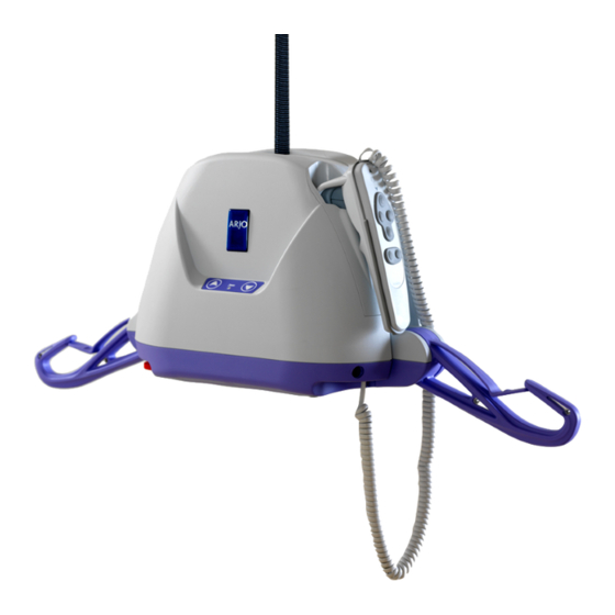
Product Description Hand Control Carabiner Pass through Hook Emergency Lowering Key Pocket for storage of hand control Emergency Stop Button Front Panel with UP/DOWN DC Inlet for Button charger Power cord 1.5 m Universal Charger with Adaptors Charger... -
Page 8: Service Procedures
Service Procedures Hand Control Replacement Required tools: • None 1. To replace the defective hand control, disconnect the hand control plug from under the lift. 2. Plug the new one making sure that the connector latches in place. Pull gently to confirm that the connector is secure. Bottom Plastic Cover Replacement Required tools: •... -
Page 9: Main Plastic Cover Replacement
Service Procedures 12. Reinstall the switch to the button housing and turn the locking clip clockwise to secure it in place. Gently pull the switch up to make sure that the clip (or clip spring) is retaining the assembly. 13. Put the lift upside down to place the bottom cover back with the eight screws. -
Page 10: Batteries Replacement
Service Procedures 7. Install the new plastic cover. 8. Connect the touch pad membrane to the main circuit board. Refer to “Touch Pad Membrane Replacement” on page 15 for specific note concerning membrane connection. 9. Reinstall the hand control connector PCB. 10. -
Page 11: Fuse Replacement
Service Procedures Fuse Replacement Required tools: • None 1. Refer to “Batteries Replacement” above to access the fuse holder. 2. Pull out the fuse holder and open it (unscrew both parts) to access the fuse. 3. Remove the fuse and replace it with a new one (PN C8FGMA10). -
Page 12: Folding Arm Replacement
Service Procedures Folding Arm Replacement Required tools: • Small flat head screwdriver • Long nose pliers • Plastic hammer • Punch 1. Refer to "Main Plastic Cover Replacement” on page 9 to remove the plastic covers. 2. Locate the folding supports and remove both retaining clips using a small flat head screwdriver. -
Page 13: Hand Control And Charger Interface Circuit
Service Procedures Hand Control and Charger Interface Circuit Required tools: • Screwdriver Torx T20 1. Refer to “Bottom Plastic Cover Replacement” on page 8 to remove the bottom cover and access the interface circuit. 2. Remove the hand control and charger interface circuit board using a Torx T-20 screwdriver. -
Page 14: Wiring Harness Replacement
Service Procedures Wiring Harness Replacement Required tools: • 8-mm socket 1. Refer to “Main Circuit Board Replacement” on page 13 to remove the main circuit board. 2. Unplug wiring from the limit switch. 3. Replace wiring harness with a new one. 4. -
Page 15: Touch Pad Membrane Replacement
Service Procedures Touch Pad Membrane Replacement Required tools: • None 1. Refer to "Main Plastic Cover Replacement” on page 9 to access the touch pad membrane. 2. Remove the membrane located in front of the main cover. 3. Carefully insert the flat cable connector of the membrane into the hole then apply the membrane sticker to the cover. -
Page 16: Battery Charger Replacement
Service Procedures Battery Charger Replacement Required tools: • None Battery Charger 700.13510.33 (OBSOLETE) Battery Charger 700-24201 (OBSOLETE) This charger has been replaced by the wall This charger has been replaced by the wall mounted charger 700-15567 which requires to mounted charger 700-15567 which requires to have the touch pad membrane 001-08100-33 have the touch pad membrane 001-08100-33 (featuring a charge indicator light) on the unit. -
Page 17: Limit Switch Rod Replacement
Service Procedures Limit Switch Rod Replacement Required tools: • Cutter pliers • Long nose pliers • Pop-rivet installation tool 1. Refer to "Main Plastic Cover Replacement” on page 9 to remove plastic covers. 2. Remove the spring from the upper limit shaft. 3. -
Page 18: Strap Replacement
Service Procedures Strap Replacement Required tools: • 4 mm- Allen Key 1. Refer to "Main Plastic Cover Replacement” on page 9 to remove plastic covers. 2. Refer to “Strap Inlet Replacement” on page 11 to remove the strap inlet. 3. Refer to “Main Circuit Board Replacement” on page 13 to remove the main circuit board. -
Page 19: Drum Replacement
Service Procedures Drum Replacement Required tools: • Retaining ring pliers 1. Refer to "Main Plastic Cover Replacement” on page 9 to remove plastic covers. 2. Refer to “Pass Through Hook Replacement” on page 11 to remove the Pass Though Hook 3. -
Page 20: Strap Roll Replacement
Service Procedures Strap Roll Replacement Required tools: • Retaining ring plier 1. Refer to "Main Plastic Cover Replacement” on page 9 to remove plastic covers. 2. Refer to “Pass Through Hook Replacement” on page 11 to remove the Pass Though Hook. 3. -
Page 21: Motor And Transmission Replacement
Service Procedures Motor and Transmission Replacement Required tools: • 12 mm socket hex tool • Ratchet 1. Refer to "Main Plastic Cover Replacement” on page 9 to remove plastic covers. 2. Refer to "Main Circuit Board Replacement” on page 13 to access and remove the circuit board. 3. -
Page 22: Cblm Plate Replacement
Service Procedures 13. Couple the CBLM block plate into the slot at the end of the worm. 14. Reinstall the three screws that maintains the motor. 15. Test the CBLM plate attached with the worm. Move the plate left and right, the plate must easily move with the worm. - Page 23 Service Procedures 8. Reinstall the strap inlet (see “Strap Inlet Replacement" on page 18 for detail). 9. Reinstall the Pass Through Hook (see “Pass Through Hook Replacement” on page 11 for details). 10. Reinstall the plastic covers. (see “Bottom Plastic Cover Replacement” on page 8 and “Main Plastic Cover Replacement”...
-
Page 24: Programming
Programming Service Mode The Maxi Sky 440 service hand control (# 700.13620.33 or 700-13840 – not included) is required to access the service mode (service light setting). Note: In order to prevent the user from accidentally entering into service mode while using the lift, the three buttons hand control is not included. -
Page 25: How To Read The Number Of Cycles Made By The Maxi Sky 440
Programming How to read the number of cycles made by the Maxi Sky 440: 1. Select parameter 4 in the service mode (4 beeps). 2. After you have heard the 4 beeps, push on the X button on the hand control to select the option. -
Page 26: Conversion Table
Programming Conversion table Number of Number of beeps cycles 1029 1286 1543 1800 2057 2314 2571 2829 3086 3343 3600 3857 Lift service light is 4114 turned on 4371 4629 Lift service light or/and 4886 warning beeps audible 5143 5400 5657 5914 6171... -
Page 27: Care And Maintenance
WARNING: Safety related maintenance and authorized service must be carried out by qualified personnel, fully trained in servicing procedures by ArjoHuntleigh, and equipped with correct tools. Failure to meet these requirements could result in personal injuries and/or unsafe equipment. -
Page 28: Inspections By An Authorized Service Technician
NOTE: If the product does not work as intended, immediately contact your local ArjoHuntleigh representative for support. -
Page 29: Daily Checklist
WARNING: Before each use, make sure all rail end stoppers are in place and secured. Inspection and Cleaning To clean the Maxi Sky 440, wipe it down with a damp cloth using warm water and a disinfectant cleaner. Disinfectant wipes, supplied already impregnated with a 70% v/v solution of isopropyl alcohol, can also be used. -
Page 30: Handling And Storage
NOTE: Even if the lift is not used, ArjoHuntleigh recommends charging the batteries at least every two weeks. This will prevent premature aging of batteries. If you store or ship the Maxi Sky 440, ensure that the power is turned off (emergency button pushed in) beforehand. -
Page 31: Verification Of The Charger's Power Source
Verification of the Charger’s Power Source If the light does not illuminate when there are batteries correctly installed in the Maxi Sky 440, try the following: 1. Make sure that the charger is correctly plugged into the AC outlet and verify the status of the charge indicator light according to charger model. -
Page 32: Troubleshooting
Troubleshooting Problem To check The red “service” light is on and Contact your local ArjoHuntleigh representative for flashing. maintenance. The unit starts and stops repetitively. If the load is greater than the unit’s safe working load, it will not function due to an overload protection on the motor. -
Page 33: Labels On The Lift
Labels on the Lift 1. Product Name 2. Serial Number Label 3. Charger Information... -
Page 34: Wiring Diagram
Wiring Diagram... -
Page 35: Technical Specifications
Battery capacity Provides up to 30 transfers with a load of 80 kg (176 lb) 700-13860: IPX4 Degree of protection – Hand control 700-13865: IPX7 Degree of protection - Maxi Sky 440 IP21 Lift - protection class - shock prevention Internally powered equipment Battery Charger input 100-240 VAC, 50-60 Hz 700.13510.33: 27-29 VDC, 1A... - Page 36 WARNING: Radio transmitting devices such as mobile telephones, two-way radios, etc., should never be used near the Maxi Sky 440 since they can interfere with the function of the lift. Cables from potentially strong sources of electromagnetic fields should not be placed near the unit.
-
Page 37: Dimensions
Technical Specifications Dimensions... - Page 38 GETINGE GROUP is a leading global provider of products and systems that contribute to quality enhancement and cost efficiency within healthcare and life sciences. We operate under the three brands of ArjoHuntleigh, GETINGE and MAQUET. ArjoHuntleigh focuses on patient mobility and wound management solutions.
Need help?
Do you have a question about the Maxi Sky 440 and is the answer not in the manual?
Questions and answers
I have a Maxi Sky 440. I need to take the batteries out for long term storage. How do I best open it.