
Subscribe to Our Youtube Channel
Related Manuals for ISCO Signature


Summary of Contents for ISCO Signature
- Page 1 Installation and Operation Guide Manual #69-4333-004 of Assembly #60-4334-005 Copyright © 2012. All rights reserved, Teledyne Isco Revision J, October 2017...
- Page 3 Teledyne Isco recommends that you read this manual completely before placing the equipment in service. Although Teledyne Isco designs reliability into all equipment, there is always the possibility of a malfunction. This manual may help in diagnosing and repairing the malfunction.
-
Page 5: Table Of Contents
1.5 Identifying Signature Components ........ - Page 6 2.8.4 Sensor Diagnostics ..........2-31 2.8.5 Display Signature Information ........2-31 2.8.6 Display License Information .
- Page 7 6.6.1 Signature Flow Meter ........
- Page 8 B.2 Signature Flow Meter Accessories........
- Page 9 3-13 Location of power supply ......... . . 3-12 3-14 Signature Flow Meter mounted on wall ....... 3-12...
- Page 10 4-3 One of the eight screws loosened........4-2 4-4 Signature tilted up in preparation of removal ......4-3 4-5 Signature in upward facing position .
- Page 11 4-3 Default Method for Portable Signature ....... . . 4-8...
- Page 12 Signature® Flow Meter Table of Contents...
- Page 13 Signature® Flow Meter Safety Signature® Flow Meter Safety General Warnings Before installing, operating, or maintaining this equipment, it is imperative that all hazards and preventive measures are fully understood. While specific hazards may vary according to location and application, take heed of the following general...
- Page 14 Signature® Flow Meter Safety The equipment and this manual use symbols used to warn of Hazard Symbols hazards. The symbols are explained below. Hazard Symbols Warnings and Cautions The exclamation point within the triangle is a warning sign alerting you of important instructions in the instrument’s technical reference manual.
- Page 15 Signature® Flow Meter Section 1 Introduction The Signature Flow Meter is designed for open channel flow monitoring applications using any combination of flow and parameter measurement technologies and sampling, depending on what is required at the monitoring site. The bubble line is anchored in the flow stream at the appropriate measuring point in the weir, flume, or other open channel flow situation.
-
Page 16: Quick Start
Signature® Flow Meter Section 1 Introduction 1.1 Quick Start Enter: . . . Numerical: • Enter values • Type characters • Open list • Confirm selection • Activate field Arrows: . . . • = Pull down list available • Navigate up, down, left, right • = Character grid available Soft Keys: Delete / Exit: •Clear last entry • Exit list • Close window • Current displayed function Decimal: • = Return to last menu Back • Navigate up one screen at a time • = Confirm & advance to next ... -
Page 17: Data Integrity
Signature® Flow Meter Section 1 Introduction 1.2 Data Integrity What makes the Signature Flow Meter unique is its ability to verify data integrity. This is accomplished by logging four special event data types that cannot be altered, and are designed to alert the user to any trends or anomalies, and to assess compliance. - Page 18 Signature® Flow Meter Section 1 Introduction When connected remotely via modem, the web interface of the Signature Flow Meter provides remote control and data access. Figure 1-2 Multiple options can be used in any combination...
-
Page 19: Identifying Signature Components
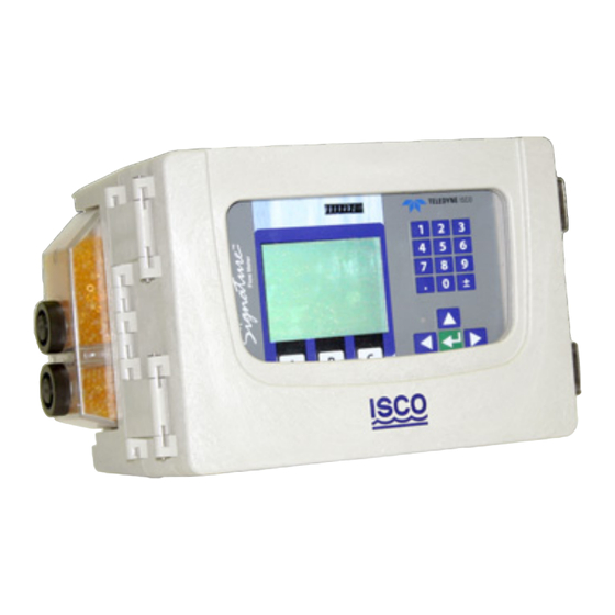
Signature® Flow Meter Section 1 Introduction 1.5 Identifying Signature The following are key components of the Signature Flow Meter: Components Injection molded UV protected sturdy enclosure USB Cable Connector Desiccant Holder (Used with TIENet 330 Bubbler, TIENet 350 AV Sensors, and 360... -
Page 20: Controls And Indicators
Signature® Flow Meter Section 1 Introduction 1.6 Controls and Before programming and operating the Signature Flow Meter, become familiar with the keypad and standard screens. Indicators 1.6.1 Keypad Keys are identified in Figure 1-4; keypad functions are detailed in Section 2.1.1. -
Page 21: Display And Led
Flow Meter, No Bubbler Signature w/o options: 4.5 kg (10 lbs) Signature w/ all interior options: 4.9 kg (10.7 lbs) Signature w/ all int. options + mounted battery backup: 7.8 kg (17.3 lbs) Bubbler Flow Meter Signature w/o options: 5.9 kg (13 lbs) Signature w/ all interior options: 6.1 kg (13.5 lbs) - Page 22 Isolation Galvanic Isolation Outputs per card Optional 307 TIENet Analog Input: Configurable either active (signature supplying loop power) or passive (rely- ing on loop power, signature is not powering the loop). Output voltage (in active mode) 17 VDC minimum Range...
-
Page 23: Tienet 330 Bubbler Module Technical Specifications
Signature® Flow Meter Section 1 Introduction Table 1-1 Signature Flow Meter Technical Specifications (Continued) Optional 308 TIENet Analog Output: Range 4 to 20 mA Isolation Monolithic Isolation Maximum Load 900 Outputs per card Industry Standard Inputs Two SDI-12, RS485 Modbus ASCII & RTU, 4-20 mA Analog Industry Standard Outputs 4-20 mA Analog, Modbus ASCII &... - Page 24 Signature® Flow Meter Section 1 Introduction Figure 1-5 Specification drawing: Signature Flow Meter with stand in side facing position 1-10...
-
Page 25: Specification Drawing: Signature Flow Meter With Stand In Upward Facing Position
Signature® Flow Meter Section 1 Introduction Figure 1-6 Specification drawing: Signature Flow Meter with stand in upward facing position 1-11... -
Page 26: Specification Drawing: Signature Bubbler Flow Meter, 1 Of 2
Signature® Flow Meter Section 1 Introduction Figure 1-7 Specification drawing: Signature Bubbler Flow Meter, 1 of 2 1-12... -
Page 27: Specification Drawing: Signature Bubbler Flow Meter, 2 Of 2
Signature® Flow Meter Section 1 Introduction Figure 1-8 Specification drawing: Signature Bubbler Flow Meter, 2 of 2 1-13... - Page 28 Signature® Flow Meter Section 1 Introduction 1-14...
-
Page 29: Section 2 Setup And Programming
Signature® Flow Meter Section 2 Setup and Programming The Signature Flow Meter is shipped from the factory with a default program already configured. The Signature Portable is shipped with different defaults than the Signature. Your par- ticular installation will normally require different program set- tings, specific to your monitoring site and application. -
Page 30: Connecting To The Signature With Flowlink
USB Driver for Signature In order for your computer to connect to the Signature flow meter through the micro-USB assembly, you must have the correct driver installed. USB drivers for both 32-bit and 64-bit operating systems are included with your flowlink program. -
Page 31: Flowlink Connect Screen
From the COM Port pull down list, select the port associated with the Signature. TCP connection is made from the computer to the Signature flow meter’s optional CDMA, GSM, or Ethernet modem. Enter the correct static IP and port number, separated by a colon, the correct public domain address. -
Page 32: Site Info Tab
Signature® Flow Meter Section 2 Setup and Programming Site Screen The Signature site screen has three tabs: Site Info contains information specific to this site. Enter all rel- evant information into the Site Info fields, including the desired Site Name, and save the information by clicking Apply. -
Page 33: Devices Tab
Signature® Flow Meter Section 2 Setup and Programming Devices lists the name, software version, and hardware version of the flow meter for offline viewing of the site file. This information, along with that of any connected TIENet devices, can be viewed from the specific flow meter’s firmware (refer to Sensor Diagnostics, on page 2-31). -
Page 34: Program Tab: Accessing The Browser
Signature® Flow Meter Section 2 Setup and Programming Program is the portal through which you access the Signature browser. The programming functions and displayed data in the browser are functions of the flow meter firmware, not Flowlink. The Browser Window... -
Page 35: The Home Screen
Shortcuts menu. The selections available in the Shortcuts menu are determined by what connected devices have been detected by the Signature flow meter. To access your shortcuts, press SHORTCUTS ( 2.3.1 Adjust Level To set a new level, enter the value in the field next to Level, and select Adjust. -
Page 36: Real-Time Measurement
Signature flow meter. 2.4.1 Off-Screen Content An arrow in the lower right corner of the flow meter’s screen (see symbols at left) indicates that there is additional content on this screen in the direction the arrow is pointing. -
Page 37: Pull Down Menus
Signature® Flow Meter Section 2 Setup and Programming I s c o Te s t S i t e Done Cancel B C D E F G H I J K L M N c d e f g h i j k l m n o p ) - _ + = <... -
Page 38: Program Steps
Sections 2.6 Hardware Setup, 2.7 Configure Options, 2.8 Administration, and 2.9 USB Options. This information can also be viewed by pressing the Help softkey on your Signature flow meter or its browser screen. Menu 1. Hardware Setup 2. -
Page 39: Hardware Setup
S m a r t S e n s o r S e t u p, b y S e r i a l refer to: Number and Device Type. Table C-1 Modbus Output Registers for Signature Flow Meter, on page C-4. SDI-12 Setup • Scan for Connected Sondes • Add/Remove •... -
Page 40: Smart Sensor Setup (Tienet)
2.6.1 Smart Sensor Setup This selection will display the most recently detected TIENet (TIENet) devices connected to the Signature flow meter. Perform Scan If TIENet devices have been added or removed from the system, highlight Perform Scan and press Enter to detect the current system configuration. -
Page 41: Measurement Parameters For Each Tienet Device
Signature® Flow Meter Section 2 Setup and Programming 300 Case Board: Sense Voltage Input Voltage Charge Voltage Charge Current Case Humidity Reference Humidity AC Power Rainfall Case Temperature 301 pH / Temperature Device: Temperature 304 Contact Output: 304 Digital Output... -
Page 42: Setup
Scan to detect the current system configuration. Following the scan, add/remove sondes from the Active list by selecting the sonde and clicking Add or Remove. To begin using an Isco-Ready sonde with its configured parameters, select Configure. 2.6.3 Modbus Input Setup... -
Page 43: Modbus Setup Worksheet
Units a. For 2100 update interval in seconds must be written to register 26. b. For assistance in calculating a multiplier and offset, contact Teledyne Isco. Big Endian = Most significant register first; Little Endian = Least significant register first. -
Page 44: Modbus Input Setup
Signature® Flow Meter Section 2 Setup and Programming Hardware Setup 1. Smart Sensor Setup (TIENet) 2. SDI-12 Setup 3. MODBUS Input Setup 4. MODBUS Output Setup 5. Modem Setup MODBUS Input Setup 1. MODBUS Input COM Settings 2. MODBUS Input Device Settings... -
Page 45: Editing Modbus Device Parameters
Signature® Flow Meter Section 2 Setup and Programming Select Little if a multiple register parameter has the low-order data in the first register; select Big if high-order. Select data size. The available Units of Measure are determined by the data type you select. -
Page 46: Modbus Output Setup
Connection to the flow meter is made via the RS-485 terminal on the Signature case board (shown in Figure 2-12 below). In the Device ID field, enter the Signature’s address (from 2 to 247) and configure the communication protocol. CAUTION Be careful not to assign the same address to more than one flow meter. -
Page 47: Configure Options
Signature® Flow Meter Section 2 Setup and Programming 2.7 Configure Options The Configure Options menu is used for setting up the mea- surement site and setting the program parameters. Configure Options 1. Site Setup 5. Data Storage/Push Setup 2. Measurement Setup 6. - Page 48 Setup), flow conversion (Flow Input Setup), and flow volume totalizer(s) (Volume Input Setup). Menu items that appear are dependent on what equipment is connected to the Signature flow meter. Level Input Setup – Under Level Setup, select the level input.
- Page 49 3. Select the flow conversion type to be used (Weir, Flume, Metering Inserts, Manning Formula, Area Velocity, Equa- tion, or Data Points); then set up the conversion. Note Additional information about flow conversions can be found in the Isco Flow Measurement Handbook included with the Sig- nature Flow Meter. 2-21...
-
Page 50: Menu Tree: Flow Rate Input Setup
Signature® Flow Meter Section 2 Setup and Programming Configure Options 2. Measurement Setup (example name) Flow Rate Input Setup 1. Flow Rate-A 2. Flow Rate-B 3. Flow Rate-C 4. Add Flow Rate Flow Rate-A 1. Measurement Settings 2. Flow Conversion For level-to-flow conversions only. -
Page 51: Measurement Setup
Signature® Flow Meter Section 2 Setup and Programming From the Resolution pull down menu, select the degree of reso- lution required for your total flow (lower = fewer digits to right of decimal; higher = more digits to right of decimal). -
Page 52: Adjust
Signature® Flow Meter Section 2 Setup and Programming Load Calculation Setup – This option allows you to setup the ..Figure 2-17 Menu for Load Calculation Setup 2.7.3 Adjust Adjust levels and/or velocity measurement, and/or calibrate mea- surement values for other connected TIENet devices. Level adjustment instructions can be found in Section Setting the Level, on page 3-18. - Page 53 Signature® Flow Meter Section 2 Setup and Programming Range – TRUE when a measured parameter value is inside or outside specified upper and lower limits. Rate of Change – TRUE when a measured parameter changes by a specified amount over a specified time duration.
-
Page 54: Data Storage/Push Setup
The display can be turned O and O in the configure options, site setup, and power options menu. Turning the display O effects the way the data is recorded by the Signature meter. 2-26... -
Page 55: Sampler Setup
(refer to Section 2.7.4 Equation/Trigger Setup). Alarms: Local Local alarms are viewed on the Signature Flow Meter itself. When a programmed alarm condition becomes true, the LED on the front panel glows red. -
Page 56: Local Alarm Setup
Signature® Flow Meter Section 2 Setup and Programming Note Server alarms notify a specified list of contacts in the event that a server running Flowlink Pro fails to receive pushed data from a site within a specified duration. For SMS and Server alarm setup, refer to Figure 2-20. -
Page 57: Sms And Server Alarm Setup (Modem Required)
Signature® Flow Meter Section 2 Setup and Programming Configure Options 1. Site Setup 5. Data Storage/Push Setup 2. Measurement Setup 6. Sampler Setup 3. Adjust 7. Inputs/Outputs/Alarms Setup 4. Equation/Trigger Setup 8. Reset Totalizers 9. Reports/History Setup Inputs/Outputs/Alarms Setup 1. Alarms 2. -
Page 58: Reset Totalizers
Administrative settings (see following page) dictate operating preferences and perform general housekeeping tasks. Administration Options 1. Language Options 5. Display Signature Information 2. Set New Passcode 6. Display License Information 3. Update Firmware 7. Gather Fault Data / USB Options 4. -
Page 59: Language Options
Signature® Flow Meter Section 2 Setup and Programming 2.8.1 Language Options Select Device Language – From the list, select the default lan- guage to be displayed by the Signature flow meter. Available lan- guages include: English (USA) Dansk Português (Brasil) Deutsch... -
Page 60: Gather Fault Data
This data can be displayed to assist in troubleshooting. To download the data to a flash drive, connect a flash drive to the micro-USB assembly on the front panel of the Signature and select Gather Fault Data from the USB Options menu that appears (refer to Section 2.9 USB Options). -
Page 61: Retrieve Text Reports
There is a check box that, when checked, will export the .cvs file onto a USB flash drive. 2.9.3 Update Firmware With a USB flash drive connected to the Signature’s front panel, the Update Firmware option becomes active on both the Admin- istration menu and the USP Options menu. -
Page 62: Save Current Program
Note that selecting this option will cause the current program to be overwritten with the one from the flash drive. In order for the Signature to load the correct program, the name of the site must match that of the site program that was saved. -
Page 63: Verifying Exported Reports
SITENAME \ MODULENAME \ DATE. 2.11 Verifying Exported Flowlink will only export already verified reports; they can also be verified after being retrieved from the Signature, either via Reports Flowlink export or USB flash drive download. Verification of exported data reports is done using the Report Verification tool, a small application installed separately when Flowlink was installed. -
Page 64: Report File Verifier
Signature® Flow Meter Section 2 Setup and Programming Use the top Browse... button to navigate to the desired report (*.txt or *.SSD) file. Use the bottom Browse... button to navigate to its corresponding authentication (*.ath) file. Click Verify. The application will quickly return a message showing the verifi- cation result. -
Page 65: Section 3 Standard Installation
Signature® Flow Meter Section 3 Standard Installation This section contains physical preparation procedures and per- manent mounting methods for the Signature Flow Meter and associated Teledyne Isco equipment. Section 4 will contain the installation information for the Signature Portable Flow Meter. - Page 66 Signature® Flow Meter Section 3 Standard Installation Note Before restoring mains power, ensure that the flow meter’s USB connector does not have a cable attached. Open the door to access the two large screws holding the front panel on the connector case. Remove the two screws, then reinsert them in the front panel and latch the lid so they will not be misplaced.
-
Page 67: Case Bottom Cable Entries
Ethernet Port Cellular Modem (power & serial) 4-20mA Input/Out- put Card and Contact Output Note: No power supply for Signature Portable Flow Meter Card Fuse "T" 3.15A Fuse "T" 4.00A Rain Gauge Figure 3-2 Connector case, connectors, and fuses Note The two TIENet connections satisfy most applications. -
Page 68: Connector Case Cable Entries For Power And External Devices
Signature® Flow Meter Section 3 Standard Installation moisture from entering the Signature enclosure. Failure to seal conduit could reduce equipment life. TIENet Battery Device or Cellular Main Bubble Line Fitting Backup or Wired Antenna or Power or TIENet Device Wired Options... -
Page 69: Cable Fittings
3.3.1 Cable Fittings Cord-grip fittings for TIENet devices, line cord, and battery backup option are available from Teledyne Isco (see Appendix B for ordering information). Cable fittings are also available for rain, ethernet, and optional card circuits as a 3-hole cord grip. -
Page 70: Diameter-Seal Plugs For Unused Ports
Signature® Flow Meter Section 3 Standard Installation Any unused cable entry holes should be sealed with plugs. Do not overtighten the plugs. When a plug is flush against the outside of the case and held in place by the metal nut inside, the hole is sealed. -
Page 71: Connecting Tienet Devices
Figure 3-7 TIENet Device terminal strips 2. If using a cord-grip fitting, install the cable nut in the appropriate opening on the bottom of the Signature enclo- sure, securing it to the wall with the lock nut (concave side facing wall). -
Page 72: Tienet Device Terminal Connections
Signature® Flow Meter Section 3 Standard Installation Lock Nut Sealing Nut (concave side facing wall) Seal (color may vary) Cable Nut Figure 3-8 Installing TIENet cable with a cord-grip fitting 4. Attach the wire ends to the terminal strip as shown in... -
Page 73: Attach Wired Terminal Strip To Connector Case Socket
Signature® Flow Meter Section 3 Standard Installation Figure 3-10 Attach wired terminal strip to connector case socket a. Systems using the LaserFlow or Area Velocity 350 Sensor: Insert the reference tubing into the REF AIR port on the case board, pushing it down inside the silicon tub- ing. -
Page 74: Position And Secure The Cable
6. Close the front panel and fasten it shut with the two Phil- lips screws. CAUTION If you are using conduit instead of the cord-grip fitting, the con- duit must be sealed to prevent harmful gases and moisture from entering the Signature enclosure. Failure to seal conduit could reduce equipment life. 3-10... -
Page 75: Power
3.4.3 Power Connections Teledyne Isco offers an AC line cord kit that is installed at the factory when ordered with the Signature. It is also sold sepa- rately, and is easily installed by the user. -
Page 76: Mounting The Signature
Because it uses a bubble line, the Signature does not have to be mounted directly above the primary device, or even particularly close to the flow stream. You will need to mount the unit within 25 feet (7.6 m), or 50 feet (15.3 m) if you are using the 100 foot... -
Page 77: Outdoor Recommendations
Signature® Flow Meter Section 3 Standard Installation 3.6 Outdoor Where the Signature Flow Meter is mounted outdoors, a weather shield for protection from direct sunlight and rain is recom- Recommendations mended. The shield should accommodate the flow meter’s 18 inch dimensions with the cover opened, as shown below. -
Page 78: The Bubble Line
" (0.32 cm) ID, 100 ft. (30.5 m) long) 3.7.2 Comparing Vinyl and Wherever practical, Teledyne Isco recommends the vinyl line, PTFE Bubble Lines which offers significant advantages over the PTFE line. The vinyl line has a longer usable length than the PTFE line. This is... -
Page 79: Attaching The Ptfe Bubble Line
If you are not using a fabricated device, consult the Isco Open Channel Flow Measurement Handbook for suggestions. Many dif- ferent devices are discussed there. Proper location of the bubble line outlet is necessary for accurate measurement. -
Page 80: High-Velocity Flow Streams
Signature® Flow Meter Section 3 Standard Installation Note The Signature cannot accurately measure liquid levels that are even with or below the bubble line outlet. If you need to measure the liquid level down to the actual “zero” level of the primary device, Teledyne Isco recommends placing the bubble line outlet at least 1 to 2 inches (2.5 to 5.1... -
Page 81: Stilling Wells
It may even be possible to modify an existing installation to include a permanent bubbler fitting. 3.7.10 Bubble Line Teledyne Isco offers both stainless steel and copper bubble line Extensions extensions. The metal extension may be easier to install in the flow stream than the plastic bubble line because of its rigidity. -
Page 82: Open Channel Installation
Signature® Flow Meter Section 3 Standard Installation Silicone PTFE Bubble Metal Tube Line Tubing Extension Vinyl Bubble Metal Line Tubing Extension Figure 3-17 Installing the Stainless Steel Bubble Line Extension 3.7.11 Open Channel If you do not use a stilling well, attach the bubble line to the side Installation of the flow channel or flume. -
Page 83: Tienet Sensor Installation In A Hazardous Location
Signature® Flow Meter Section 3 Standard Installation Adjust Options 1. Level Display depends on con- nected TIENet devices Adjust Level Setup 1. 330 Level 2. 310 Level 330 Level LEVEL ADJUSTMENT Adjust Reset level Level: Display current Update Last reading: X.XXX ft... -
Page 84: Hazardous Location Installation Control Drawing-Atex
Signature® Flow Meter Section 3 Standard Installation Figure 3-19 Hazardous Location Installation Control Drawing-ATEX 3-20... -
Page 85: Section 4 Portable Installation
Appendix B for ordering information. 4.2 Portable Stand The portable stand allows the user to move the Signature to various locations and without a permanent installation. This Sig- nature has multiple power options and can be in either in an upward facing or side facing position (Figure 4-1). -
Page 86: Adjust Signature To Upward Position
Tools #2 Phillips screw driver 4.2.1 Adjust Signature to To adjust the Signature to be in the upward facing position: Upward Position 1. Move the handle into the down position by pulling out the handle latch pins on each side of the stand (Figure 4-2) -
Page 87: Signature Tilted Up In Preparation Of Removal
(Figure 4-4). Figure 4-4 Signature tilted up in preparation of removal 4. Align the notches in the Signature mount with the pan- head screws on the stand. 5. Engage the slots and push the meter toward the back until it stops. -
Page 88: Power
Signature® Flow Meter Section 4 Portable Installation 4.3 Power The Signature Portable is designed to be used with 12 VDC lead acid batteries. 4.3.1 Power Connections The standard battery connection on a Signature Portable accepts Teledyne Isco model 948 or 946 lead acid batteries. -
Page 89: Lead-Acid Battery Installed Under The Signature Portable
Signature® Flow Meter Section 4 Portable Installation When using the 946 lead-acid battery, this battery will fit directly under the Signature inside of the portable stand (Figure 4-7). Battery Battery hold down Stand Figure 4-7 946 lead-acid battery installed under the... -
Page 90: Battery Life Expectancy
Equipment Settings Effecting Battery Life Display backlight and When the front screen is powered off the Signature is no longer power taking near continuous readings. The reading interval will be based on the data storage rate and any actively used equations. -
Page 91: Major Optional Equipment Settings Effecting Battery Life
Signature® Flow Meter Section 4 Portable Installation 4.4.2 Major Optional Equipment Settings Effecting battery Life Cell Modem The longer the call window is open the more it will drain battery. LaserFlow The LaserFlow has additional battery life considerations. Please see the Laser 360 manual for more information... -
Page 92: Default Method For Portable Signature
Secondary Data storage rate If present during a TIENet scan the Signature will configure flow technologies, modem and laser as shown in the chart above. If none are present the options will not be configured and will not affect power settings. -
Page 93: Calculating Average Current Draw
Many of the power using functions in the Signature vary over time. To measure current for a varying load requires a more-sophisticated type of multimeter, one that is capable of averaging high and low readings over a period of time. -
Page 94: Battery Life Calculations
Isco 946 batteries lead acid bat- teries are rated for 6.5 ampere-hours. To determine battery life for a Signature running on a 946 lead acid battery, convert the battery capacity into milliam- peres/hours and then divide the ma/hrs by the avg current draw. -
Page 95: Low Battery Cut Off And Battery Care
Lead acid batteries, under a constant rate of discharge, are considered fully discharged at 11.5 volts, however; the Signature does not discharge the batteries at a con- stant rate. Time durations will allow you to get the maximum amount of life and readings out of the battery without damaging it. -
Page 96: Connect To External Devices
Cellular Modem (power & serial) 4-20mA Input/Output Card Contact Output Card Note: No 12.8VDC power supply for Signature Portable Fuse "T" 3.15A Fuse "T" 4.00A Rain Gauge Figure 4-11 Connector case, connectors, and fuses for Signature Portable Flow Meter 4.5.1 Connecting Devices to... -
Page 97: How To Connect A Tienet Receptacle To The Signature Portable
Signature® Flow Meter Section 4 Portable Installation Connecting a TIENet To connect the TIENet plug from the sensor to the TIENet Recep- receptacle to the Signature tacle: Portable 1. Align the connectors and push together (Figure 4-12). 2. After the physical connection is made, a scan must be per- formed (see section 2.6.1) for the device to be recognized. -
Page 98: Removing The Plug
2. Thread the cable through the open hole and various con- nectors. 3. Connect the three-hole cord grip to the Signature. 4. Attach the three-hole cord grip to the Signature port and attach the wires to the appropriate screw terminals. 4-14... -
Page 99: Connector Board (R)
Signature® Flow Meter Section 4 Portable Installation CAUTION Drilling holes in the Signature cases is not recommended and may result in water damage. The material of the Signature case is constructed of Noryl and does not lend itself to post molding alterations. - Page 100 Signature® Flow Meter Section 4 Portable Installation 4-16...
-
Page 101: Section 5 Equipment Options
Optional equipment is designed to be user-installable. Internal options, when ordered at time of purchase, are installed in the Signature meter at the factory. This section describes each option and provides instructions for its installation and operation. All optional cable entries must use appropriate ID conduit con- nections or cord-grip fittings to retain the IP66 rating. -
Page 102: Ac Power Cord Kit /Ac Wiring (Applies To Permanent Installation Only)
5.1 AC Power Cord Kit /AC The AC power cord kit includes a line cord with a strain relief cord-grip fitting. If ordered with the Signature Flow Meter, it will Wiring (Applies to be shipped from the factory already installed. - Page 103 Figure 5-3 Power supply removal/replacement 3. Remove the clear plastic shield protecting the power sup- ply terminals (Figure 5-4). Note that the Signature ground wire ends in a ring terminal so the line cord ground wire can easily be connected to the same terminal.
-
Page 104: Battery Backup (Applies To Permanent Installation Only)
The battery backup option consists of a Teledyne Isco Model 946 lead-acid battery pack and extension cable, with special (Applies to Permanent hardware to mount it on the top of the Signature Flow Meter, or Installation Only) on a wall. The unterminated power cable normally enters the connector case through the second port from the right. - Page 105 Signature enclosure. Failure to seal conduit could reduce equipment life. Installation 1. Remove line power from the Signature Flow Meter and open the case as previously described in Section 3.2. CAUTION Do not connect the extension cable to the battery cable until all...
- Page 106 Signature® Flow Meter Section 5 Equipment Options 2. At the terminal strip, connect the LEAD ACID BATTERY extension cable’s black wire to the +12 terminal, and the white wire to the ground terminal. Figure 5-6 Attach extension cable to the connector case 3.
-
Page 107: Power Loss Alarm
12 VDC reported by 300 Sense Voltage. 12 Volt DC Output The Signature system operates on 12 VDC. A voltage level of 12 VDC at the POWER 12.8V terminal (Figure 5-6) will indicate adequate power supplied to the Signature meter, whereas a voltage level of less than 12 VDC will indicate a power loss. -
Page 108: Mechanical Totalizer
Resolution 99999999.9 = Increment every 10 units; Resolution 9999999.99 = Increment every 1 unit, etc. The Signature permits a maximum 300 counts per minute; if totalized flow exceeds this rate, remaining volume will be buffered until it can be counted, although buffering over extended time periods is not recommended. - Page 109 Signature® Flow Meter Section 5 Equipment Options Figure 5-9 Remove totalizer window cover Referring to Figure 5-10: 4. Remove the two screws above the totalizer cutout provided in the Main CBA. These screws will be used for mounting the totalizer.
- Page 110 Signature® Flow Meter Section 5 Equipment Options Before installation After installation Figure 5-10 Optional non-resettable totalizer installation 5-10...
-
Page 111: External Desiccator
Signature® Flow Meter Section 5 Equipment Options 5.5 External Desiccator For Signature systems using the 330 or 360 Bubbler Module and/or the TIENet 350 Area Velocity Sensor, the desiccator vents the reference port for a pressure transducer, and the air intake port for the bubbler system air pump, keeping the interior of the flow meter case dry, as well as the sensor reference line. -
Page 112: Tienet ® Devices
Section 6.5.2 External Desiccator for instructions. ® 5.6 TIENet Devices Teledyne Isco’s proprietary TIENet connectivity allows for the combination of multiple flow measurement technologies and other devices with the Signature flow meter. 5.6.1 Ultrasonic Level The TIENet 310 Ultrasonic Level Sensor mounts directly over Sensor the flow stream. -
Page 113: Bubbler Level Sensor
In order to operate with the 350 AV sensor, the Signature must have an external desiccator installed (see Section 5.5 External Desiccator). Signature bubbler systems will already have a desic- cator installed. -
Page 114: Sampler Interface
Some Signature flow meters have a single piece of tubing installed between the reference port and the humidity connector, and a cap plug on the intake port. While a Signature with this tubing configuration will operate satisfactorily with the 350 AV... -
Page 115: Ph And Temperature Device
Signature® Flow Meter Section 5 Equipment Options 5.6.6 pH and Temperature The TIENet 301 pH sensor measures the acidity or alkalinity of Device an aqueous solution by determining the relative quantity of dis- sociated hydrogen ions in the solution. The normal scale for pH runs from 0 to 14, with 0 being most acidic and 14 being the most alkaline. -
Page 116: Contact Output Card (Tienet 304)
The Signature accepts up to three internal, user-installed TIENet option cards. The 304 contact output card provides two contact outputs per card for connection between the Signature meter and non-Isco process control equipment that requires a contact output. - Page 117 Tools required T-15 Torx driver To install a card: 1. Remove power from the Signature flow meter and open the case, as previously described in Connecting External Devices, on page 3-1. 2. The option card includes a mounting screw. Remove the tubing retainer from the screw.
- Page 118 6. Secure the card in place by tightening its mounting screw with the T-15 Torx driver. Do not overtighten. Two cards are shown here. The Signature accepts up to three cards at once, for a possible six simultaneous input/output channels.
- Page 119 Signature® Flow Meter Section 5 Equipment Options Hardware Setup 1. Smart Sensor Setup (TIENet) 2. SDI-12 Setup 3. MODBUS Input Setup 4. MODBUS Output Setup 5. Modem Setup With initial installation, begin by per- forming a hardware scan to add the 304.
-
Page 120: Digital Output
Signature® Flow Meter Section 5 Equipment Options Configure Options 1. Site Setup 5. Data Storage/Push Setup 2. Measurement Setup 6. Sampler Setup 3. Adjust 7. Inputs/Outputs/Alarms Setup 4. Equation/Trigger Setup 8. Reset Totalizers 9. Reports/History Setup Inputs/Outputs/Alarms Setup 1. Alarms 2. -
Page 121: Analog Input Card (Tienet 307)
Signature® Flow Meter Section 5 Equipment Options 5.6.9 Analog Input Card The 307 analog input card allows the Signature to record an (TIENet 307) analog signal as a number of data types from several different units. The Signature accepts up to three internal, user-installed TIENet 307 option cards. - Page 122 Signature® Flow Meter Section 5 Equipment Options 5. Gently press the card down so that the 4-pin connector P4 plugs into one of the three analog output jacks on the board (Item ‘J’ in Figure 3-2). 6. Secure the card in place by tightening its mounting screw with the T-15 Torx driver.
- Page 123 Signature® Flow Meter Section 5 Equipment Options Configuration The 307 measurement configuration screen includes a reading at 0% (minimum or 4 ma) and a reading at 100% (maximum or 20ma) as well as a scaling option. Hardware Setup 1. Smart Sensor Setup (TIENet) With initial installation, begin by per- 2.
- Page 124 Signature® Flow Meter Section 5 Equipment Options 1. Site Setup 5. Data Storage/Push Setup 2. Measurement Setup 6. Sampler Setup 3. Adjust 7. Inputs/Outputs/Alarms Setup 4. Equation/Trigger Setup 8. Reset Totalizers 9. Reports/History Setup Input Options 1. Alarms 2. Analog Analog Input Setup 1.
-
Page 125: Analog Output Card (Tienet 308)
Tools required T-15 Torx driver To install a card: 1. Remove power from the Signature flow meter and open the case, as previously described in Connecting External Devices, on page 3-1. 2. The option card includes a mounting screw. Remove the tubing retainer from the screw. - Page 126 Signature® Flow Meter Section 5 Equipment Options 5. Gently press the card down so that the 4-pin connector P4 plugs into one of the three analog output jacks on the board (Item ‘J’ in Figure 3-2). 6. Secure the card in place by tightening its mounting screw with the T-15 Torx driver.
- Page 127 Signature® Flow Meter Section 5 Equipment Options 1. Site Setup 5. Data Storage/Push Setup 2. Measurement Setup 6. Sampler Setup 3. Adjust 7. Outputs/Alarms Setup 4. Equation/Trigger Setup 8. Reset Totalizers 9. Reports/History Setup Output Options 1. Alarms 2. Analog Analog Ouput Setup 1.
-
Page 128: Isco Flowlink Software
Sig- nature. See Section Connecting to the Signature with Flowlink, on page 2-2 for instructions on how to connect to the Signature meter with Flowlink software. From Flowlink, the event data can be exported and saved in the form of text reports on your computer, searchable by site name, m o d u l e, a n d d a t e. - Page 129 Signature® Flow Meter Section 5 Equipment Options Ethernet modem Mounting hardware Figure 5-27 Ethernet modem kit contents 5-29...
- Page 130 In order to communicate with the Signature Flow Meter using the ethernet modem, your network must have TCP/IP services installed. A static IP address must be reserved for the Signature, and client network computers must be allowed to access the static IP address.
-
Page 131: Ethernet Modem Configuration
Section 5 Equipment Options 5.8.1 Ethernet Modem When installation is complete and power restored, wait one Configuration minute for the Signature to recognize the modem before pro- gramming. Note The Signature does not support Dynamic Host Configuration Protocol (DHCP). The network communication information (IP, gateway, and subnet mask) must come from your network administrator and be entered manually into the flow meter. -
Page 132: Network Firewall Settings
Signature® Flow Meter Section 5 Equipment Options 5.8.2 Network Firewall In order for your network administrator to identify the Signature Settings in the network firewall setup, it must have a node ID (also known as the MAC address). This is the NODE ID printed on the eth- ernet modem’s serial tag (refer to Figure 5-30). -
Page 133: Cellular Modems
Signature® Flow Meter Section 5 Equipment Options 5.9 Cellular Modems Setup and data retrieval through the Signature’s web browser, as well as alarm outputs, can be accomplished remotely with one of the available cellular modems. The whip-style antenna has a magnetic mounting base. -
Page 134: Gsm Modem
Note Before installing the modem, remove the top label (with the FCC ID on it) taped to the modem and adhere it to the outside of the Signature case on the bottom of the unit, on the left side, 5-34... -
Page 135: Fcc Id Label On Modem And Location Of Label On The Bottom Of Signature Case
Sigature case Figure 5-34 FCC ID label on modem and location of label on the bottom of Signature case 1. Remove line power from the Signature Flow Meter and open the case as previously described in Section 3.2. Antenna Plug... -
Page 136: Cellular Modem Installation
Signature® Flow Meter Section 5 Equipment Options Figure 5-36 Cellular modem installation 5-36... -
Page 137: Cellular Modem Configuration
5.9.4 Cellular Modem When installation is complete and power restored, wait one Configuration minute for the Signature to recognize the modem before pro- gramming. When you select Modem Setup from the Hardware Setup menu, the type of modem installed determines what screen is displayed. - Page 138 Signature® Flow Meter Section 5 Equipment Options 5-38...
-
Page 139: Section 6 Maintenance And Servicing
Signature® Flow Meter Section 6 Maintenance and Servicing 6.1 Maintenance The following tables are recommended maintenance checks to ensure proper operation. As site conditions may vary, increase the frequency of inspections as needed. Table 6-1 Recommended Maintenance (Accessible Locations) Recommended... -
Page 140: Cleaning
Section 6 Maintenance and Servicing 6.2 Cleaning The Signature flow meter may be cleaned with water and a mild detergent. For hard to remove stains, isopropyl alcohol may be used. If the instrument is in an isolated area and the case is sealed closed, it may be cleaned using a water hose. - Page 141 Figure 6-2 USB Micro adaptor cable (flash drive not included) 5. The USB Options menu appears on the display. Select option #3, Update Firmware. 6. You will be prompted to select either Signature or TIENet firmware. Select the appropriate .bin file from the pull down menu and press NEXT.
-
Page 142: Accessing The Interior
Signature® Flow Meter Section 6 Maintenance and Servicing 6.4 Accessing the Interior Some maintenance or servicing tasks require opening the Sig- nature housing to access the interior. Always refer to this section prior to doing so. DANGER Before opening the case, first ensure that mains power is disconnected from the unit. -
Page 143: Desiccant
The inside of the flow meter housing must be kept dry at all times to prevent moisture damage to the internal components. All Signature flow meters have an internal desiccant bag to absorb moisture. Signature flow meters using a 330 bubbler also require an external desiccator. -
Page 144: External Desiccator
Note Teledyne Isco recommends checking the desiccant at least every 6 months, and changing/renewing the desiccant before the entire compartment has changed color. -
Page 145: Removing The External Desiccant Cartridge
Signature® Flow Meter Section 6 Maintenance and Servicing Figure 6-7 Removing the external desiccant cartridge Unscrew the two black caps and carefully pour the desiccant out. If removal is difficult, screw the caps back in and unscrew again. Gently knock the caps and the cartridge against a hard surface to free any small particles in the threads, as these can hinder proper sealing and cause wear. -
Page 146: Troubleshooting
The tables in the following section provide troubleshooting infor- mation to help in determining the causes of problems that may occur with the Signature flow meter or TIENet devices. The troubleshooting tables cover the flow meter and each TIENet device separately. Note that the 300 TIENet device (Table 6-4) is the internal connector case. - Page 147 (Red +/pos, Black –/neg) from the power terminals (Figure 3-2 Connector case, connectors, and fuses, Item F). Con- Isco Adaptor Cable nect an Isco adaptor cable to the power termi- 69-4304-034 nals (Black +/pos, White –/neg). Then connect an Isco power supply (Model 913, 914, 923, or 924) to the adaptor cable.
- Page 148 Signature® Flow Meter Section 6 Maintenance and Servicing Table 6-3 Troubleshooting: Signature Flow Meter (Continued) Symptom Cause Action Parts Ribbon cable loose or Check or cycle connections, then replace with Ribbon Cable damaged known good cable. 69-4304-032 Blank display and no beep when a key is pressed (Con’t.)
-
Page 149: Tienet 300 Connector Case
Signature® Flow Meter Section 6 Maintenance and Servicing 6.6.2 TIENet 300 Connector Case Table 6-4 Troubleshooting: TIENet 300 Connector Case Symptom Cause Action Part Device not configured for display Add the parameters to the Home Display. Refer to on the Home Display. -
Page 150: Teinet 304 Contact Output Card
Signature® Flow Meter Section 6 Maintenance and Servicing Table 6-5 Troubleshooting: TIENet 301 pH/Temperature Device (Continued) Symptom Cause Action Part Buffers contaminated or wrong Use new/correct pH buffer solution. buffer used. Temperature is not being read. Replace probe Incorrect pH read- pH Probe Clean probe and recalibrate. -
Page 151: Tienet 307 Analog Input Card
External device is faulty or incor- To verify, check the output with an ampmeter. rectly configured. Over-current protection device Disconnect power from the 307 card, the Signature, and the in the 307 has been tripped. external analog loop. Wait 30 seconds. 6-13... -
Page 152: Tienet 306 Sampler Interface
Signature® Flow Meter Section 6 Maintenance and Servicing 6.6.6 TIENet 306 Sampler Interface Table 6-8 Troubleshooting: TIENet 306 Sampler Interface Symptom Cause Action Assign the correct sensor to the correct flow rate to the correct Incorrect pacing Incorrect flow total selected for total flow. -
Page 153: Tienet 310 Usls
308 card. External device not Over-current protection device in Disconnect power from the 307 card, the Signature, and reading 4-20 the 307 has been tripped. the external analog loop. Wait 30 seconds. -
Page 154: Tienet 330 Bubbler
Autozero The Signature automatically performs an autozero. During an autozero, the autozero valve is activated tying P1 and P2 together so an autozero of the pressure transducer can be per- formed. -
Page 155: Plumbing Diagram Of Bubbler
Signature® Flow Meter Section 6 Maintenance and Servicing Figure 6-9 Plumbing diagram of bubbler • P1 is the pressure measurement for the bubble line. • P2 is the atmopheric reference for the bubble line. • P4 is the pressure measurement for tank pressure. -
Page 156: Troubleshooting: Tienet 330 Bubbler Module
Signature® Flow Meter Section 6 Maintenance and Servicing Table 6-11 Troubleshooting: TIENet 330 Bubbler Module Error Type Additional Symptom Cause Action (How to Clear) Information Measurement error Bubble Pressure Flag error, no actions (Level) <0.4PSI or >12 PSI prevented Temp/Humidity ... -
Page 157: Bubbler Installation
The TIENet 330 bubbler device is factory-installed for Signature bubbler flow meters. It can also be installed by the user to Installation convert a Signature flow meter into a bubbler, or to replace an old 330 device. Preparation steps are provided in Section 6.7.1 (converting a non-bubbler unit) and Section 6.7.2 (replacing an existing... -
Page 158: Preparation: Existing Bubbler
Signature® Flow Meter Section 6 Maintenance and Servicing 6.7.2 Preparation: Existing Open the case, as described in Section 3.2. Bubbler When replacing an existing 330 bubbler, to ensure that the bubble line tubing is reconnected correctly, label the tubing ends, then remove the four mounting screws holding the 330 bubbler module in place (see Figure 6-11). -
Page 159: Installation Procedure
Signature® Flow Meter Section 6 Maintenance and Servicing 6.7.3 Installation Procedure Referring to Figures 6-12, and 6-14, perform the following steps. 1. Place the bubbler assembly on top of the main CBA, ensur- ing that the four screw holes line up in the case, and the 10-pin connector engages correctly in its socket. - Page 160 Some Signature flow meters have a ‘Y’ fitting connecting both the reference and intake ports to the humidity connector. When installing a 330 bubbler in a unit with this tubing configu- ration, remove the ‘Y’...
- Page 161 Signature® Flow Meter Section 6 Maintenance and Servicing Reference line Intake Port Humidity Connector Reference Line Reference Port Bubble Tubing Figure 6-14 Routing and connections of 330 bubbler tubing 6-23...
-
Page 162: Front Cover Replacement
Figure 6-15 Front cover (door) replacement 6.9 System Reset In the event that the Signature Flow Meter becomes unre- sponsive, operation may be restored by removing and then restoring line power. If the problem persists, operation may be restored by performing a hard reset. -
Page 163: Service And Repair
6.10 Service and Repair Service tasks described in this manual may be performed on site by properly trained personnel. Other service and repairs must be performed at the factory. If your Teledyne Isco equipment requires repair, contact Teledyne Isco technical support. Teledyne Isco Technical Service Dept. - Page 164 Signature® Flow Meter Section 6 Maintenance and Servicing 6-26...
-
Page 165: Appendix A Replacement Parts
Signature® Flow Meter Appendix A Replacement Parts Replacement parts are called out in illustrations in this section. Reference the call-outs in the accompanying tables to determine the part number for the item. A.1 How to Order Replacement parts can be purchased by contacting Teledyne Isco’s Customer Service Department. -
Page 166: A.2 Signature Flow Meter
Signature® Flow Meter A.2 Signature Flow Meter... - Page 167 Signature® Flow Meter...
- Page 168 Signature® Flow Meter...
- Page 169 Signature® Flow Meter...
- Page 170 Signature® Flow Meter...
- Page 171 Signature® Flow Meter...
- Page 172 Signature® Flow Meter...
- Page 173 Signature® Flow Meter...
- Page 174 Signature® Flow Meter A-10...
- Page 175 Signature® Flow Meter PORTABLE STAND A-11...
- Page 176 Signature® Flow Meter A-12...
- Page 177 Signature® Flow Meter A-13...
-
Page 178: 330 Bubbler
Signature® Flow Meter A.3 330 Bubbler A-14... - Page 179 Signature® Flow Meter A-15...
- Page 180 Signature® Flow Meter A-16...
- Page 181 Signature® Flow Meter A-17...
- Page 182 Signature® Flow Meter A-18...
-
Page 183: Appendix B Options And Accessories
Model 674 rain gauge connect cable for Signature..............60-4304-055 TIENet connection cable for Signature ................... 60-4304-056 TIENet connection cable for Signature, cut to length ............60-4304-068 TIENet ‘Y’ connection cable ..................... 60-4304-066 TIENet Header 6 screw clamp plug ..................69-4303-102 Analog Output 3 screw clamp header clip ................ -
Page 184: Power Accessories
Cord Grip 3-Hole for option wiring..................60-4304-080 Rain Gauge 0.1in ........................60-3284-001 Rain Gauge 0.1 mm ........................60-3284-006 Model 674 rain gauge connect cable for Signature..............60-4304-055 Reference port tubing kit ......................60-4307-017 8oz. Desiccant bag ........................099-0002-00 Gore Filter ..........................209-0093-93 External Desiccator Assembly .................... -
Page 185: Tienet Accessories
B.4.2 Sensor and Cabling TIENet connection cable for Signature .................. 60-4304-056 TIENet connection cable for Signature, cut to length ............60-4304-068 CA Assembly TIENet Y w/ connector..................60-4304-066 TIENet Expansion Box (includes 10 ft TIENet cable and 2 cord grips)........ 60-4307-023 TIENet Expansion Box with reference line support ............. -
Page 186: Plug
306 Sampler Interface w/ connector and 23 m (75 ft) cable ........... 60-4304-077 306 Sampler Interface w/ connector and CTL cable............... 60-4304-078 4700/5800 Sampler Interface cable ..................60-5314-697 B.4.7 310 Ultrasonic Level For use with Signature 6 position plug-in (green) terminal Sensor with Signature strip. Connection Ending in Includes cord grip and sensor with cable. -
Page 187: Leads
SST Bubble tube, 4ft long - for PTFE, 1/16" Line..............60-1704-018 SST Bubble tube, 4ft long - for PTFE, 1/8" Line..............60-1873-043 Bubble line carrier - attach to Isco Mounting Ring ............... 60-3204-007 B.5.1 350 Area Velocity For use with Signature 6 position plug-in (green) terminal Sensor with Signature strip. -
Page 188: Modems
TIENet 360 LaserFlow Sensor ....................69-4363-043 Mounting Rings ........................60-3203-061 Flow Metering Insert ....................... 60-3234-064 Flowlink 5.1 Software ......................69-2543-213 Isco Open Channel Flow Measurement Handbook, 6th Ed........... 60-3003-041 B.8 Sensor Mounting Rings B.8.1 Spring Rings Probe Mounting Ring for 6" pipe ..................... 68-3200-007 Probe Mounting Ring for 8"... -
Page 189: Scissor Rings
Signature® Flow Meter B.8.2 Scissor Rings Base Section (with tabs for mounting up to five probes) ............60-3004-169 Scissors Assembly........................60-3004-170 Extension 1 (9.0") ........................60-3004-172 Extension 2 (21.5") ........................60-3004-173 Extension 3 (31.5") ........................60-3004-174 Extension 4 (41.5") ........................60-3004-175 16-24"... - Page 190 Signature® Flow Meter...
-
Page 191: Appendix C Modbus Output Protocol
C.2 Operation There are many standard, third party Modbus drivers and OPC servers that may be used to link a remote Modbus device, such as the Signature Flow Meter, to SCADA or process control software, such as Wonderware® or Intellution®... -
Page 192: Configurations
COM ports on the OPC Server, which are directly con- nected to the remote sites. Connection to the flow meter is made via the RS-485 terminal on the Signature case board (refer to Figure 3-2 Connector case, connectors, and fuses). Signature... -
Page 193: Glossary Of Terms
C.4 Glossary of Terms Address – An address is a digital location specified for a device (such as the Signature Flow Meter). ASCII – Short for American Standard Code for Information Interchange, ASCII is a code that represents English characters with numbers. -
Page 194: Signature Ascii Or Rtu Address
Be careful not to assign the same address to more than one flow meter. C.6 Register Definitions The register definitions for the Signature flow meter are pro- vided in the following table. Where no other Unit Of Measure exists for a parameter, percent (%) can be used in most situations. - Page 195 Signature® Flow Meter Table C-1 Modbus Output Registers for Signature Flow Meter Register Data Units of Read/ Name Description Number Type Measure Write 40102 Velocitystatus Word 0 = Good, 1 = Failed to Measure, 4 = below min Depth 40103 - 08...
- Page 196 Signature® Flow Meter Table C-1 Modbus Output Registers for Signature Flow Meter Register Data Units of Read/ Name Description Number Type Measure Write 40220 Temperature Float Degrees Temperature 40221 Celsius 40222 Temperaturestatus Word The temperature status - non-zero is an error...
- Page 197 Signature® Flow Meter Table C-1 Modbus Output Registers for Signature Flow Meter Register Data Units of Read/ Name Description Number Type Measure Write 40342 Voltagestatus Word The voltage status - non-zero is an error 40343 - 48 Voltagetime Word The last voltage reading time,...
- Page 198 Signature® Flow Meter Table C-1 Modbus Output Registers for Signature Flow Meter Register Data Units of Read/ Name Description Number Type Measure Write 40460 Analog/4 Float 4-20mA/ Analog 4 output or percentage 40461 0-100% 40462 Analog/4status Word The Analog 4 output or percentage status -...
- Page 199 Signature® Flow Meter Table C-1 Modbus Output Registers for Signature Flow Meter Register Data Units of Read/ Name Description Number Type Measure Write 40567 Analog/11status Word The Analog 11 output or percentage status - non-zero is an error 40568 - 73...
- Page 200 Signature® Flow Meter Table C-1 Modbus Output Registers for Signature Flow Meter Register Data Units of Read/ Name Description Number Type Measure Write 40748 - 53 Fluoresence3time Word 40760 Battery Float Volts 40761 40762 Batterystatus Word 40763 - 68 Batterytime...
- Page 201 Signature® Flow Meter Table C-1 Modbus Output Registers for Signature Flow Meter Register Data Units of Read/ Name Description Number Type Measure Write 40957 Photosyn Rad1status Word 40958 - 63 Photosyn Rad1time Word 40970 Photosyn Rad2 Float umol s1 m2...
- Page 202 Signature® Flow Meter Table C-1 Modbus Output Registers for Signature Flow Meter Register Data Units of Read/ Name Description Number Type Measure Write 41105 Conductivity3 Float uS/cm 41106 41107 Conductivity3status Word 41108 - 13 Conductivity3time Word 41120 Specific Conductance Float...
- Page 203 Signature® Flow Meter Table C-1 Modbus Output Registers for Signature Flow Meter Register Data Units of Read/ Name Description Number Type Measure Write 41225 Dissolved Solid3 Float mg/l 41226 41227 Dissolved Word Solid3status 41228 - 33 Dissolved Solid3time Word 41240...
- Page 204 Signature® Flow Meter Table C-1 Modbus Output Registers for Signature Flow Meter Register Data Units of Read/ Name Description Number Type Measure Write 41347 Dissolved Word Oxygen3status 41348 - 53 Dissolved Word Oxygen3time 41360 Float 41361 41362 pHstatus Word 41363 - 68...
- Page 205 Signature® Flow Meter Table C-1 Modbus Output Registers for Signature Flow Meter Register Data Units of Read/ Name Description Number Type Measure Write 41483 - 88 NH4 Nitrogentime Word 41495 NH4 Nitrogen1 Float mg/l 41496 41497 NH4 Nitrogen1status Word 41498 - 503...
- Page 206 Signature® Flow Meter Table C-1 Modbus Output Registers for Signature Flow Meter Register Data Units of Read/ Name Description Number Type Measure Write 41630 Turbidity2 Float 41631 41632 Turbidity2status Word 41633 - 38 Turbidity2time Word 41645 Turbidity3 Float 41646 41647...
- Page 207 Signature® Flow Meter Table C-1 Modbus Output Registers for Signature Flow Meter Register Data Units of Read/ Name Description Number Type Measure Write 41767 Resistivity3status Word 41768 - 73 Resistivity3time Word 41780 Pressure Float mmHg 41781 41782 Pressurestatus Word 41783 - 88...
- Page 208 Signature® Flow Meter Table C-1 Modbus Output Registers for Signature Flow Meter Register Data Units of Read/ Name Description Number Type Measure Write 41915 Generic4 Float 41916 41917 Generic4status Word 41918 - 23 Generic4time Word 41930 Generic5 Float 41931 41932...
-
Page 209: Appendix D Material Safety Data Sheets
This appendix provides Material Safety Data Sheets for the des- iccant used by the Signature Flow Meter. Teledyne Isco cannot guarantee the accuracy of the data. Specific questions regarding the use and handling of the products should be directed to the manufacturer listed on the MSDS. - Page 210 Signature® Flow Meter...
- Page 211 Signature® Flow Meter...
- Page 212 Signature® Flow Meter...
- Page 213 Signature® Flow Meter...
- Page 214 Signature® Flow Meter...
- Page 215 Signature® Flow Meter...
- Page 216 Signature® Flow Meter...
- Page 217 Signature® Flow Meter...
- Page 218 Signature® Flow Meter D-10...
- Page 219 2-22 adjust levels, 2-24, 3-18 measurement setup, 2-20 administration, 2-30 outputs, 2-27 display license information, 2-31 reports/history, 2-30 display signature information, 2-31 reset totalizers, 2-30 language options, 2-31 sampler, 2-27 restore to factory defaults, 2-32 site, 2-19 sensor diagnostics, 2-31...
- Page 220 Signature® Flow Meter Index diagnostics, 2-31 introduction, 1-1 display, 1-7 display contrast, 1-7 display equipment info, 2-31 keypad, 1-6, 1-7, 2-1 display license info, 2-31 drop down menus, 2-9 dump data, 2-33 language, 2-31 laser velocity sensor, 5-13 level adjustment, 2-7, 3-18...
- Page 221 Signature® Flow Meter Index plugs, 3-6 specifications, 1-7 power, 3-11 system reset, 6-24 battery backup, 5-4 power supply replacement, 5-2 program window, 2-6 Technical Service, 6-25 programming, 2-8 technical specifications, 1-7 administration, 2-30 TIENet devices, 5-12 alphanumerics, 2-8 301 pH/temperature device, 5-15...
- Page 222 Signature® Flow Meter Index Index-4...
- Page 223 The date of Manufacture is in code within the serial number. The first three numbers are the year of manufacture (207 is year 2007) followed by a letter for the month. "A" is January, "B" is February and so on. Hazmat Table Signature Meter, Sensors and Accessories 60-4302-091 Rev.A...
-
Page 225: Declaration Of Conformity
+1 (402) 465-3799 Equipment Type/Environment: Laboratory Equipment for Light Industrial/Commercial Environments Trade Name/Model No: Signature Flow Meter (AC or DC power) with 350, 360, 301 sensors, 306 Sampler Interface, RS485 and Ethernet Modem options Year of Issue: 2014 Standards to which Conformity is Declared: EN 61326:2006 &... - Page 227 The warrantor is Teledyne Isco, 4700 Superior, Lincoln, NE 68504, U.S.A. *This warranty applies to the USA and countries where Teledyne Isco does not have an authorized dealer. Customers in countries outside the USA, where Teledyne Isco has an authorized dealer, should contact their Teledyne Isco dealer for warranty service.
Need help?
Do you have a question about the Signature and is the answer not in the manual?
Questions and answers