
Related Manuals for ISCO 4210


Summary of Contents for ISCO 4210
- Page 1 4210 Flow Meter Installation and Operation Guide Part #60-3213-285 of Assembly #60-3214-110 Copyright © 1994, 2003. All rights reserved, Isco, Inc. Revision R, August 2003...
- Page 3 Isco recommends that you read this manual completely before placing the equipment in service. Although Isco designs reliability into all equipment, there is always the possibility of a malfunction. This manual may help in diagnosing and repairing the malfunction.
- Page 5 WARNING If this system uses flammable organic solvents, Isco recommends that you place this system in a well-ventilated environment, designed for these types of materials. This environment should be constructed in accordance with federal, state, and local regulations.
- Page 6 4210 Flow Meter Safety DANGER DANGER – limited to the most extreme situations to identify an imminent hazard, which if not avoided, will result in death or serious injury. Hazard Symbols The equipment and this manual use symbols used to warn of hazards.
- Page 7 NOTE FLOWLINK is a registered trademarks of Isco Inc. All other brand or product names used in this manual are trademarks or registered trademarks of their respective companies and/or organizations.
- Page 8 4210 Flow Meter Safety...
-
Page 9: Table Of Contents
4210 Flow Meter Table of Contents Section 1 Introduction 1.1 Manual Organization ..........1-1 1.2 Description. - Page 10 3.2.3 Isco Nickel-Cadmium Battery ........
- Page 11 5.3 Isco Software Updates........
-
Page 12: List Of Figures
1-4 4210 Side View Showing Connectors ........ -
Page 13: List Of Tables
5-1 Minimum Requirements for Flash Update ....... 5-9 A-1 4210 Flow Meter Replacement Parts List ....... A-4... - Page 14 4210 Flow Meter Table of Contents...
-
Page 15: Section 1 Introduction
1.1 Manual Organization This manual provides the information necessary to operate, maintain, and perform minor service on the 4210. The manual is organized into five sections: Section 1 – Introduction, operation, and technical specifications for the flow meter. -
Page 16: Compatible Equipment
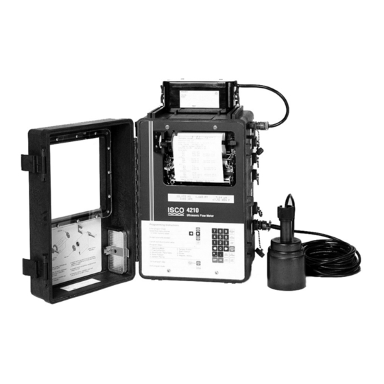
4210 Flow Meter Section 1 Introduction Figure 1-1 The 4210 Flow Meter 1.3 Compatible The 4210 Flow Meter may be used with the following equipment: Equipment Manufactured by Isco • 6700 Series Portable and Refrigerated Samplers • 3700 Series Sequential, Composite, and Refrigerated Samplers •... -
Page 17: Operating Principles
(weir or flume) or other open-channel flow arrangement where there is a known relationship between liquid level and flow rate. The 4210 can also measure flow in round pipes by using the Manning equation. The level-sensing device is an ultrasonic transducer. -
Page 18: Validity Tests And Error Display
(*) to indicate there is an error. 1.5.3 Ambient Air The ultrasonic measurement technique used in the 4210 Flow Temperature Factor Meter is based on the speed of sound in air. Figure 1-2 3012 Ultrasonic Level Sensor Since the speed of sound in air varies with temperature (approxi- mately 1% for 10°... -
Page 19: Software Upgrades
Figure 1-4 for a view of the connectors. 1.8 Technical The technical specifications for the 4210 are found in Table 1-2. Chart longevity for the 4210 internal printer is found in Table Specifications 1-3. -
Page 20: Controls And Indicators
4210 Flow Meter Section 1 Introduction Figure 1-3 4210 Controls and Indicators... -
Page 21: Side View Showing Connectors
4210 Flow Meter Section 1 Introduction Figure 1-4 4210 Side View Showing Connectors... - Page 22 4-pin, male M/S Connects ultrasonic level sensor to flow meter. Rain Gauge/ 9-pin female M/S Connects flow meter to an Isco Rain Gauge or YSI 600 YSI 600 Sonde Multi-Parameter Sonde. Also provides output to High Low Alarm (Custom) Relay Box.
- Page 23 4210 Flow Meter Section 1 Introduction Table 1-2 4210 Technical Specifications Physical and Electrical ⁄ ⁄ 16" high × 11 " wide × 10 " deep (41.9 cm × 29.2 cm × 26.7 cm) without power Size source. Weight 17 lb. 4 oz. (7.84 kg) Material High-impact molded polystyrene structural foam.
- Page 24 4210 Flow Meter Section 1 Introduction Isco FLOWLINK Data Storage and Retrieval System Memory Partitions Maximum of 6 user-defined memory partitions for level or event storage Data Storage Rate for data storage user-selected in 1, 2, 5, 10, 15, 30, 60, or 120 minute intervals.
-
Page 25: Chart Longevity
4210 Flow Meter Section 1 Introduction Table 1-3 4210 Chart Longevity Note Report Generator is turned off. Chart Speed, Inch/Hour Time to Empty Roll 195 Hours (8 Days) Days ⁄ Days 65 Days Table 1-4 Battery Life Expectancy Flow Meter Settings... -
Page 26: How To Make Battery Calculations
4210 Flow Meter Section 1 Introduction 1.9 How to Make Battery To calculate battery life expectancy for an installation, you must know two things: Calculations • The capacity of the battery you are using • The average current draw of the flow meter or (other device) powered Battery capacity is expressed in ampere-hours. -
Page 27: Calculating Current Draw
Always operate these batteries with a reserve factor. 1.9.1 Calculating Current Calculating current draw for a 4210 Flow Meter is somewhat Draw more difficult than calculating the battery capacity. You cannot simply measure the idle current of the unit unless the printer and report generator are turned off in the program. -
Page 28: Measuring Flow Meter Current
Figure 1-5 Measuring Flow Meter Current More information about batteries used to power Isco equipment is available from the Isco Power Products Guide, which is shipped with this manual and any flow meter order. 1-14... -
Page 29: Section 2 Programming
4210 Flow Meter Section 2 Programming Isco ships the flow meter with a program already installed called the default program. You can use this program as an example to see the flow meter's capabilities. Note that the default program is just to test the unit at the factory. -
Page 30: Keypad Functions
4210 Flow Meter Section 2 Programming Following is a typical programming display on the flow meter: (One of the items in the second line will be flashing. The item flashing is the selection currently held in memory.). TOTALIZED VOLUME UNITS •... -
Page 31: Programming Procedure
4210 Flow Meter Section 2 Programming Print Report – One function of the flow meter is to print reports of activity recorded on the flow meter at regular intervals. The contents of these reports are defined in step 1. If you set up the flow meter to generate these reports, you can have a report printed any time by pressing this key. - Page 32 4210 Flow Meter Section 2 Programming From time to time you will notice an arrow pointing to the edge of the display. This indicates that additional choices are available beyond what you can see on the display. By continuing to press the right arrow key you can view these unseen menu options.
-
Page 33: Description Of Program Steps
2.4.2 Step 2 - Flow FLOW CONVERSION TYPE determines how the flow meter cal- Conversion Type culates flow rate and total flow. For the 4210, flow rate is calcu- lated by knowing the measured level and (usually) the characteristics of a primary measuring device. - Page 34 Detailed information about many commonly-used primary mea- suring devices is provided in the Isco Open Channel Flow Mea- surement Handbook. This useful book provides formulas, flow rates at various levels, and values for maximum head, as well as much interesting descriptive material.
-
Page 35: Step 3 - Adjust Level, Parameters
19th-century Irish civil engineer. There is no primary measuring device as such. Instead the pipe, with considerations for its slope and internal roughness, serves as the primary device. The 4210 can calculate flow in round pipes, rectangular, U-shaped, or trap- ezoidal channels based on this formula. -
Page 36: Step 4 - Reset Totalizer
A brief description and specifications for the YSI 600 are printed in Appendix A. You may also contact the factory or your Isco rep- resentative. More information on the sonde is found in the YSI 600 Manual, shipped with each YSI 600 Sonde. -
Page 37: Step 6 - Sampler Enable
4210 Flow Meter Section 2 Programming FLOWLINK is Isco's proprietary data acquisition and man- agement software. FLOWLINK works with personal computers, modems, and laptop computers to monitor flow meters from a distance. Consult the factory for more details about FLOWLINK. -
Page 38: Step 7 - Alarm Dialout Mode
2.4.8 Step 8 - Printer The 4210 Flow Meter has a built-in printer. The printer is capable of plotting linear data along with printing alphanumeric (letters and numbers) messages. In this step you set the speed for ⁄... -
Page 39: Step 9 - Reports/History
50 history items and 200 sample events at a time. 2.5 Interpreting The Following are the program screens as they appear on the display of a 4210 Flow Meter. Explanations for most of the screens will Program Screens be provided. - Page 40 DO/PH READING INTERVAL refers to the measurement of spe- cific aspects of the flow stream other than amount. The 4210 sup- p o r t s m e a s u r e m e n t o f t h r e e d i f f e r e n t ch a r a c t e r i s t i c s : temperature, pH (the relative acidity or alkalinity of a solution), and D.O., dissolved oxygen.
- Page 41 D.O., temperature, plus conduc- tivity. Note If you are using the Isco D.O. sensor or are sensing D.O. with the YSI 600 Sonde, select as long a measurement interval as is practical for your application. The reasoning is that the D.O.
- Page 42 The Setup menu will reappear. This time select STATUS from the Setup menu. Press Enter. The following will appear: MODEL 4210 HW REV: XXXXXX SW REV X.XX ID XXXXXXXXXXX HW REV refers to the hardware revision number. SW REV refers to the software revision number.
- Page 43 D. O. You must have temperature with either pH or D. O. Note The 4210 cannot measure pH and D.O. at the same time unless you use the YSI sonde. Selection of one will prevent the other from appearing on the menus later.
-
Page 44: Optional Outputs
10-50 mA (not supported by the flow meter). Isco offers two different arrangements for the 4-20 mA control circuit. You can have either or both with the same flow meter. - Page 45 16 mA whether activated or not. While 4-20 mA applications are generally made in installations with com- mercial power available, Isco suggests the following for those who have a 4-20 mA output in a battery-powered installation.
- Page 46 4210 Flow Meter Section 2 Programming MANUAL CONTROL will appear if you continue moving to the right. “RANGE” will appear with the ANALOG OUTPUT menu if the optional internal 4-20 mA converter is present in the flow meter. If you select RANGE, the following will appear: OUTPUT RANGE •...
-
Page 47: Serial Output Codes
Serial Output (INTERROGATOR) port. An Interrogator cable may be required. Contact Isco technical support for more information. Command Line – The lines of text contain the port values for each port that is turned on. - Page 48 4210 Flow Meter Section 2 Programming Table 2-1 ASCII Output Codes (Continued) Parameter Units Code YSI 600 Conductivity Millisiemens per centimeter YSI 600 Specific Conduc- Millisiemens per centimeter tance YSI 600 Salinity Parts per thousand YSI 600 Total Dissolved Milligrams per liter...
-
Page 49: Periodic Output
4210 Flow Meter Section 2 Programming tips. (See Rain Gauge, page 2-26.) The port values appear in a comma-separated values format. Each data field is preceded by a two or three-character type identifier. The table lists the type identifiers. Note that the flow meter’s current time and the sample event time stamp appear as a number in standard spreadsheet format (days since 1900). -
Page 50: Report Setup
4210 Flow Meter Section 2 Programming If you select any of these outputs, the flow meter will request that you turn them on or off. If you are running on battery and do not need these options, select OFF. Otherwise, select ON. After the OPTIONAL OUTPUTS menus have been set, press Enter. -
Page 51: Other Setup Options
4210 Flow Meter Section 2 Programming Select YES if you want DO/PH to appear in the report. You must have the appropriate sensor connected to the flow meter. It is capable of sensing temperature, pH and temperature, and D.O. (dissolved oxygen) and temperature. The following will appear: TEMPERATURE IN REPORT •... - Page 52 4-2-1-0 for the 4210. If you select ON, there is a time-out before the lock engages. If you continue to work through the rest of the program, the lock will not engage until you are done.
- Page 53 4210 Flow Meter Section 2 Programming Press Enter and the SETUP menu will reappear. SELECT OPTION • PROGRAM • • SETUP • PROGRAM will be flashing. (Note that PROGRAM is always the default choice. That is because you are more likely to need to make changes in the PROGRAM section of the software than in the SETUP section.)
-
Page 54: Additional Parameters
• pH • • NOT MEASURED • pH measurement determines the relative acidity or alkalinity of a solution. You must have an Isco pH Probe (or approved equiv- alent) connected to the flow meter through the parameter port to sense pH. pH measurements range from 0 to 14 pH units, with solutions below 7 considered acidic and solutions above 7, alkaline. -
Page 55: The Ysi 600 Multi-Parameter Sonde
Some dissolved oxygen is necessary for the survival of aquatic life in these waters. You must have an Isco Dissolved Oxygen Probe (or approved equivalent) to sense dissolved oxygen. The probe attaches to the Parameter Port. - Page 56 4210 Flow Meter Section 2 Programming time. The YSI 600 Sonde attaches to the Rain Gauge connector on the 4210. Note that this connector must be a special, modified connector with nine pins. Note 4210 Flow Meters with 4-pin Rain Gauge connectors cannot support the YSI 600.
- Page 57 4210 Flow Meter Section 2 Programming Note The flow meter cannot communicate at 600 baud. If your sonde has been set up for 600 baud, you will get a communi- cations failure. Consult the YSI 600 Manual for what to do in this case.
-
Page 58: Step 2 - Flow Conversion
Conversions TYPE OF DEVICE: • WEIR • • FLUME • For detailed information on weirs and flumes, refer to the Isco Flow Measurement Handbook that was shipped with your flow meter. Consulting the manufacturer of the specific weir or flume is also worthwhile. - Page 59 4210 Flow Meter Section 2 Programming :Also available with the arrow key: SELECT TYPE OF FLUME • HS • • H • • HL • • TRAPEZOIDAL If you select PARSHALL for the type of flume, the following will appear: SELECT PARSHALL SIZE: •...
-
Page 60: Equation
For example: 0.01 -------- - Roughness coefficients are published in the Isco Open Channel Flow Measurement Handbook. You must know the material the pipe is made of. The roughness coefficients are published for all common materials in three grades: minimum, normal, and maximum. -
Page 61: Data Points
Data Point flow conversion allows you to enter measured level and flow rate values for a number of different points. The 4210 Flow Meter can accept up to four sets of data points with each set containing as many as fifty points. -
Page 62: Maximum Head
The common use of data point flow conversion is with unusual primary mea- suring devices, specifically devices that the 4210 does not support in the WEIR/FLUME flow conversion set. The level-to-flow rate data for such devices is usually available from the manufacturer. -
Page 63: Programming The 4-20 Ma Outputs
4210 Flow Meter Section 2 Programming Instead, use the value that is the largest expected level for your actual situation, even if this is less than the published maximum. The flow meter's internal resolution and its accuracy are based on the value you enter for Maximum Head. The flow meter will... -
Page 64: Step 3 - Parameter To Adjust
4210 Flow Meter Section 2 Programming full-scale value of four feet. If the actual level reading is cur- rently two feet, the analog output would read 12 mA (50% if the 4-20mA current range is selected) or 10 mA (50% if the 0-20 mA current range is selected). - Page 65 4210 Flow Meter Section 2 Programming Note It is very important to enter accurate measurements for both the level in the stream and the dimension(s) of the channel, as all calculations of flow will be based on these measurements. If...
- Page 66 4210 Flow Meter Section 2 Programming If you select ABS (absolute) BAROMETRIC PRESSURE the fol- lowing will appear: ABS BAROMETRIC PRESSURE X.XX mmH Absolute barometric pressure is barometric pressure not corrected to sea level. The barometric pressure published by the U.S. Weather Bureau is corrected to sea level. If you use their value, you must convert it to the absolute pressure for your altitude.
- Page 67 • D.O. STANDARD• •ABS BAROMETRIC PRESSURE •> ALTITUDE is just off screen to the right. Programming for YSI 600 D.O. is essentially the same as that described for the Isco D.O. sensor on the preceding section, with the exception that you always place the sensor in a cup, rather than wrap a moist cloth around it, as is done for the Isco D.
-
Page 68: Ysi 600 Sonde Calibration Flow Chart
4210 Flow Meter Section 2 Programming Figure 2-2 YSI 600 Sonde Calibration Flow Chart 2-40... -
Page 69: Step 4 - Reset Totalizer
2.9 Step 4 - Reset Totalizer This step allows you to reset the flow meter's internal flow totalizer. The 4210 can also maintain a separate totalizer for the time the sampler is enabled through the sampler enabling feature (step 6). If you select step 4, the following screen will appear. - Page 70 4210 Flow Meter Section 2 Programming If you select CONDITIONAL for sampler pacing, the following will appear: CONDITION • (LEVEL) • • (FLOW RATE) • • (RAINFALL) • • (D. O.) • • (pH) • (TEMPERATURE), (YSI pH), (YSI DO), (YSI CONDUCTIVITY) and (YSI TEMP) may also appear.
-
Page 71: Step 6 - Sampler Enable
4210 Flow Meter Section 2 Programming SELECT OPERATOR allows you to trigger the sampler from a single condition or from two conditions. Suppose you wanted to trigger the sampler from only one condition, level. You would select LEVEL as the condition, and then identify what change in LEVEL would be the trigger. - Page 72 RAINFALL. Third, enter an amount of time over which the rainfall occurs. Finally, you enter a time since the last rainfall. You must have an Isco Rain Gauge, or approved equal, to measure rainfall. The following menus are the STORM...
- Page 73 4210 Flow Meter Section 2 Programming menus that do appear will depend on the flow meter type and selections made earlier in the program. At least one of the condi- tions will be available to you. If you select LEVEL from CONDITION the following will appear: LEVEL •...
-
Page 74: Step 7 - Alarm Dialout Mode
4210 Flow Meter Section 2 Programming outside of “normal.” If the enabling condition returns to “normal,” the sampler enable will turn off until the next time the condition goes outside of “normal.” In the latching mode, the sampler will be enabled the first time... - Page 75 4210 Flow Meter Section 2 Programming Followed by: RAINFALL AMOUNT X.XX INCHES (or other units of measure) Then: RAINFALL TIME PERIOD • 15 MIN • • 30 MIN • • 1 HR • • 2 HR • • 4 HR •...
- Page 76 4210 Flow Meter Section 2 Programming If you want either of two conditions to trigger an alarm, select If you want both of two conditions to be met before signalling an alarm, select AND. Selection of DONE will advance you to the next display menu.
-
Page 77: Step 8 - Printer Setup
4210 Flow Meter Section 2 Programming 2.13 Step 8 - Printer Setup This step sets up the operation of the flow meter's internal printer. This printer also functions as a plotter. Note that the printer/plotter is capable of printing alphanumeric information (words and numbers), and at the same time, plotting linear data like flow, level, pH, etc. - Page 78 PLOT RAINFALL ON CHART? • NO • • YES • You must have an Isco 674 Rain Gauge or equivalent connected to the flow meter to measure rainfall. Output is recorded in either inches or millimeters. Note that there is only one over-range for rainfall.
-
Page 79: Step 9 - Reports/History
4210 Flow Meter Section 2 Programming 2.14 Step 9 - This step lets you set up the flow meter to print periodic reports. The typical report contains such information as the period of Reports/History time covered in the report, maximum and minimum levels, and when they occurred. - Page 80 4210 Flow Meter Section 2 Programming After you have entered the desired date and time for the first report, the program will advance to the following: PRINT FLOW METER HISTORY • YES • • NO • The final programming choice is HISTORY. This presents a record of the programming activity on the flow meter that you can have printed by the plotter.
-
Page 81: Section 3 Installation
4210 Flow Meter Section 3 Installation This section of the manual tells you how to install the 4210 Flow Meter. There is also information on mounting methods, intercon- nection wiring, and the setup procedure. 3.1 Preparation for Use Isco ships the flow meter with a roll of paper installed and a default program entered into memory. -
Page 82: Connection To A Power Source
3.2 Connection to a Power The 4210 requires a 12 volt, direct current (12 VDC) power input. This power may come from various sources. Source •... -
Page 83: Isco Nickel-Cadmium Battery
Battery battery to power the flow meter. Isco packages this battery spe- cifically for use with Isco flow meters and samplers. Refer to the Power Products Guide accompanying this manual for detailed information about this battery and the procedure for charging it. -
Page 84: Ac Power Supplies
However, you will have to mount batteries of this type separately, as they are too large to fit on top of the flow meter. Isco offers a special optional connect cable to power the flow meter from a separate battery. -
Page 85: Flow Meter Mounting And Installation Procedures
4210 Flow Meter Section 3 Installation 3.3 Flow Meter Mounting Because the 4210 Flow Meter is a portable device, it may or may not be permanently installed. You can suspend the flow meter in and Installation temporary installations, such as sewers, or mount it perma- Procedures nently in other installations, such as treatment plants. -
Page 86: Safety Considerations
WARNING The 4210 Flow Meter has not been approved for use in “hazardous locations” as defined by the National Electrical Code. - Page 87 Noise – Background noise can interfere with the operation of the flow meter. You must filter this noise out, or the flow meter may trigger on noise rather than the echo. The 4210 uses a tuned circuit to filter unwanted noise outside the operating frequency.
-
Page 88: Accessories
Wavelength – You can determine the wavelength of sound by dividing the velocity of the sound by the frequency. The fre- quency of the 4210 is about 40 kHz. The length of a 40 kHz sound wave is found by dividing 1,125 by 40,000 which is 0.02815 feet or 0.3378 inches. -
Page 89: Ultrasonic Level Sensor: Mounting Considerations
Extension Cable – Isco offers a 25 foot (7.6 m) extension cable to connect to the ultrasonic level sensor. Do not attempt to cut or splice cable lengths. Coil any extra cable neatly by the flow meter. -
Page 90: Dead Band
" male pipe thread with a conduit lock nut to connect it to a mounting bracket or cable stiffener. An optional mounting bracket is available from Isco to mount the ultrasonic level sensor. You can also run the ultrasonic level sensor cable through conduit to the flow meter. -
Page 91: Ultrasonic Level Sensor Dead Band
MAXIMUM HEAD “Hmax”: is the maximum level that the DISTANCE “D” is the distance from the level sensor to the liq- flow meter can measure. For the 4210, this is limited to 21 feet uid surface. For the 4210, distance can be from 2 to 12 feet. -
Page 92: Mounting The Ultrasonic Level Sensor
4210 Flow Meter Section 3 Installation Figure 3-4 Mounting the Ultrasonic Level Sensor 3-12... -
Page 93: Mounting The Ultrasonic Level Sensor (Continued)
4210 Flow Meter Section 3 Installation Figure 3-5 Mounting the Ultrasonic Level Sensor (Continued) 3-13... -
Page 94: Suspension Of The Sensor
3.6.9 Minimizing Level In order to minimize measurement errors with the 4210 Flow Measurement Errors Meter, the following precautions should be observed in the instal- lation of the ultrasonic level sensor. - Page 95 4210 Flow Meter Section 3 Installation approximate order of their significance. Factors affecting accuracy of the ultrasonic technique were discussed in the beginning of this section. Avoid Temperature Differences – Avoid installations where the ultrasonic level sensor will operate at a different temper- ature than the air between the level sensor and the flow stream through which the ultrasonic beam passes.
- Page 96 4210 Flow Meter Section 3 Installation lating the velocity of sound in the air is multiplied by the dis- tance from the level sensor to the surface of the flow stream. Minimizing the distance will minimize the error. Calibrate at Expected Temperature – The user should cali- brate the level reading under temperature conditions as near as possible to those expected during operation.
-
Page 97: Foam And Oil On The Surface Of The Stream
4210 Flow Meter Section 3 Installation FOAM Figure 3-6 Foam and Oil on the Surface of the Stream Figure 3-7 Small Pipes and Narrow Channels 3-17... -
Page 98: Alternative Flow Measurement Systems
4210. 3.7.1 Isco Sampler One of the uses of the 4210 Flow Meter is to control a sampler in a flow-paced sampling mode. Flow-paced sampling means that the flow meter is programmed to signal the sampler to take a sample after a specific volume of flow has passed through the flow stream, rather than after a period of time. -
Page 99: Section 4 Optional Equipment
4200 Series Flow Meter. Application-specific options are covered in the Installation sections of each type of flow meter. Isco offers the following options for use with all 4200 series flow meters: • 4200T Modem •... -
Page 100: Modem And Flowlink Software
Disconnect the interroga- tor cable in order to use the 4200T Modem. 4.2.2 Modem and The 4200T Modem communicates with Isco's FLOWLINK data FLOWLINK Software storage and acquisition software, setting up the flow meter to collect blocks of data. -
Page 101: Types Of Service
“If trouble is experienced with this equipment, please contact the Isco Customer Service Depart- ment, (800) 465-3022 or outside the U.S.A., call (402) 464-0231, 4700 Superior Street, Lincoln Nebraska, 68504, for repair and (or) warranty information. If... -
Page 102: Connection To An External Serial Device
This option (SERIAL OUTPUT) is discussed in detail in Section 2.6.2. Isco still offers the older 300 baud output for the 2312 Plotter (no longer sold), also on the RAIN GAUGE connector. This port pro- vides ASCII level and flow rate data for remote transmission to any ASCII-compatible equipment. -
Page 103: To 20 Ma (Analog) Outputs (External And Internal)
4 mA becomes the 0%, or baseline for the condition, while 20 mA becomes the 100%, or full-scale of the condition. Isco offers two different arrangements for providing the 4-20 mA outputs. One is an external box that converts the signals from the flow meter to a 4-20 mA current loop. -
Page 104: The Internal Analog Output Board
Maximum Distance 1,500 ft. (457.3 m) using 18 AWG wire. 4.5 The Internal Analog For those needing more than one analog output, Isco offers the Multiple Analog Output Board, which is installed inside the Output Board flow meter. This board provides from one to three isolated analog outputs. -
Page 105: Internal 4-20 Ma Specifications
4210 Flow Meter Section 4 Optional Equipment • Use a larger battery: either a commercial deep-cycle/marine type, or an Isco 35 Ampere-hour lead-acid battery. • Order and use only one analog output. • Flow meter program choices also affect power consumption. -
Page 106: Tipping Bucket Rain Gauge
4210 Flow Meter Section 4 Optional Equipment 4.6 Tipping Bucket Rain A Tipping Bucket Rain Gauge is available from Isco for use with 4200 Series Flow Meters. The gauge connects to the flow meter Gauge by a cable terminated in an M/S connector. This connector plugs into the Remote Printer/Rain Gauge connector on the case. -
Page 107: Isco Flowlink Software
(or reduces capacity approximately 25%). In alarm condition, one alarm box will com- pletely discharge a fresh (4 Ah) battery in 21 hours. Isco recom- mends using only one alarm box in a battery - powered installation, and you can expect to change the battery more often. -
Page 108: Installation
Flow Meter Meter requires a cable and an M/S connector. A special cable, 25 feet long, is available from Isco. On one end of the cable is a 4-pin, male M/S connector. Plug this connector into the Remote Plotter/Rain Gauge connector on the flow meter. The other end of the cable has 3 stripped wires. -
Page 109: The Temperature Probe
Module and the D.O. probe connects to the 270 D.O. Module. The modules are not interchangeable. Isco flow meters are built with one parameter sensing port, and can only sense temperature plus one parameter at a time, (unless you use the YSI Sonde). You must select temperature, D.O. with temperature, or pH with temperature. -
Page 110: The Ph Probe
4210 Flow Meter Section 4 Optional Equipment 4.10 The pH Probe The pH probe measures the acidity or alkalinity of an aqueous solution by determining the relative quantity of dissociated hydrogen ions, H (actually H ) in the solution. A larger... -
Page 111: Ph Probe Calibration
The potential, when read by a sensitive voltmeter, translates into a reading of pH. With an Isco flow meter, the voltage is sent first to a preamplifier inside the probe to reduce the impedance of the circuit and improve the signal-to-noise ratio, and then on to the parameter module to allow greater operating distance from the flow meter. -
Page 112: Ph Probe Installation Guidelines
4210 Flow Meter Section 4 Optional Equipment Flow streams with a high grease content will coat the sensing surfaces of the probe quickly, clogging them and slowing the response time or stopping it altogether. Installation in very greasy flow streams is not recommended. - Page 113 For horizontal mounting, the probe fastens to a sensor carrier that snap-fits to an Isco mounting ring. The mounting rings fit various diameters of round pipes 15" diameter and smaller. For larger pipes, use the Isco Scissors Ring. For installation details, refer to the instruction sheet supplied with the mounting ring.
-
Page 114: Ph Probe Life
4.0 buffer solution. Never store the probe dry or without the cap in place. The Isco amplifier box extends the allowable distance between the probe and the flow meter. The probe has a 25-foot cable, so you must mount the amplifier within this distance. -
Page 115: Storage And Maintenance Of Ph Probes
4210 Flow Meter Section 4 Optional Equipment Figure 4-5 pH Parameter Module 4.10.5 Storage and If you remove the pH probe from operation, be careful to keep the Maintenance of pH glass sensor bulb wet. Always store the probe with the rubber Probes cover screwed completely over the threaded end of the sensor. -
Page 116: The Dissolved Oxygen (D.o.) Probe
• Frequent maintenance is necessary when the probe is installed in flows with grease or solids content. Tests conducted by Isco with probes installed in various waste streams indicate that grease and solids quickly coat the probe's membrane, making it impossible for oxygen to enter the reaction chamber. -
Page 117: How The D.o. Probe Works
4210 Flow Meter Section 4 Optional Equipment tends to drive the solids further into the membrane pores. You must usually replace both the electrolyte and the membrane to get an accurate reading. In severe cases of fouling it may be necessary to change the membrane very frequently, even as often as every other day. -
Page 118: Membrane Thicknesses
Place a piece of moist tissue inside the bottle, and slide the bottle over the probe. 4.11.3 Membrane Isco supplies a 2 mil (.002") thick membrane for use with the Thicknesses D.O. probe. This membrane is recommended for long-term moni- toring situations only, typical of our users' applications. - Page 119 (which can result from extended use with a loose or wrinkled membrane), you need to restore its surface. You can return it to Isco or clean it yourself with a probe reconditioning kit. (This kit is available from Isco.) Never use chemicals or any abrasive not supplied with this kit.
-
Page 120: Calibrating The D.o. Probe
Probe with electrolyte and seat the membrane). Note You must use the Isco Temperature Probe with the D.O. Probe to provide temperature compensation. 2. Wrap both the D.O. Probe and the Temperature Probe in a damp cloth. Wait ten minutes for them to stabilize, then proceed. - Page 121 4210 Flow Meter Section 4 Optional Equipment 3. Go to step 1 on the flow meter. Select PROGRAM, then step through the units of measure with Enter until you reach the menu for pH measurement. 4. Select NOT MEASURED. Press Enter. Then D.O. UNITS will appear.
-
Page 122: Installation Of Parameter Probes In Round Pipes
Figure 4-8 Spring Ring (15” and Under) 4.12.2 Pipes Larger Than 15” For pipes 18 inches in diameter and larger, Isco offers the adjustable Universal Mounting Ring. This device consists of two or more metal strips that lock together with tabs to form a single assembly. -
Page 123: U-Channel Mounting
4210 Flow Meter Section 4 Optional Equipment 4.12.3 U-Channel Mounting It is possible to mount a probe in a U-channel, but you would not be able to use the complete Universal Mounting Ring. You would use the base section only and attach it to the U-channel surface with studs fired from a power-activated stud gun. -
Page 124: Installation Of The Spring Ring
4210 Flow Meter Section 4 Optional Equipment Extensions Scissors Assembly Base Section Tightening scissors assembly expands ring to press firmly against wall of pipe, securing ring. Figure 4-9 Universal Mounting Ring 4.12.5 Installation of the After the probe has been attached to the mounting ring, the Spring Ring actual installation procedure is fairly simple. -
Page 125: Installing The Universal Mounting Ring
4210 Flow Meter Section 4 Optional Equipment CAUTION The mounting ring may need anchoring. Under conditions of high velocity (greater than five feet per second or 1.5 meters per second), the mounting ring may not have sufficient out- ward spring force to maintain a tight engagement with the pipe. -
Page 126: Universal Mounting Ring Components
4210 Flow Meter Section 4 Optional Equipment 7.5" 20" Extension 1 30" 68-3000-038 (pair) 40" 47.1" Extension 2 68-3000-039 (pair) Extension 3 68-3000-040 (pair) Scissors Mechanism 60-3004-170 Extension 4 Standard Base 68-3000-041 Section (pair) 60-3004-169 The Following Table Indicates Recommended Part Configuration For Various Pipe Diameters. -
Page 127: The Ysi 600 Multiple Parameter Sonde
4210 Flow Meter Section 4 Optional Equipment 4.13 The YSI 600 Multiple The YSI 600 Sonde is a multi-purpose, water quality mea- surement and data collection system. It is intended for use in Parameter Sonde research, assessment, and regulatory compliance. The YSI 600 Sonde can measure the following water qualities: •... -
Page 128: Ysi 600 Technical Specifications (Complete Unit)
4210 Flow Meter Section 4 Optional Equipment The YSI 600 is available with a cable 25 feet long to connect to the flow meter. The cables are waterproof at the sonde and can be used in lab or field. Information about programming the flow meter to use the YSI 600 is found in Section 2 of this manual. - Page 129 4210 Flow Meter Section 4 Optional Equipment Table 4-6 YSI Sensor Technical Specifications Dissolved Oxygen, mg/L Sensor Type Calculated from % air saturation, tem- perature, and salinity Range 0 to 20 mg./L Accuracy ± 0.2 mg./L Resolution 0.01 mg./L Conductivity*...
-
Page 130: Mechanical Totalizer
4210 Flow Meter Section 4 Optional Equipment 4.14 Mechanical Totalizer A mechanical totalizer is available for 4200 series flow meters that consists of a seven-digit, non-resettable mechanical counter mounted in the front panel. It must be ordered with the flow meter. -
Page 131: Section 5 Maintenance And Service
4210 Flow Meter Section 5 Maintenance and Service This section of the 4210 instruction manual provides detailed instructions on the care and routine maintenance necessary to keep the flow meter in top operating condition. Included are sec- tions on cleaning the flow meter, reactivating the desiccator, maintaining the ultrasonic level sensor, and servicing the internal printer. -
Page 132: Checking And Regenerating The Desiccant
(pins or jacks) inside the con- nectors; residue from the sprays could cause intermittent or failed contacts. 5.1.4 Checking and As shown in the picture, the 4210 is equipped with a reusable Regenerating the desiccating canister attached by a spring steel clamp attached to Desiccant the inside of the flow meter's lid. -
Page 133: Care Of The Ultrasonic Level Sensor
4210 Flow Meter Section 5 Maintenance and Service Figure 5-1 Location of the Internal Desiccant Canister CAUTION Do not allow the flow meter to operate with a saturated desic- cant canister. In many flow environments, gases are present in the atmosphere that can combine with available water vapor to form acids. -
Page 134: Maintenance Of The Printer
4210 Flow Meter Section 5 Maintenance and Service 5.2 Maintenance of the The internal printer needs little maintenance beyond changing the chart roll and the ink ribbon. Refer to the pictures provided Printer for each section. Also refer to the label inside the cabinet. -
Page 135: Ink Ribbon Replacement
4210 Flow Meter Section 5 Maintenance and Service 9. Line up the slots in the cardboard tube with the raised guides on the spool. 10. Reattach the white end cap by wedging the two catches on the end of the spool into the two slots on the white end cap. -
Page 136: Do Not Lubricate Or Disassemble
Isco recommends no attempt be made to oil or disassemble the mechanism should it malfunction. Oil attracts dirt; some oils become gummy over a period of time and may cause parts of the mechanism to bind or stick. -
Page 137: Running Update
This instruction sheet assumes that you have a cable to connect the computer to the instrument. If you do not, you can order one from your Isco sales representative, or from the factory. The part number is on the back of this page. -
Page 138: Setting Preferences For Flash Update
4210 Flow Meter Section 5 Maintenance and Service Figure 5-3 Flash Update: File Selection The window in Figure 5-3 above appears only when the directory or disk contains more than one version of the update files and the Preferences option for Show Update File is “All Update Files.” It lists the update files in the directory. -
Page 139: Flash Update: Minimum Requirements
(Must operate at 19,200 baud when communicating through the serial port.) 640 kilobytes RAM (Random Access Memory), minimum Serial port For connecting the computer to Isco flow meters, flow log- gers, or samplers. Keyboard Any compatible keyboard Hard disk Not required. -
Page 140: Servicing And Troubleshooting
4210 Flow Meter Section 5 Maintenance and Service 5.4 Servicing and This section of the 4210 instruction manual provides servicing information and a troubleshooting guide to assist you in cor- Troubleshooting recting certain minor malfunctions that might occur. Included are sections describing disassembly of the unit, on fuse replacement, and on the care and repair of CMOS circuitry. -
Page 141: Display Warnings
Pressing 4 and Exit Program when powering up will cause most programmed entries to be lost. Accumulated data stored in the 4210 will also be lost. The flow meter will revert to the program originally entered at the factory. If this operation is performed, it will be necessary to reprogram the unit to user specifications. -
Page 142: Processor Servicing
- cially-designed equipment necessary for timely, efficient repair of the 4210 Flow Meter. If you still wish to attempt repairs, the Isco Customer Service Department is available to provide additional advice and information on servicing. -
Page 143: Precautions For Servicing Cmos Circuitry
11. Check the reset circuitry to see that it is working properly. 5.5 Precautions for Most of the circuitry in the 4210 Flow Meter is made up of CMOS Servicing CMOS components. Because of the oxide gate structure of these devices,... - Page 144 4210 Flow Meter Section 5 Maintenance and Service • Never perform any work in a room with a carpeted floor. • Always roll up work clothes' sleeves so that the arms are in contact with the working surface. • Avoid using a work surface made of an extremely good insulator.
-
Page 145: Replacement Parts
4210 Flow Meter Appendix A Replacement Parts List A.1 Replacement Parts The following section contains illustrations and corresponding tables of 4210 Flow Meter replacement parts. A list of accessories and optional equipment can be found at the end of this section. - Page 146 4210 Flow Meter Appendix A Replacement Parts List...
- Page 147 4210 Flow Meter Appendix A Replacement Parts List...
-
Page 148: A-1 4210 Flow Meter Replacement Parts List
4210 Flow Meter Appendix A Replacement Parts List Table A-1 4210 Flow Meter Replacement Parts List Part Number Complete Parts Description 60-3214-139 Motor Assy Chart Drive 4200 60-3214-093 LCD Module Assy B/L 60-3214-136 Case Bottom Sub Assembly 60-3214-098 PCB Assy Keyboard... - Page 149 4210 Flow Meter Appendix A Replacement Parts List Table A-1 4210 Flow Meter Replacement Parts List (Continued) Part Number Complete Parts Description 109-0609-00 Cabinet Catch White 142-2003-00 Component Clip " 149-1000-00 Amp Dust Cover 9760-10 149-1001-00 Amp Dust Cover MS9760-14...
-
Page 150: Accessories
Flow Data Handbook........................ 60-3003-041 Ultrasonic Wall Mount ......................60-2443-092 4210 Flow Meter Only......................60-3214-089 4210 Accessories 4210 Flow Meter Instruction Manual ..................60-3214-110 4210 Flow Meter Pocket Guide....................60-3213-254 Ultrasonic Transducer ......................60-3114-012 Ultrasonic Transducer Extension Cable (25 ft. [7.6 m])............60-3114-013 (Other lengths available by special order only.) - Page 151 YSI 600 and Isco 674 Rain Gauge Y-Connect Cable............... 60-0604-002 (This cable allows use of the YSI 600 Sonde and the Isco 674 Rain Gauge at the same time.) Use the following with Isco Mounting Rings in Round Pipe Installations Probe Carrier for Temperature probe ..................
-
Page 152: Universal Mounting Ring
4210 Flow Meter Appendix A Replacement Parts List Universal Mounting Ring (for pipes 18” diameter and larger) Base Section (with tabs for mounting up to three probes) ............60-3004-171 Scissors Assembly........................60-3004-170 Extension 1 (7.5”) ........................60-3004-172 Extension 2 (20”) ........................60-3004-173 Extension 3 (30”) ........................ -
Page 153: Appendix B Programming Worksheet
• Use a photocopy of the worksheet on the following pages to create a hard copy of the program you use in your 4210. Most program steps can be completed in the shop without the flow meter being installed or at the job site. - Page 154 4210 Flow Meter Appendix B Programming Worksheet Step 1 - Setup 1. Select Option: Program, Setup. First, choose Setup and work through the following menus. 2. Year:Month:Day:Hour:Min ____________________________ 3. Site I.D. _______ (Any three-digit number) 4. Measurement Setup: Level Reading Interval, Minimum Depth, Do/pH Reading Interval ________________________ 5.
- Page 155 4210 Flow Meter Appendix B Programming Worksheet 34. Temperature In Report: Yes, No________________________ 35. YSI 600 Data in Report: Yes, No _______________________ 36. Sample History In Report: Yes, No _____________________ 37. Setup Options: Status, Report Setup, LCD Backlight ____ 38. LCD Backlight Mode: Timeout, Continuous, Off _________ 39.
- Page 156 4210 Flow Meter Appendix B Programming Worksheet 14. HL Flume Size: 2.0', 2.5', 3.0', 3.5', 4.0 __________________ 15. Leopold-Lagco Flume Size: 4", 6", 8", 10", 12", 15", 18", 21", 24”, 30” 16. Enter Equation Units: Q = ___.___H^___ + ___.___H^___...
- Page 157 Installations generally use either the Isco parameter probes or the YSI 600 Sonde, but not both. Use the following menus for either the Isco probes or the YSI 600 Sonde. Steps 3, 4, and 5 can be used for both 2 and 3-point pH calibrations.
- Page 158 4210 Flow Meter Appendix B Programming Worksheet 11. Place Probe In ______Ms/cm. (or ppt) Press Enter When Stable: _______Ms/cm (job site only) 12. YSI 600 Dissolved Oxygen Calibration: D.O. Standard, Absolute Barometric Pressure, Altitude Step 4 - Reset Totalizer 1. Reset Totalizer: Yes, No _______________________________ 2.
- Page 159 4210 Flow Meter Appendix B Programming Worksheet 4. Rainfall Time Period: 15 Min, 30 Min, 1 Hr, 2 Hr, 4 Hr, 6 Hr, 8 Hr, 12 Hr, 24 Hr, 48 Hr, 72 Hr 5. Time Since Last Rainfall: Days: ______ (allowable 1-7) 6.
- Page 160 4210 Flow Meter Appendix B Programming Worksheet Additional tables for Data Point Entry Data Point Set .#2. Level Flow Level Flow Level Flow Level Flow Data Point Set #3. Level Flow Level Flow Level Flow Level Flow...
- Page 161 4210 Flow Meter Appendix B Programming Worksheet Data Point Set #4 Level Flow Level Flow Level Flow Level Flow Notes...
- Page 162 4210 Flow Meter Appendix B Programming Worksheet B-10...
-
Page 163: Appendix C General Safety Procedures
4210 Flow Meter Appendix C General Safety Procedures The safety of the personnel who use the 4210 is a critical consid- eration. The following procedures, applicable to working in and around manholes and sewers, are those used by Black & Veatch, a respected consulting firm, and are published here by their per- mission. -
Page 164: Deteriorated Rungs
4210 Flow Meter Appendix C General Safety Procedures C.1.2 Deteriorated Rungs Manhole steps may be corroded and not strong enough to support a man. It may be difficult to inspect the rungs because of poor lighting. C.1.3 Traffic Whenever manholes are located in the traveled way, barricades and warning devices are essential to direct traffic away from an open manhole. -
Page 165: Traffic Protection
4210 Flow Meter Appendix C General Safety Procedures thing in their hands as they enter the manhole, to ensure that their hands will be free to hold on or grab if they slip. A good method for entering a manhole is to sit on the surface facing the manhole steps or ladder, with the feet in the hole and the arms straddling the opening for support. -
Page 166: Emergencies
4210 Flow Meter Appendix C General Safety Procedures • Wear a safety harness with a stout rope attached. • Do not smoke. • Avoid touching yourself above the collar until you have cleaned your hands. C.4.4 Emergencies Every member of the crew should be instructed on procedures to be followed in cases of an emergency. - Page 167 4210 Flow Meter Appendix C General Safety Procedures “People in good health are not afraid to drive over the high passes in the Rocky Mountains. At Loveland Pass, oxygen pressure is 13.2% of a normal atmosphere. At the top of Mt.
-
Page 168: C-1 Hazardous Gases
4210 Flow Meter Appendix C General Safety Procedures “Remember that the nose fails, too, when it comes to sensing dangerous concentrations of H “Various other toxic gases have been mentioned in some publica- tions. It is unlikely that any person has been asphyxiated in a sewer by any of those other gases, except possibly chlorine. - Page 169 4210 Flow Meter Appendix C General Safety Procedures Table C-1 Hazardous Gases (Continued) Carbon Asphyxiant, Colorless, 1.53 Cannot be endured at 40,000 5,000 — — At bottom; Products of Oxygen Dioxide odorless. When 10% more than a few when heated...
- Page 170 4210 Flow Meter Appendix C General Safety Procedures Table C-1 Hazardous Gases (Continued) Methane Simple asphyxiant. 0.55 Acts mechanically to Probably — 5.0 15.0 At top, increas- Natural gas, 1. Combustible Colorless, odorless, deprive tissues of oxy- no limit, ing to certain...
-
Page 171: Appendix D Material Safety Data Sheets
4210 Flow Meter Appendix D Material Safety Data Sheets Material Safety Data Sheets for the desiccants used in the 4210 flow meter can be found on the following pages. For more infor- mation about these chemicals, contact the manufacturers listed... - Page 172 4210 Flow Meter Appendix D Material Safety Data Sheets Indicating Silica Gel Material S afety Data S heet Identity (Trade Name as Used on Label) Manufacturer MULTISORB TECHNOLOGIES, INC. MSDS Number* : (formerly Multiform Desiccants, Inc.) Address: 325 Harlem Road...
- Page 173 4210 Flow Meter Appendix D Material Safety Data Sheets Page 2 S ec tion 5 - Health Hazard Data P R IMAR Y R OUT E S Inhalation Ingestion C AR C INOG E N OSHA OF E NTR Y...
- Page 174 4210 Flow Meter Appendix D Material Safety Data Sheets...
- Page 175 4210 Flow Meter Index Numerics 4-20 mA Outputs, 2-35, 4-5 Maintenance Case, 5-1 Desiccant, 5-2 Level Sensor, 5-3 Accessories, 3-8 Printer, 5-4 Accessory Parts, A-6 Software Updates, 5-6 Alarm Box, 4-9 Mounting Alarm Dialout, 2-46 Flow Meter, 3-5 Analog Outputs, 2-35, 4-5...
- Page 176 4210 Flow Meter Index Rain Gauge, 4-8 Replacement Parts, A-1 Reports, 2-22, 2-51 Safety Information, C-1 Sampler Enable, 2-43 Sampler Pacing, 2-41 Servicing Assistance, 5-11 CMOS Circuitry, 5-13 Fuses, 5-10 Microprocessor, 5-12 Software Reset, 5-11 Updates, 5-6 Specifications, 1-9 Spring Rings, 4-24...
- Page 177 Compliance Statements NOTICE Disregard the following “Declaration of Conformity” and Radio Interference Statement” if your instrument does not have a CE label on its rear panel Radio Interference Statement This equipment has been tested and found to comply with the limits for a class A digital device, pursuant to Part 15 of the FCC Rules.
-
Page 178: Declaration Of Conformity
USA Representative European Authorized Representative Bill Foster Contact: Dr. Dirk Köppenkastrop Director of Engineering Geschäftsführer Managing Director Isco, Inc. STIP ISCO GmbH 4700 Superior Street Lincoln, Nebraska 68504 Siemensstraße 2 64823 Groß-Umstadt Phone: (402) 464-0231 Fax: (402) 464-4543 Telefon: 06078 7 86-82... - Page 179 Isco assumes no liability for any consequential damages. * This warranty applies to USA customers. Customers in other countries should contact their Isco dealer for warranty service. In the event of instrument problems, always contact the Isco Service Department, as problems can often be diagnosed and corrected without requiring an on-site visit.
Need help?
Do you have a question about the 4210 and is the answer not in the manual?
Questions and answers