
Related Manuals for ISCO 4230


Summary of Contents for ISCO 4230
- Page 1 4230 Flow Meter Installation and Operation Guide Part #60-3233-142 of Assembly #60-3234-051 Copyright © 1994, 2003. All rights reserved, Isco, Inc. Revision P, April 2003...
- Page 3 Isco recommends that you read this manual completely before placing the equipment in service. Although Isco designs reliability into all equipment, there is always the possibility of a malfunction. This manual may help in diagnosing and repairing the malfunction.
- Page 5 - ADDENDUM - The 4230 flow meter will become inaccurate displaying the depth, flow, and total flow when exposed to electromagnetic fields in excess of 1.0V/m between 105 MgHz and 820 MgHz. It is suggested that the instrument be placed in a location where these electromagnetic fields are not present, or the source of the radiation is removed from the vicinity of the instrument if possible.
- Page 7 NOTE FLOWLINK is a registered trademarks of Isco Inc. All other brand or product names used in this manual are trademarks or registered trademarks of their respective companies and/or organizations.
-
Page 9: Table Of Contents
4230 Flow Meter Table of Contents Section 1 Introduction 1.1 Description............1-2 1.2 Compatible Equipment . - Page 10 3.2.3 Isco Nickel-Cadmium Battery ........
- Page 11 4230 Flow Meter Table of Contents 4.7.2 Temperature Probe ......... . . 4-12 4.8 pH Probe .
- Page 12 3-3 Attaching the Bubble Line to the 4230 ....... . .
- Page 13 5-5 Location of the Three Fuses ......... . 5-10 5-6 4230 Bubbler System Pressure Control ....... . 5-12 5-7 Schematic Diagram of the Bubbler System .
- Page 14 4230 Flow Meter Table of Contents...
-
Page 15: Section 1 Introduction
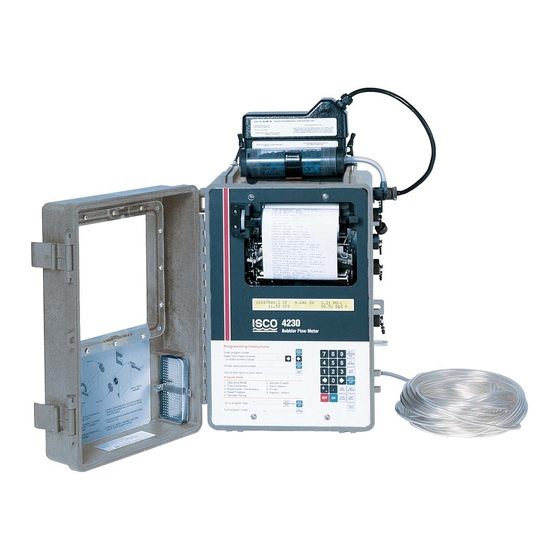
Section 4: Options and accessories for all 4200 series flow meters Section 5: Routine maintenance and minor service Following Section 5 are appendices covering safety, accessory parts, replacement parts, and material safety data. Figure 1-1 4230 Flow Meter, Shown With Bubble Line and Battery... -
Page 16: Description
The 4230 uses the bubbler method of level measurement. The flow meter is normally used with some type of primary mea- suring device to measure flow in an open channel. The 4230 has built-in standard level-to-flow conversions, that cover the vast majority of open channel flow measurement situations. -
Page 17: Operating Principles
1.3.1 Operation of the The bubbler system, used by the 4230 to sense level in the flow Bubbler System stream, works as follows: A small compressor pumps air into a reservoir. -
Page 18: Automatic Drift Compensation Valve
Refer to Figure 1-2 for a view of the controls, indicators, and con- nectors. 1.6 Technical The technical specifications for the 4230 Flow Meter are found in Specifications Table 1-2. The anticipated longevity for a roll of paper used in the printer is shown for various chart speeds in Table 1-4. - Page 19 4230 Flow Meter Section 1 Introduction Figure 1-2 4230 Controls and Indicators (left), Connectors (right) Table 1-1 4230 Controls, Indicators, and Connectors CONTROLS SETTINGS FUNCTION ON/OFF On - Off Turns the flow meter on and off. Internal memory is protected with a standby battery.
- Page 20 Connects flow meter to sampler; provides flow pulse to sampler; receives sampler bottle number, composite sample and event mark signal. Rain Gauge/ 9-pin female M/S Connects flow meter to an Isco Rain Gauge or YSI 600 Multi-Parameter YSI 600 Sonde. Also provides output to High-Low Alarm Relay Box. (Custom)
-
Page 21: Technical Specifications For Flowlink And Bubbler
4230 Flow Meter Section 1 Introduction Table 1-2 4230 Technical Specifications (Continued) Printer Recording Span User-selected from ft. (3.6 cm) to over 30 ft. (9.1 m) with multiple over-ranges of selected recording span Chart Resolution 0.001 ft. (0.3 mm) Display Resolution 4.5"... -
Page 22: Battery Life Expectancy
During data collection, if the measured level falls between two table values, the flow meter will perform a linear interpolation to calculate the flow rate value. Table 1-4 4230 Chart Longevity Chart Speed, Inch/Hour Time to Empty Roll... -
Page 23: How To Make Battery Calculations
4230 Flow Meter Section 1 Introduction Table 1-5 Battery Life Expectancy (Continued) Notes 1. These figures are approximations based on calculations; actual times for your flow meter may deviate due to factors of battery age, charge condition, operating temperatures, and component variations. -
Page 24: Calculating Current Draw
Always operate these batteries with a reserve factor. 1.7.1 Calculating Current Calculating current draw for a 4230 Flow Meter is somewhat Draw more difficult than calculating the battery capacity. You cannot simply measure the idle current of the unit unless the printer and report generator are turned off in the program. - Page 25 More information about batteries used to power Isco equipment is available from the Isco Power Products Guide, which is shipped with this manual and any flow meter order. 1-11...
- Page 26 4230 Flow Meter Section 1 Introduction 1-12...
-
Page 27: Section 2 Programming
4230 Flow Meter Section 2 Programming 2.1 Getting Started You must program the 4230 Flow Meter to accurately monitor a flow stream. The 4230 will usually also need a primary mea- suring device, a structure placed across a stream that regulates flow. -
Page 28: Keypad Functions
4230 Flow Meter Section 2 Programming (Programmed by condition means that the flow meter will enable the sampler only when a certain condition or set of conditions, sensed by the flow meter, are met.) Total Flow Current Level Date (or pH/D.O.) -
Page 29: Programming Procedure
Manual Purge – This key lets you purge the bubble line on the 4230 at any time. 2.4 Programming To begin programming the 4230, turn on the flow meter and wait for the display to settle. Then either press the Enter/Program Procedure Step key (generally referred to as Enter) or the Go To Program Step key. - Page 30 4230 Flow Meter Section 2 Programming be flashing. The flashing indicates that this choice is the current one held in memory. If you are satisfied with this choice, just press Enter, and the flow meter will advance to the next step.
-
Page 31: Description Of Program Steps
4230 Flow Meter Section 2 Programming a complete list of your program choices by exiting the program and by pressing the Print Program key as soon as the display returns to the normal operating condition, displaying level and total flow, etc. -
Page 32: Flow Conversion Type
2.5.2 Flow Conversion Type Step 2, Flow Conversion Type, determines how the flow meter calculates flow rate and total flow. For the 4230, flow rate is cal- culated by knowing the measured level and (usually) the charac- teristics of a structure called a primary measuring device. - Page 33 19th-century Irish civil engineer. There is no primary measuring device as such. Instead the pipe, with considerations for its slope and internal roughness, serves as the primary device. The 4230 Flow Meter can calculate flow in round pipes, rectangular, U-shaped, or trapezoidal channels based on this formula.
-
Page 34: Adjust Level, Parameters
Section 2 Programming outlet and have an opening in the face that is either round or tri- angular. The 4230 reads the upstream level (the water backs up behind the insert) and calculates the flow through the insert from this measured level. -
Page 35: Reset Totalizer
It is common to use a flow meter with an Isco sampler. Typically, the flow meter signals the sampler to take a sample after a certain volume has passed. -
Page 36: Sampler Enable
D.O., pH, and the YSI outputs. 2.5.7 Alarm Dialout Mode This feature allows you to program a 4230 to signal a remote location through a telephone line. This feature is useful for trans- mitting alarm conditions or other essential information to a remote location. -
Page 37: Printer
2.5.8 Printer The 4230 has a built-in printer. The printer is also capable of plotting linear data along with printing alphanumeric (letters and numbers) messages. In this step you set the speed for the chart to advance, from "... -
Page 38: Step 1 - Operating Mode
4230 Flow Meter Section 2 Programming Note Some items that appear in these menus will have parentheses (...) around them. This means that the item may or may not appear on your flow meter. Choices you make early in the pro- gram will make some options unavailable later. - Page 39 D.O., dissolved oxygen. Note If you are using the Isco D.O. sensor or are sensing D.O. with the YSI 600 Sonde, select as long a measurement interval as is practical for your application. The reasoning is that the D.O.
- Page 40 If your installation is AC-powered, you can simply select CONTINUOUS. • For the 4230, there is little difference in battery consumption between the choices. If you need a faster response time, select a shorter interval. If...
- Page 41 After selecting the appropriate parameter reading interval, press Enter. The Setup menu will reappear. This time select STATUS from the Setup menu. The following will appear: 4230 HW REV: XXXXXX SW REV X.XX ID XXXXXXXXXXX HW REV refers to the hardware revision number.
- Page 42 4230 Flow Meter Section 2 Programming The HYSTERESIS menu lets you set the range over which the level (or other condition) can vary before the flow meter responds to the change. In the PROGRAM section, there are several steps that require a change in a condition to make the flow meter carry out certain actions.
-
Page 43: Optional Outputs
10-50 mA (not supported by the flow meter). Isco offers two different arrangements for the 4-20 mA control circuit. You can have either or both with the same flow meter. - Page 44 16 mA whether activated or not. While 4-20 mA applications are generally made in installations with com- mercial power available, Isco suggests the following for those who have a 4-20 mA output in a battery-powered installation.
- Page 45 4230 Flow Meter Section 2 Programming CAUTION If you do not have the proper hardware installed and you press 4 - 2 - 0 and the number of analog outputs is not zero, the external 4-20 mA converter will not work properly. If this occurs return to the 4 - 2 - 0 option, and at the prompt, enter 0 for the number of outputs activated.
-
Page 46: Serial Output
Serial Output port. Special cables may be required. Contact Isco technical support for more information. Command Line: (Use the INTERROGATOR connector.) The lines of text contain the port values for each port that is turned on. - Page 47 4230 Flow Meter Section 2 Programming Table 2-1 ASCII Output Codes (Continued) Code Parameter Units Temperature Degrees Celsius YSI 600 pH pH units YSI Dissolved Oxygen Milligrams per liters YSI 600 Conductivity Millisiemens per centi- meter YSI 600 Specific Conduc-...
- Page 48 4230 Flow Meter Section 2 Programming with the appropriate ASCII output string. You can send the DATA command as often as you want. Type ‘Q’ to leave the command response interface. In addition to the port values, the data includes the flow meter’s current time, the bottle number and time stamp of the three most recent sample events, the previous day’s rainfall total (mid-...
- Page 49 OPTIONAL OUTPUTS menus have been set, press Enter. The display will return to the SETUP menu. The alarm box, also called the High-Low Alarm Box, is an Isco product that allows you to operate control relays to signal alarms when flow rate rises above or falls below a certain set value.
- Page 50 4230 Flow Meter Section 2 Programming Select YES if you want DO/PH to appear in the report. You must have the appropriate sensor connected to sense parameters; the flow meter is capable of sensing temperature, pH and temper- ature, and D.O. (dissolved oxygen) and temperature. The fol-...
- Page 51 4230 Flow Meter Section 2 Programming SET CLOCK, SITE ID, MEASUREMENT SETUP, PROGRAM LOCK, PROGRAM are off-screen and can be accessed with the arrow keys. Select LCD BACKLIGHT with the arrow key. The following will appear: LCD BACKLIGHT MODE • KEYPRESS TIMEOUT • • CONTINUOUS • • OFF •...
- Page 52 Further changes will require entry of the password, which is the number of the flow meter, 4230. If you select ON, there is a time-out before the lock engages. If you continue to work through the rest of the program, the lock will not engage until you are done.
- Page 53 RAIN GAUGE • INCHES • • MM • • NOT MEASURED • You must have an Isco 674 Rain Gauge connected to the flow meter through the Rain Gauge Port to sense rainfall. MM = milli- meters. The rain gauge is factory-calibrated. If you do not want to use a rain gauge, you would select NOT MEASURED for this step.
- Page 54 • pH • • NOT MEASURED • pH measurement determines the relative acidity or alkalinity of a solution. You must have an Isco pH Probe connected to the flow meter through the parameter port to sense pH. pH measure- ments range from 0 to 14 pH units, with solutions below 7 con- sidered acidic and solutions above 7, alkaline.
- Page 55 Note 4230 Flow meters with 4-pin Rain Gauge connectors cannot support the YSI 600. It is necessary to return the flow meter to the factory for modifications. There are also significant internal modifications to the flow meter’s electronics and software.
- Page 56 4230 Flow Meter Section 2 Programming Note The flow meter cannot communicate at 600 baud. If your sonde has been set up for 600 baud, you will get a communi- cations failure. Consult the YSI 600 Manual for what to do in this case.
-
Page 57: Step 2 - Flow Conversion
WEIR/FLUME, the following display will appear: TYPE OF DEVICE: • WEIR • • FLUME • For detailed information on weirs and flumes, refer to the Isco Flow Measurement Handbook that was shipped with your flow meter. Consulting the manufacturer of the specific weir or flume is also worthwhile. - Page 58 4230 Flow Meter Section 2 Programming If you select CIPOLLETTI, the following will appear: CIPOLLETTI WEIR ENTER CREST LENGTH XX.XXX FEET (or meters) If you selected FLUME for the type of standard device, the fol- lowing display will appear: SELECT TYPE OF FLUME •PARSHALL •...
- Page 59 4230 Flow Meter Section 2 Programming If you select HS for the type of flume, the following display will appear: HS FLUME SIZE • 0.4' • • 0.5' • • 0.6' • • 0.8' • • 1.0' • If you select H FLUME, the following will appear: H FLUME SIZE •...
- Page 60 For example: 0.01 -------- - Roughness coefficients are published in the Isco Open Channel Flow Measurement Handbook. You must know the material the pipe is made of. The roughness coefficients are published for all common materials in three grades: minimum, normal and maximum.
- Page 61 DATA POINT flow conversion allows you to enter measured level and flow rate values for a number of different points. The 4230 can accept as many as four sets of data points with each set con- taining up to fifty points.
-
Page 62: Flow Metering Inserts
ENTER: XX.XX (level units) XXX.XXX (volume) 2.8.1 Flow Metering Inserts There is one more possible flow conversion for the 4230 Bubbler Flow Meter. This option will appear as FLOW METERING INSERTS. These devices are metal inserts for 6", 8", 10", and 12"... -
Page 63: Enter Maximum Head
4230 Flow Meter Section 2 Programming The flow meter calculates flow based on this measured level. If you select METERING INSERTS for the FLOW CONVERSION mode, the following menu will appear: SELECT WEIR/ORIFICE TYPE • V-NOTCH • • ROUND •... - Page 64 4230 Flow Meter Section 2 Programming Note If you do not turn on the 4-20 mA output(s) in step 1, the menus determining its (their) operation will not appear later in the program. If you need this function and cannot find the...
-
Page 65: Step 3 - Parameter To Adjust
4230 Flow Meter Section 2 Programming 2.9 Step 3 - Parameter to This step lets you enter the measured level in the flow stream. It also lets you calibrate the pH (acidity or alkalinity), D.O. (dis- Adjust solved oxygen) parameter sensors, and the YSI 600 Multiple Parameter Sonde. - Page 66 4230 Flow Meter Section 2 Programming See Section 3, Installing the Level Sensor, for more information. Enter this value with the number keys. LEVEL ADJUST must be done at the job site, while most other programming can be done in the shop. Unless you have reliable information about the size of the channel, you should measure that, also.
- Page 67 4230 Flow Meter Section 2 Programming If you select D.O. for parameter to adjust, the following display will appear: DISSOLVED OXYGEN CALIBRATION •D.O. STANDARD••ABS BAROMETRIC PRESSURE•> ALTITUDE is just off screen to the right. If you select D.O. STANDARD for the calibration method, the following display will appear: D.O.
- Page 68 • D.O. STANDARD• •ABS BAROMETRIC PRESSURE •> ALTITUDE is just off screen to the right. Programming for YSI 600 D.O. is essentially the same as that described for the Isco D.O. sensor on the preceding section, with the exception that you always place the sensor in a cup, rather than wrap a moist cloth around it as is done for the Isco D.O.
- Page 69 4230 Flow Meter Section 2 Programming called the mho (ohm spelled backwards), and that term is more familiar to some. PPT is parts per thousand. Select the standard most suitable for your application. CONDUCTIVITY STANDARD X.XX MS/CM Then: PLACE PROBE IN X.XX MS/CM PRESS ENTER WHEN STABLE: X.XX MS/CM...
- Page 70 4230 Flow Meter Section 2 Programming Figure 2-4 YSI 600 Sonde Calibration Flow Chart 2-44...
-
Page 71: Step 4 - Reset Totalizer
T h e F L O W L I N K m e n u o p t i o n w i l l n o t a p p e a r u n l e s s FLOWLINK, Isco's proprietary data acquisition and storage software, is installed and pacing has been downloaded from FLOWLINK. - Page 72 4230 Flow Meter Section 2 Programming If FLOWLINK appears for sampler pacing, the operation of sampler pacing has been determined by choices made in FLOWLINK software. FLOWLINK controls the flow meter remotely, via phone lines and a modem, or locally with a laptop computer and cable.
- Page 73 4230 Flow Meter Section 2 Programming If you select GREATER THAN, the flow meter will ask you to enter a maximum value for the selected condition, which if exceeded, will trigger the flow pulse. If you select LESS THAN, the flow meter will ask you to enter a minimum value for the selected condition.
-
Page 74: Step 6 - Sampler Enable
LEVEL in the flow stream. Second, enter a value for RAINFALL. Third, enter an amount of time over which the rainfall occurs. Finally, you enter a time since the last rainfall. You must have an Isco Rain Gauge to measure rainfall. The following menus are the STORM sequence: LEVEL GREATER THAN X.XXX FT (Or other units, as selected.) - Page 75 4230 Flow Meter Section 2 Programming Then: RAINFALL TIME PERIOD • 15 MIN • • 30 MIN • • 1 HR • • 2 HR • • 4 HR • If you press the right arrow key several times, the following...
- Page 76 4230 Flow Meter Section 2 Programming If you select RATE OF CHANGE, the flow meter will ask you to enter two values, one for the condition, and the other for a period of time over which the change occurs. After you have determined what condition will signal the...
-
Page 77: Step 7 - Alarm Dialout Mode
4230 Flow Meter Section 2 Programming ENABLE CURRENTLY LATCHED, RESET • NO • • YES • Select YES to reset the sampler enable feature; select NO to leave the sampler enabled:. PRINTER ON/OFF WITH ENABLE • YES • • NO •... - Page 78 4230 Flow Meter Section 2 Programming If you press the right arrow key several times, the following times will appear: RAINFALL TIME PERIOD • 6 HR • • 8 HR • • 12 HR • • 24 HR • • 48 HR • • 72 HR •...
- Page 79 4230 Flow Meter Section 2 Programming If you want either of two conditions to trigger an alarm, select OR. If you want both of two conditions to be met before signalling an alarm, select AND. Selection of DONE will advance you to the next display menu.
-
Page 80: Step 8 - Printer
4230 Flow Meter Section 2 Programming 2.14 Step 8 - Printer This step sets up the operation of the flow meter's internal p r i n t e r. T h i s p r i n t e r a l s o f u n c t i o n s a s a p l o t t e r. T h e... - Page 81 PLOT RAINFALL ON CHART? • NO • • YES • You must have an Isco Rain Gauge connected to the flow meter to measure rainfall. Output is recorded in either inches or milli- meters. There is only one over-range for rainfall.
-
Page 82: Step 9 - Reports/History
4230 Flow Meter Section 2 Programming 2.15 Step 9 - This step lets you set up the flow meter to print periodic reports. The typical report contains such information as the period of Reports/History time covered in the report, maximum and minimum levels, and when they occurred. - Page 83 4230 Flow Meter Section 2 Programming DAYS or MONTHS could also appear depending on what you selected for the previous step. The time selected becomes the time interval that will be covered in the report. Then the flow meter will ask you when you want the first report printed:...
- Page 84 4230 Flow Meter Section 2 Programming Flow Meter History Contents D.O. ADJUSTED pH ADJUSTED LEVEL ADJUSTED FLOW CONVERSION CHANGED PLOTTER SPEED CHANGED PLOTTER TURNED ON PLOTTER TURNED OFF TIME CHANGE FROM TIME CHANGE TO REPORT A CHANGED REPORT B CHANGED...
-
Page 85: Section 3 Installation
Meter. There is also information on mounting methods, intercon- nection wiring, and the setup procedure. 3.1 Preparation for Use Isco ships the flow meter with a roll of paper installed and a default program entered into memory. You should familiarize yourself with the programming procedure and practice working through the program steps, so you become comfortable with pro- gramming the unit. -
Page 86: Opening The Case
3.2.2 Isco Sampler If you are using the 4230 Flow Meter with an Isco Sampler in a flow-paced sampling system, you can power the flow meter from the sampler's battery or power supply. Connect the flow meter to... -
Page 87: Isco Nickel-Cadmium Battery
Battery battery to power the flow meter. Isco packages this battery spe- cifically for use with Isco flow meters and samplers. Refer to the Power Products Guide accompanying this manual for detailed information about this battery and the procedure for charging it. -
Page 88: Isco Lead-Acid Battery
“sparking” the output (shorting the terminals together with a screwdriver or other tool). 3.2.5 AC Power Supplies Isco offers two different AC power supplies, the High Capacity Power Pack and the Battery-Backed Power Pack to power the flow meter. These power supplies are designed for operation on 120 VAC, 50/60 Hz commercial power sources. -
Page 89: External 12 Volt Direct Current Source
However, you will have to mount batteries of this type externally, as they are too large to fit on top of the flow meter. Isco offers a special optional connect cable to power the flow meter from a separate battery. -
Page 90: Purging A Clogged Bubble Line
" ID line. 3.3.3 Purging a Clogged When you use the 4230 to measure levels in small channels, it is Bubble Line best to keep the bubble rate at one-per-second and use shorter bubble lines. Larger-ID bubble lines are less likely to clog than small ones, but require more energy to supply the additional air needed. -
Page 91: Adjusting The Bubble Rate
4230 Flow Meter Section 3 Installation 3.3.4 Adjusting the Bubble Make the initial setting of the bubble rate at the shop, rather Rate than at the job site. At the shop you can put the bubble line in a container beside the flow meter and watch the rate while you adjust it. -
Page 92: Effects Of Changing The Bubble Rate
3.4 4230 Mounting and Because the 4230 Flow Meter is a portable device, it may or may Installation not be permanently installed. You can suspend the flow meter in... -
Page 93: Safety Considerations
WARNING The 4230 Flow Meter has not been approved for use in “hazardous locations” as defined by the National Electrical Code. Figure 3-2 4230 Suspended by Handle (handles may vary) -
Page 94: The Bubble Line
" inch (0.32 cm) ID, vinyl line, 50 feet long (15.2 m). You can specify either line at the time you order the unit. Isco ships the bubble line in the flow meter's accessory package, and Isco offers replacement lengths. -
Page 95: Teflon Line Connector
4230 Flow Meter Section 3 Installation should recognize that a larger bubble line will result in increased power consumption, a concern if you must power the flow meter by battery. You should keep the bubble rate at one to two bubbles per second, regardless of bubble line size. -
Page 96: Installing The Bubble Line
You do not need to locate the outlet of the bubble line precisely at the “zero” liquid level of the weir or flume. The Parameter to Adjust program step of the 4230 allows you to locate the outlet end of the bubble line anywhere within ten feet (3 m) above or below the actual zero level of the primary device. - Page 97 A. /” OD x / ” ID Teflon Bubble Line 1 16 Flow Meter Vinyl Bubble Case Line Tubing Barbed Fitting (With Silicone Tube Removed) B. /” OD x /” ID Teflon Bubble Line Figure 3-3 Attaching the Bubble Line to the 4230 3-13...
-
Page 98: High-Velocity Flow Streams
4230 Flow Meter Section 3 Installation Note The 4230 cannot accurately measure liquid levels that are even with or below the bubble line outlet. If you need to measure the liquid level down to the actual “zero” level of the primary device, Isco recommends placing the bubble line outlet at least 1 to 2 inches (2.5 to 5.1 cm) -
Page 99: Stilling Wells
For some applications, metallic bubble line extensions may be Extensions helpful. Isco offers both stainless steel and copper bubble line extensions. The stainless steel tube may be easier to install in the flow stream than the plastic bubble line because of its rel- ative rigidity. -
Page 100: Open Channel Installation
3.6 Flow Metering Inserts Flow metering inserts are available for use with the 4230 Flow Meter that you can temporarily install inside round pipe sewers and flow streams to create a primary device inside the pipe. - Page 101 A removable metal plate, formed with a V-notch opening, attaches to the upstream side of the insert. Each insert also contains a bubble line for a 4230. The rubber bladder, inflated by a removable, foot-powered pump, holds the insert securely in place after you install it inside the pipe.
-
Page 102: The Bubbler Tube Retainer Assembly
The following sections describe connecting the 4230 to Isco and non-Isco samplers. Sampler One of the uses of the 4230 Flow Meter is to control a sampler in a flow-paced sampling mode. Flow-paced sampling means that the flow meter signals the sampler to take a sample after a certain volume of flow has passed through the flow stream, rather than after a particular period of time. -
Page 103: Connection To Other Isco Equipment
A “new” cable will show continuity (zero ohms) between the two “F” pins; an old” cable will show open. 3.8.1 Connection to Other Isco manufactures a variety of useful accessories for use with the Isco Equipment 4230 Flow Meter. Among these options are: modems, parameter sensors, the alarm relay box, the rain gauge, a 4-20 mA output device, software, and a mechanical totalizer. - Page 104 4230 Flow Meter Section 3 Installation 3-20...
-
Page 105: Section 4 Optional Equipment
Section 4 Optional Equipment This section describes accessories and companion equipment available for use with the 4230 flow meter. There are two groups of equipment. One group can be used with any 4200 series flow meter. The other group is equipment for a specific type of level sensing and can only be used with the 4230 flow meter. -
Page 106: Modem And Flowlink Software
Disconnect the interroga- tor cable in order to use the 4200T Modem. 4.1.2 Modem and The 4200T Modem communicates with Isco's FLOWLINK data FLOWLINK Software storage and acquisition software, setting up the flow meter to collect blocks of data. -
Page 107: Types Of Service
“If trouble is experienced with this equipment, please con- tact the Isco Customer Service Depar tment, (800) 228-4373 or, outside the U.S.A., call (402) 464-0231, 4700 Superior St., Lincoln Nebraska, 68504-1398, for repair and (or) warranty information. -
Page 108: Connections To External Serial Device
If you are using the flow meter with an Isco sampler, the data line also includes an indication of a sampling event. -
Page 109: To 20 Ma (Analog) Outputs
4 mA becomes the 0% or baseline for the condition, while 20 mA becomes the 100% or full-scale of the condition. Isco offers two different arrangements for providing the 4-20 mA outputs. One is an external box that converts the signals from the flow meter to a 4-20 mA current loop. -
Page 110: Ma Output Interface
AWG wire. Figure 4-1 4-20 mA Output Interface 4.3.2 Internal Analog Output For those needing more than one analog output, Isco offers the Board Multiple Analog Output Board, which is installed inside the flow meter. This board provides from one to three isolated analog outputs. -
Page 111: Multiple Analog Output Board: Technical Specifications (Each Circuit)
• Use a Solar Panel Battery Charger • Use a larger battery: either a commercial deep-cycle/marine type, or an Isco 35 Ampere-hour lead-acid battery. • Order and use only one analog output. • Flow meter program choices also affect power consumption. -
Page 112: Tipping Bucket Rain Gauge
You may disregard these wires, as they are not connected in this application. 4.4 Tipping Bucket Rain A Tipping Bucket Rain Gauge is available from Isco for use with 4200 Series Flow Meters. The rain gauge connects to the flow Gauge meter by a cable terminated in an M/S connector. -
Page 113: Isco Flowlink Software
FLOWLINK Software is available from its manual or from the factory. 4.6 High-Low Alarm Relay Isco offers a control box that monitors flow rate data available from any 3000 or 4200 Series Flow Meter. Alarm relays trip when the flow rate exceeds or falls below pre-selected limits. -
Page 114: Installation
Flow Meter Meter requires a cable and an M/S connector. A special cable, 25 feet long, is available from Isco. On one end of the cable is a 4-pin, male M/S connector. Plug this connector into the Rain Gauge connector on the flow meter. The other end of the cable has three stripped wires. -
Page 115: Parameter Sensing
(if FLOWLINK software is used) storing data provided from parameter sensors. The parameter sensors that are available from Isco for use with 4200 Series Flow Meters are for temperature measurement, dissolved oxygen (D.O.) and pH (indicating the acidity or alkalinity of a solution), and the YSI 600 Multi-Parameter Sonde. -
Page 116: Temperature Probe
4230 Flow Meter Section 4 Optional Equipment Note The pH and D.O. probes require continuous submersion after installation, or they will lose sensitivity. Prolonged dehydra- tion of the sensor bulb may damage or even ruin the pH probe. 4.7.2 Temperature Probe The temperature probe is the simplest of the three, consisting of a thermistor inside a metal housing. -
Page 117: How The Ph Probe Works
Consequently, temperature compen- sation is provided in the flow meter. The Isco pH probe has a built-in temperature sensor that is exposed for faster response. 4-13... -
Page 118: Ph Probe Calibration
The potential, when read by a sensitive voltmeter, translates into a reading of pH. With an Isco flow meter, the voltage is sent first to a preamplifier inside the probe to reduce the impedance of the circuit and improve the signal-to-noise ratio, and then on to the 201 module to allow greater operating distance from the flow meter. -
Page 119: Ph Probe Installation Guidelines
Suspending the probe in the stream is not stable. For horizontal mounting, the probe fastens to a sensor carrier that snap-fits to an Isco mounting ring. The mounting rings fit various diameters of round pipes 15" diameter and smaller. For 4-15... - Page 120 4230 Flow Meter Section 4 Optional Equipment larger pipes, use the Isco Universal Mounting Ring. For instal- lation details, refer to the instruction sheet supplied with the mounting ring. The mounting rings are held in place by the outward force of spring pressure in the smaller sizes and by a screw arrangement in the larger sizes.
- Page 121 4230 Flow Meter Section 4 Optional Equipment but Isco recommends facing upstream, as there is a stop on the sensor carrier that is not effective when the probe is facing downstream. • Remember to unscrew the rubber guard cap from the sensing end of the probe when you install it, or the probe will be unable to sense the flow stream.
-
Page 122: Storage And Maintenance Of Ph Probes
4230 Flow Meter Section 4 Optional Equipment 4.8.4 Storage and If you remove the pH probe from operation, be careful to keep the Maintenance of pH glass sensor bulb wet. Always store the probe with the rubber Probes cover screwed completely over the threaded end of the sensor. -
Page 123: How The D.o. Probe Works
• Frequent maintenance is necessary when the probe is installed in flows with high grease or solids content. Tests conducted by Isco with probes installed in various waste streams have indicated that greases and solids quickly coat the probe's membrane, making it impos- sible for oxygen to enter the reaction chamber. -
Page 124: Probe Preparation
4230 Flow Meter Section 4 Optional Equipment As the oxygen partial pressure varies, both the oxygen diffusion through the membrane and the probe current change propor- tionally. 4.9.2 Probe Preparation The following describes how to prepare a new probe for use, or how to change membranes on an existing probe. -
Page 125: Membrane Thicknesses
4230 Flow Meter Section 4 Optional Equipment 4.9.3 Membrane Isco supplies a 2 mil (.002") thick membrane for use with the Thicknesses D.O. probe. This membrane is recommended for long-term moni- toring situations only, typical of our users' applications. Use only this thickness of membrane with D.O. - Page 126 (which can result from extended use with a loose or wrinkled membrane), you need to restore its surface. You can return it to Isco or clean it yourself with a probe reconditioning kit. (This kit is available from Isco.) Never use chemicals or any abrasive not supplied with this kit.
-
Page 127: Calibrating The D.o. Probe With A Flow Meter
4230 Flow Meter Section 4 Optional Equipment Figure 4-7 D.O. Parameter Module You must use the Isco Model 270 D.O. Module box between the probe and flow meter; this extends the distance between the probe and the flow meter to 1,000 feet.) 4.9.6 Calibrating the D.O. -
Page 128: Installation Of Parameter Probes In Round Pipes
4230 Flow Meter Section 4 Optional Equipment Altitude is just off the screen. You can select D.O. STANDARD if this calibration medium is available to you. Do not select ABS (absolute) BAROMETRIC PRESSURE unless you are at sea level or know how to correct for this value. The barometric pressure provided from the Weather Bureau is corrected for altitude. -
Page 129: Pipes Larger Than 15
Figure 4-8 Spring Ring (15” and Under) 4.10.2 Pipes Larger Than 15” For pipes 18 inches in diameter and larger, Isco offers the adjustable Universal Mounting Ring. This device consists of two or more metal strips that lock together with tabs to form a single assembly. -
Page 130: U-Channel Mounting
4230 Flow Meter Section 4 Optional Equipment There is a base section where the probes are mounted, two or more extension sections (usually), and a scissors section at the top that expands the entire assembly and tightens it inside the pipe. - Page 131 This device mounts Isco flow probes and parameter probes in closed cylindrical, process or sewer pipes. The assembled rings can fit pipe diam- eters from 18"...
-
Page 132: Universal Mounting Ring Parts
4230 Flow Meter Section 4 Optional Equipment 7.5" 20" Extension 1 30" 68-3000-038 (pair) 40" 47.1" Extension 2 68-3000-039 (pair) Extension 3 68-3000-040 (pair) Scissors Mechanism 60-3004-170 Extension 4 Standard Base 68-3000-041 Section (pair) 60-3004-169 The Following Table Indicates Recommended Part Configuration For Various Pipe Diameters. -
Page 133: Finishing The Installation
There are countersunk holes on the base section near the mounting tabs for the probes. These holes are for use with the Isco Probe Extension only. Do not attempt to use them to mount the probe carriers or the probes themselves. -
Page 134: Ysi 600 Multiple Parameter Sonde
4230 Flow Meter Section 4 Optional Equipment Mounting Ring Direction of Flow Probe Probe Extension Figure 4-11 Mounting of Probe Extension 4.11 YSI 600 Multiple The YSI 600 Sonde is a multi-purpose, water quality mea- surement and data collection system. It is intended for use in Parameter Sonde research, assessment, and regulatory compliance. -
Page 135: Ysi 600 Multiple Sensor Sonde
4230 Flow Meter Section 4 Optional Equipment Cover removed Temperature to show sensors. pH sensor pH reference Conductivity (Inside) D.O. sensor End view, facing sensors Figure 4-12 YSI 600 Multiple Sensor Sonde Information about programming the flow meter to use the YSI 600 is found in Section 2 of this manual. - Page 136 4230 Flow Meter Section 4 Optional Equipment Table 4-5 YSI 600 Technical Specifications (Continued) Temperature Sensor Type Thermistor Range –5° to +45° C Accuracy ± 0.4° C Resolution 0.1° C Dissolved Oxygen % Saturation Sensor Type Rapid Pulse - Polarographic...
-
Page 137: Mechanical Totalizer
4230 Flow Meter Section 4 Optional Equipment 4.12 Mechanical Totalizer A mechanical totalizer is available for the Model 4250 that con- sists of a seven-digit, non-resettable mechanical counter mounted in the front panel. It must be ordered with the flow meter. - Page 138 4230 Flow Meter Section 4 Optional Equipment 4-34...
-
Page 139: Section 5 Maintenance And Service
CMOS circuitry. Isco recommends that you become familiar with the maintenance procedures presented here. While the 4230 is ruggedly built to withstand severe field conditions, it will function best and remain most reliable if you follow these simple procedures. -
Page 140: Desiccators
5.2 Desiccators The 4230 has a reusable desiccant canister held by a steel clamp on the inside of the case lid. There is also a tubular desiccant car- tridge on the top of the case next to the connectors. The canister contains silica gel that adsorbs moisture trapped inside the flow meter's case when it is closed. -
Page 141: Regenerating The External Desiccant Cartridge
4230 Flow Meter Section 5 Maintenance and Service 5.2.2 Regenerating the Isco supplies two different chemicals in the cartridges. Before External Desiccant regenerating them, you must identify the chemical your unit Cartridge uses. Both chemicals are blue when active and pink or pale amber when saturated. -
Page 142: Bubble Line Maintenance
5.3 Bubble Line Periodically inspect the bubble line from the 4230 to make sure Maintenance that it has not become kinked, frayed, cut, nicked, or damaged in any other way. If you find damage to the bubble line, replace it. A leaking or obstructed line will cause inaccurate level readings and lower battery life. -
Page 143: Automatic Air Purge
Section 5 Maintenance and Service 5.3.2 Automatic Air Purge The 4230 has an automatic purge feature to clear deposits from the bubble line with a sharp burst of air from the pump. Purge is intended to help keep the outlet of the bubble line open. The program substep PURGE INTERVAL (in Setup) allows you to set the time between purge cycles, from five minutes to one hour. - Page 144 4230 Flow Meter Section 5 Maintenance and Service 3. Remove the paper roll from the take-up spool by holding the handle in one hand with your thumb pressed against one of the slots in the white end cap. 4. Snap the white end cap free from the two black catches on the end of the spool.
-
Page 145: Ink Ribbon Replacement
4230 Flow Meter Section 5 Maintenance and Service 6. Be careful to push it all the way back in, so that the take-up gear on the end of the spool assembly will reen- gage. 7. When the take-up spool is back in place, again push the Paper Reroll key;... -
Page 146: Do Not Lubricate Or Disassemble
Isco recommends you make no attempt to oil or disassemble the mechanism if it malfunctions. Oil attracts dirt; some oils can become gummy over time and may cause parts to bind or stick. -
Page 147: Fuse Replacement
4230 Flow Meter Section 5 Maintenance and Service Figure 5-4 Lifting the Flow Meter from the Case Note If you disassemble the flow meter for servicing, you will also remove the aluminum chassis covers to access the circuitry. Always replace these covers when repairs have been com- pleted. -
Page 148: Display Warnings
Pressing 4 and Exit Program only works when the unit is pow- ering up; it has no effect when the unit is running. Note Pressing 4 and Exit Program when powering up will cause most programmed entries to be lost. Accumulated data stored in the 4230 will also be lost. 5-10... -
Page 149: Operation Of The Bubbler System
(800) 775-2695 or (402) 464-0231. CAUTION Do not attempt to disassemble or repair the 4230 Flow Meter (other than changing fuses) unless you are skilled in the evalu- ation and repair of microprocessor-based circuitry. Isco recom- mends no attempt be made to disassemble or repair the printer mechanism or display module. -
Page 150: Air Output To Bubble Line
4230 Flow Meter Section 5 Maintenance and Service Figure 5-6 4230 Bubbler System Pressure Control A fixed set-point pressure switch monitors air pressure in the tank. The reference side of this differential pressure switch con- nects to the bubble line. When the pressure in the tank falls below 3.5 psig above the water pressure being measured, the... -
Page 151: Pressure Transducer
4230 Flow Meter Section 5 Maintenance and Service AIR PUMP HYDROPHOBIC FILTER CHECK VALVE PRESSURE TRANSDUCER PRESSURE SENSOR BUBBLE RATE ADJUST VALVE BUBBLE LINE PURGE/SUPER AUTOMATIC DRIFT AIR TANK BUBBLE VALVE COMPENSATION VALVE Figure 5-7 Schematic Diagram of the Bubbler System... -
Page 152: Preliminary Troubleshooting Steps
Isco Technical Repair Department. (800) 775-2965 or (402) 464-0231 outside the U.S.A. The service department will advise you on how to return the 4230 to the factory for servicing. The Technical Repair Department has trained technicians and specially-designed equipment necessary for timely, efficient repair of the 4230 Flow Meter. -
Page 153: Precautions For Servicing Cmos Circuitry
11. Check the reset circuitry to see that it is working properly. 5.9 Precautions for Most of the circuitry in the 4230 Flow Meter is made up of CMOS components. Because of the oxide gate structure of these devices, Servicing CMOS... - Page 154 4230 Flow Meter Section 5 Maintenance and Service • Never perform any work in a room with a carpeted floor. • Always roll up your sleeves so that your arms are in contact with the working surface. • Avoid using a work surface made of an extremely good insulator.
-
Page 155: Using Flash Update
FLASH EPROM lets you upgrade the software in the instrument without opening the unit or returning it to the factory. You can now update the software with a disk from Isco, an IBM®-compatible personal computer and a connect cable. -
Page 156: Running Flash Update
4230 Flow Meter Section 5 Maintenance and Service • The instructions in the following section, Running FLASH UPDATE, assume you are running the program from the update disk. However, you may prefer to copy the disk’s contents to your hard disk. Before copying the disk, create a new directory for the FLASH UPDATE program and the update files. -
Page 157: Options Menu
The numbers following the “V” are the software version. If several versions appear in the window, select the version with the highest number unless otherwise instructed by Isco Technical Service. Figure 5-8 Update File Menu Options Menu... - Page 158 (Must operate at 19,200 baud when communi- cating through the serial port.) 640 kilobytes RAM (Random Access Memory), minimum Serial port For connecting the computer to Isco flow meters, flow loggers, or samplers. Keyboard Any compatible keyboard Hard disk Not required.
-
Page 159: Appendix A Accessories And Replacement Parts
4230 Flow Meter Appendix A Accessories and Replacement Parts A.1 Replacement Parts The following section contains illustrations and corresponding tables of 4230 Flow Meter replacement parts. A list of accessories and optional equipment can be found at the end of this section. - Page 160 4230 Flow Meter Appendix A Accessories and Replacement Parts...
- Page 161 4230 Flow Meter Appendix A Accessories and Replacement Parts...
- Page 162 4230 Flow Meter Appendix A Accessories and Replacement Parts...
- Page 163 4230 Flow Meter Appendix A Accessories and Replacement Parts Table A-1 4230 Replacement Parts List Part Number Complete Parts Description 60-3214-139 Motor Assy Chart Drive 4200 60-3214-093 LCD Module Assy B/L 60-3234-067 Case Bottom Sub Assembly 60-3214-098 PCB Assembly Keyboard...
- Page 164 Scr SS SST PH P 10-32 × ” 60-1704-017 Carrying Handle Assy 099-0012-00 Dri-Can Desiccant Canister * Not Shown Table A-2 4230 Pump Base Assembly Replacement Parts Part Number Complete Parts Description 60-3234-060 PCB Assy 4230 Sensor 209-0093-03 Hydrophobic Filter - Unidirectional...
-
Page 165: Accessories
Stainless Steel Bubble Tube ....................60-1873-043 Model 4230 Flow Meter......................60-3234-048 Model 4230 Flow Meter Only....................60-3234-049 4230 Accessories Model 4230 Flow Meter Instruction Manual ................60-3234-051 Model 4230 Flow Meter Pocket Guide..................60-3233-102 " ID × 25’ Teflon..................... 60-1873-051 Bubble Line, "... - Page 166 O-Ring Kit for D. O. Probe ....................... 479-0020-00 Temperature Probe only......................60-3214-130 Isco Sampler to Flow Meter Connect Cable - 25 ft..............60-3004-107 External 12VDC Source Connect Cable- 6 ft................60-1394-023 YSI 600 Sonde with pH, D.O., conductivity, temperature sensors, and 25 ft. cable ..... 68-0600-111 Note: Item 68-0600-111 includes a YSI-to-Isco 4200/6700 adapter cable, calibration/transport cup, 1# stainless steel nose weight, and YSI instruction manual.
-
Page 167: Universal Mounting Ring
YSI 600 and Isco 674 Rain Gauge Y-Connect Cable............... 60-0604-002 (This cable allows use of the YSI 600 Sonde and the Isco 674 Rain Gauge at the same time.) Use the following with Isco Mounting Rings in Round Pipe Installations Probe Carrier for Temperature probe .................. - Page 168 4230 Flow Meter Appendix A Accessories and Replacement Parts A-10...
-
Page 169: Appendix B Programming Worksheets
Appendix B Programming Worksheets Use this form to make a hard copy of the program you use in your 4230. Most program steps can be completed in the shop without the flow meter being installed or at the job site. However, please note the following: •... - Page 170 4230 Flow Meter Appendix B Programming Worksheets 8. D.O./ph Reading Interval: Continuous, 15 Sec, 30 Sec, 1Min, 2 Min, 5 Min 9. YSI 600 Reading Interval: Continuous, 15 Sec, 30 Sec, 1Min, 2 Min, 5 Min 10. Level Enable/Alarm: Hysteresis ________Feet (Or Meters) 11.
-
Page 171: Flow Conversion: Level-To-Flow Rate
4230 Flow Meter Appendix B Programming Worksheets 43. Flow Rate Units of Measure: GPS, GPM, GPH, MGD, CFS, CFM, CFH, CFD, LPS, M3S, M3M, M3H, M3D, AFD 44. Totalized Volume Units: GAL, MGAL, CF, L, M3, AF 45. Rain Gauge: Inches, MM, Not Measured 46. -
Page 172: Flow Metering Insert
4230 Flow Meter Appendix B Programming Worksheets 20. Mann. U-channel: Slope = __.____Rough = __.____ 21. Mann. U-channel: Width = __.____ Feet (or meters) 22. Mann. Rectangular: Slope = __.____ Rough = __.____ 23. Mann. Rectangular: Width = __.____ Feet (or meters) 24. -
Page 173: Parameter To Adjust
Note: Installations generally use either the Isco parameter probes or the YSI 600 Sonde, but not both. Use the follow- ing menus for either the Isco probes or the YSI 600 Sonde. Steps 3, 4, and 5 can be used for both 2 and 3-point pH cal- ibrations. -
Page 174: Alarm Dialout Mode
4230 Flow Meter Appendix B Programming Worksheets 4. Rainfall Time Period: 15 Min, 30 Min, 1 Hr, 2 Hr, 4 Hr, 6 Hr, 8 Hr, 12 Hr, 24 Hr, 48 Hr, 72 Hr 5. Time Since Last Rainfall: Days: ______ (enter 1 to 7) 6. -
Page 175: Reports/History
4230 Flow Meter Appendix B Programming Worksheets 6. Input For Printer Line C: None, Level, Flow Rate, pH, D.O., Temp, YSI pH, YSI D.O., YSI Cond., YSI Temp. 7. Plot Rainfall On Chart?: No, Yes B.9 Reports/History 1. Report Generator A: On, Off, (Print) 2. - Page 176 4230 Flow Meter Appendix B Programming Worksheets Additional table for Data Point Entry Data Point Set #2. Level Flow Level Flow Level Flow Level Flow...
-
Page 177: Appendix C General Safety Procedures
Appendix C General Safety Procedures 4230 Flow Meter Appendix C General Safety Procedures In field installations of 4230 Flow Meters and associated equipment, the safety of the personnel involved should be the foremost consideration. The following sections provide safety pro- cedures for working in and around manholes and sewers. - Page 178 4230 Flow Meter Appendix C General Safety Procedures “Sharp Edges. Sharp edges of items in or near a manhole may cause cuts or bruises. “Lifting Injuries. Unless proper tools are used to remove manhole covers, back injuries or injuries to hands or feet may result.
- Page 179 4230 Flow Meter Appendix C General Safety Procedures also function as guards to keep people and vehicles away from the manhole opening. To avoid a serious injury, a person should not be lifted out of a manhole by his arm unless it is a dire emer- gency.
-
Page 180: Lethal Atmospheres In Sewers
4230 Flow Meter Appendix C General Safety Procedures “10. Field Equipment. The following equipment will be available for use: Blowers Gloves Traffic cones Breathing apparatus Hard Hats Coveralls Harnesses First aid kits Manhole irons Emergency flashers Pick axes Flashlights Rain slickers... - Page 181 4230 Flow Meter Appendix C General Safety Procedures “It seems unlikely that anyone has ever died in a sewer from suf- focation, that is, a lack of oxygen. Deaths have often been attributed to ‘asphyxiation.’ This is a word which, according to the dictionary, is used to mean death from an atmosphere that does not support life.
-
Page 182: Hazardous Gases
4230 Flow Meter Appendix C General Safety Procedures number of harmful vapors. They, too, are sensed by smell and explosimeter tests if they get into the public sewer. Such occur- rences are rare. “The attempt to instill a sense of urgency about real hazards is diluted if a man is told to give attention to a long list of things that in fact are irrelevant. - Page 183 4230 Flow Meter Appendix C General Safety Procedures Table C-1 Hazardous Gases (Continued) Specific Explosive Likely Max. Safe Simplest and Gravity Range (% by Location Most Chemical Common Physiological Safe 60 8 Hour Cheapest or Vapor vol. in air) Common...
- Page 184 4230 Flow Meter Appendix C General Safety Procedures Table C-1 Hazardous Gases (Continued) Specific Explosive Likely Max. Safe Simplest and Gravity Range (% by Location Most Chemical Common Physiological Safe 60 8 Hour Cheapest or Vapor vol. in air) Common...
- Page 185 4230 Flow Meter Appendix C General Safety Procedures Table C-1 Hazardous Gases (Continued) Specific Explosive Likely Max. Safe Simplest and Gravity Range (% by Location Most Chemical Common Physiological Safe 60 8 Hour Cheapest or Vapor vol. in air) Common...
- Page 186 4230 Flow Meter Appendix C General Safety Procedures C-10...
-
Page 187: Appendix D Material Safety Data Sheets
This appendix provides Material Safety Data Sheets for the des- iccant used by the 4230 Flow Meter. Isco cannot guarantee the accuracy of the data. Specific ques- tions regarding the use and handling of the products should be directed to the manufacturer listed on the MSDS. - Page 188 4230 Flow Meter Appendix D Material Safety Data Sheets Indicating Silica Gel Material Safety Data Sheet Identity (Trade Name as Used on Label) Manufacturer MULTISORB TECHNOLOGIES, INC. MSDS Number* : (formerly Multiform Desiccants, Inc.) Address: CAS Number* : 325 Harlem Road...
- Page 189 4230 Flow Meter Appendix D Material Safety Data Sheets Page 2 Section 5 - Health Hazard Data PRIMARY ROUTES Inhalation Ingestion CARCINOGEN OSHA OF ENTRY Skin Absorption Not Hazardous LISTED IN IARC Monograph Not Listed HEALTH HAZARDS Acute May cause eye, skin and mucous membrane irritation.
- Page 190 4230 Flow Meter Appendix D Material Safety Data Sheets 101 Christine Drive Belen, New Mexico 87002 Phone: (505) 864-6691 Fax: (505) 861-2355 ISO 9002 MATERIAL SAFETY DATA SHEET -- September 28, 1998 ® SORB-IT Packaged Desiccant SECTION I -- PRODUCT IDENTIFICATION...
- Page 191 4230 Flow Meter Appendix D Material Safety Data Sheets 101 Christine Drive Belen, New Mexico 87002 Phone: (505) 864-6691 Fax: (505) 861-2355 ISO 9002 MATERIAL SAFETY DATA SHEET -- September 28, 1998 ® SORB-IT Packaged Desiccant SECTION IV -- FIRE EXPLOSION DATA Fire and Explosion Hazard - Negligible fire and explosion hazard when exposed to heat or flame by reaction with incompatible substances.
- Page 192 4230 Flow Meter Appendix D Material Safety Data Sheets 101 Christine Drive Belen, New Mexico 87002 Phone: (505) 864-6691 Fax: (505) 861-2355 ISO 9002 MATERIAL SAFETY DATA SHEET -- September 28, 1998 ® SORB-IT Packaged Desiccant NOTE TO PHYSICIAN: This product is a desiccant and generates heat as it adsorbs water.
- Page 193 4230 Flow Meter Appendix D Material Safety Data Sheets 101 Christine Drive Belen, New Mexico 87002 Phone: (505) 864-6691 Fax: (505) 861-2355 ISO 9002 MATERIAL SAFETY DATA SHEET -- September 28, 1998 ® SORB-IT Packaged Desiccant SECTION IX -- SPECIAL PRECAUTIONS Avoid breathing dust and prolonged contact with skin.
- Page 194 4230 Flow Meter Appendix D Material Safety Data Sheets...
- Page 195 4230 Flow Meter Index Numerics 4 to 20 mA Output Interface, 4-5 Hysteresis, 2-16 4-20 mA Output, 2-17, 2-37, 4-5 Installation Accessories List, A-7 Bubble Line, 3-12 Alarm Box, 4-9 Flow Meter, 3-8 Analog Output, 2-17, 2-37, 4-5 Safety Considerations, 3-9...
- Page 196 4230 Flow Meter Index Optional Outputs Analog, 2-17, 2-37, 4-5 Technical Specifications, 1-4 Serial, 2-20, 4-4 Tipping Bucket Rain Gauge, 4-8 Troubleshooting Steps, 5-14 Parameter Sensing, 4-11 Part Numbers (Replacement Parts), A-5 YSI 600 Sonde, 4-30 Power Consumption, 1-8, 1-9...
- Page 197 USA Representative European Authorized Representative Bill Foster Contact: Dr. Dirk Köppenkastrop Director of Engineering Geschäftsführer Managing Director Isco, Inc. STIP ISCO GmbH 4700 Superior Street Lincoln, Nebraska 68504 Siemensstraße 2 64823 Groß-Umstadt Phone: (402) 464-0231 Fax: (402) 464-4543 Telefon: 06078 7 86-82...
- Page 198 Mailing Address: P.O. Box 82531, Lincoln, NE 68501 Equipment Type/Environment: Laboratory Equipment for Light Industrial/Commercial Environments Trade Name/Model No: Model 4230 Bubbler Flow Meter Year of Issue: 2000 Standards to which Conformity is Declared: EN 50082-1 Generic Immunity for Commercial, Light Industrial...
- Page 199 Isco assumes no liability for any consequential damages. * This warranty applies to USA customers. Customers in other countries should contact their Isco dealer for warranty service. In the event of instrument problems, always contact the Isco Service Department, as problems can often be diagnosed and corrected without requiring an on-site visit.
Need help?
Do you have a question about the 4230 and is the answer not in the manual?
Questions and answers