
Related Manuals for Secced SC-Video-10/100VP

Summary of Contents for Secced SC-Video-10/100VP
- Page 1 Operators Guide Professional Fluid Head & Tripod Ares 3 system www.secced.com SC-Video-10/100VP SC-ENG/CF 100M Read this first before using and save it...
- Page 2 Beijing Secnovo Co., Ltd Secced is registered trademark of Beijing Secnovo Co., Ltd Printed in People Republic of China by Secnovo, Beijing.
-
Page 3: Technical Data
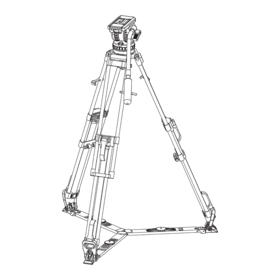
Beijing Secnovo Co., Ltd or your local distributor. For full details on maintenance and spare parts, please refer to the Ares 3 system Maintenance Manual and Illustrated Parts List. This is obtainable from Beijing Secnovo Co., Ltd or your local distributor. www.secced.com... - Page 4 Introduction The Ares 3 system include SC-Video-10/100VP fluid head, SC-ENG/CF 100M tripod,floor spreader and padded bag. The SC-Video-10 /100VP embodies 5 steps counterbalancing mechanism and the adjustable drag aseemblies for pan and tilt motions. The balance system is easily adjusted by a knob on the right-hand side of the head. The drag system ensures smooth movement of the camera about pan and tilt axes and are fitting with control knobs to adjust the drag setting.
-
Page 5: Table Of Contents
Fluid Head SC-Video 10/100VP Contents Operation ……………………………………………… Page 6 Installing the head on a tripod ……………………………………………… Page 6 Opening the pan bar ………………………………………………………… Page 7 Mounting the camera ……………………………………………………… Page 9 Balancing the head ………………………………………………………… Page 11 Pan and tilt brakes ………………………………………………………… Page 13 Pan and tilt drag …………………………………………………………... - Page 6 Fig 1 SC-Video 10/100VP (Left-Hand Side) Slide plate clamp Tilt drag adjustment knob Pan drag adjusment knob Bowl clamp Pan bar mounting Tilt brake knob Pan brake knob Head bowl...
- Page 7 Fig 2 (12) (13) (14) (10) (11) SC-Video 10/100VP (Right-Hand Side) Quick release knob (10) Balance knob (11) Level bubble (12) Quicklock wedge (13) Pan bar clamping sleeve (14) Pan bar clamping lever...
-
Page 8: Operation
Operation Installing the head on a tripod The Ares 3 fluid head is supplied with an integral 100mm ball mount, designed for installation on a compatible Secnovo tripod. To install the head, remove the bowl clamp (4) from the head (turn bowl clamp anti-clockwise as in Figure 3), position the head on the tripod and refit the bowl clamp from below. -
Page 9: Opening The Pan Bar
Opening the pan bar Open the black clamping lever (14) of the pan bar and move the pan bar into the desired position. Apply the clamping lever of the pan bar. During transportation the pan bar can be moved next to the tripod legs. - Page 10 Use of the enclosed pan bar on the left side of the fluid head is also possible. For this, it is advisable to relocate the clamp on the pan bar. The pan bar has to be removed from the head and the black plastic cap (16) on its top should be opened and removed with a coin or screwdriver.
-
Page 11: Mounting The Camera
Mounting the camera Tighten the tilt brake before mounting the camera Free the Quicklock wedge (12) from slide plate (17) by pulling the locking button down (9.2) and then operating the wedge-releasing lever (9.1) to another end. Fit the wedge either to the camera or the camera adaptor with two screws provided. If using the camera adaptor, just mount the camera on the camera adaptor after the wedge is attached with the camera adaptor. - Page 12 Insert the wedge into the camera plate until an audible click indicates that the Quicklock wedge is locked in position. WARNING! When mounting the camera/placing the wedge, make sure not to hold fingers within the range of the locking lever (9.1) and camera plate receptacle, since the lever may snap back.
-
Page 13: Balancing The Head
Balancing the head Balancing the head achieves two objectives. Firstly, when the head is correctly balanced the operator will need a minimum amount of effort to move the head. Secondly, once balanced, the head and its payload can be set to any tilt position and the head will maintain this position with ‘hand off’. - Page 14 Fig 8 continued III. Position 0 Release slide plate clamp Tighten slide plate clamp...
-
Page 15: Pan And Tilt Brakes
Pan and tilt brakes Friction brakes (6,7) on each axis allow the head to be locked at any chosen position. To apply the brake, turn the lever fully clockwise. To release the brake, turn the lever counter-clockwise. WARNING! When the brakes are not in use, make sure the brakes is at the released status. DO NOT use the brakes to supplement drag. -
Page 16: Servicing
Servicing Routine maintenance During use, check the following Check the condition of the clamping washer (15) and the pan bar clamping sleeve (13), replace them if the teeth of the clamping washer and clamping sleeve are almost weared away. Check the effectiveness of the slide plate, add some grease lubricant onto the slide plate if slide plate do not move when tilting to +45°... - Page 17 Tripod Contents Operation …………………………………………… Page 17 Servicing ……………………………………………… Page 19 Cleaning ………………………………………………………………… Page 19 Routine maintenance ……………………………………………………… Page 19 Adjusting the leg clamps …………………………………………………… Page 19...
- Page 18 Fig 11 (18) (22) (23) (19) (20) (24) (21) SC-ENG/CF 100M Tripod (18) Tripod bowl (19) Top clamp assembly (20) Bottom clamp assembly (21) Floor spreader (22) Locking clip (23) Mid-level spreader attachment assembly (24) Clamping knob...
- Page 19 Operation Lift the complete tripod and head out of the case and keep the floor spreader (21) attached to the tripod. Release the three locking clips (22), open out the legs while holding the legs. Gentle foot or hand pressure on the spreader will ensure that the legs are fully spread. NOTE: Always use the spreader where possible as this increases rigidity of the tripod.
- Page 20 Adjust the operating height by undoing the leg clamps (19.1, 20.1) and pulling the tripod up to the desired height. Adjust the spreader if necessary. Level the head with aid of the level bubble. Apply the clamps (19.1, 20.1) to lock the tripod. Fig 13 Pull up (19.1)
-
Page 21: Adjusting The Leg Clamps
Servicing Cleaning During indoor use the only cleaning required should be a regular wipe over with a lint-free cloth. Dirt accumulated during storage may be removed using a semi-stiff brush. Particular attention should be given to the mounting bowl of tripod. Use out-of-doors under adverse condition will require special attention. - Page 22 Fig 14 (19.2) (19.3) (19.1) (3) Tighten the screw with a hexagon bow wrench (Clcokwise) (2) Press the leg lock board down (1) Lift the top clamp up Top clamp Adjust a top clamp as follows: Lift the clamping lever (19.1) up. Press down the top leg lock board (19.2), use either suitable spanner or hexagon box wrench to tighten the screw (19.3) (as shown in Fig 14).
- Page 23 Fig 15 (20.1) (20.2) (1) Press the bottom clamp down (2) Tighten 4 screws with a hexagon bow wrench (Clcokwise) Bottom clamp Adjust a bottom clamp as follows: Press the bottom clamp down (20.1) and use the suitable box wrench to tighen the screw (20.2) as shown in Fig 15.
-
Page 24: Floor Spreader
Floor Spreader SC-FS100 Contents Operation …………………………………………… Page 24 Installing the floor spreader ……………………………………………… Page 24 Adjusting the spreader………………………………………………………Page 25... - Page 25 Fig 16 (25) (27) (28) (29) (26) (30) (31) SC-FS100 Floor Spreader (25) Foot retaining strap (26) Clamping knob (27) Inner leg (28) Outer leg (29) Lift ring (30) Core connecting assembly (31) Foot support...
- Page 26 Operation Installing the floor spreader To install a floor spreader onto a tripod proceed as follows: Unfold legs of spreader and place flat on the ground. Ensure three clamping knobs (26) are engaged. Lower tripod onto the spreader and locate the spike (32) onto the three foot supports (31). Secure tripod onto spreader by engaging three foot retaining straps (25) to each foot of the spreader.
- Page 27 Adjusting the spreader NOTE: Always use the spreader where possible as this increases rigidity of the tripod. At the full extension of the spreader and with all legs fully retracted, the tripod can be used at its lowest operating height. Although tripods can be set lower than this without spreader, it is NOT recommended as the tripod geometry become unstable.
- Page 28 Mid-Level Spreader SC-MS100 Contents Operation …………………………………………… Page 28 Installing the mid-level spreader ………………………………………… Page 28 Adjusting the spreader………………………………………………………Page 29...
- Page 29 Fig 19 (33) (36) (34) (35) (37) (38) SC-MS100 Mid-level Spreader (33) Spread-locking knob (34) Extension release knob (35) Attachment head (36) Outer arm (37) Inner arm (38) Attachment assembly...
- Page 30 Operation Installing the mid-level spreader The spreader may be installed on any tripod provided with attachment points. To install the spreader Grip the ends of each arm in turn and press in the attachment release buttons (38.1) on the tripod. Push the arm into the tripod attachment point (38.2) until the arm engages.
- Page 31 Adjusting the spreader There are two controls on the spreader. Spread-locking knob (33) and extension release knob (34) Spread-locking knob locks the mid-level spreader in position. With the particular length of arm, by turning the spread-locking knob, the height of the spreader can be adjusted The spreading scope of tripod can be adjusted by turning the spread-locking knob.
-
Page 32: Parts List
The following lists include main assemblies, user-replaceable spare parts and optional accessories. For further information regarding repair or spare parts, please contact Beijing Secnovo Co., Ltd or your local distributor. For information on-line,visit our website at www.secced.com Main assemblies Ares 3 Fluid head SC-Video 10/100VP... - Page 33 Beijing Secnovo Co., Ltd Printed in China...
Need help?
Do you have a question about the SC-Video-10/100VP and is the answer not in the manual?
Questions and answers