Sony XR-CA600 Service Manual
Fm/mw/lw cassette
Hide thumbs
Also See for XR-CA600:
- Operating instructions manual (172 pages) ,
- Operating instrutions (144 pages) ,
- Operating instructions manual (146 pages)
Table of Contents
Advertisement
Quick Links
XR-CA600/CA600V/CA600X
SERVICE MANUAL
Ver 1.1 2001.05
Cassette Player section
Tape track
Wow and flutter
Frequency response
Signal-to-noise ratio
Tuner section
FM
Tuning range
Aerial terminal
Intermediate frequency
Usable sensitivity
Selectivity
Signal-to-noise ratio
Harmonic distortion at 1 kHz
Separation
Frequency response
MW/LW
Tuning range
Aerial terminal
Intermediate frequency
Sensitivity
Power amplifier section
Outputs
Speaker impedance
Maximum power output
Sony Corporation
9-870-246-12
2001E0500-1
e Vehicle Company
C 2001.5
Shinagawa Tec Service Manual Production Group
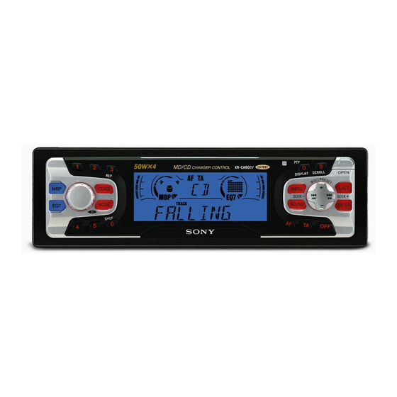
Photo: XR-CA600X
SPECIFICATIONS
4-track 2-channel stereo
0.08 % (WRMS)
30 – 18,000 Hz
Cassette type
TYPE II, IV
61 dB
58 dB
TYPE I
87.5 – 108.0 MHz
External aerial connector
10.7 MHz/450 kHz
8 dBf
75 dB at 400 kHz
66 dB (stereo),
72 dB (mono)
0.6 % (stereo),
0.3 % (mono)
35 dB at 1 kHz
30 – 15,000 Hz
MW: 531 – 1,602 kHz
LW: 153 – 279 kHz
External aerial connector
10.7 MHz/450 kHz
MW: 30 µV
LW: 40 µV
Speaker outputs
(sure seal connectors)
4 – 8 ohms
50 W × 4 (at 4 ohms)
Model Name Using Similar Mechanism
Tape Transport Mechanism Type
General
Outputs
Audio outputs (Rear)
Power aerial relay control
lead
Power amplifier control lead
Inputs
Telephone ATT control lead
BUS control input
connector
BUS audio input connector
Remote controller input
connector
Aerial input connector
Bass ±8 dB at 100 Hz
Tone controls
Treble ±8 dB at 10 kHz
Loudness
100 Hz +8 dB
10 kHz +2 dB
Power requirements
12 V DC car battery
(negative earth)
Approx. 178 × 50 × 176
Dimensions
mm (w/h/d)
Approx. 182 × 53 × 161
Mounting dimensions
mm (w/h/d)
Mass
Approx. 1.2 kg
Supplied accessories
Parts for installation and
connections (1 set)
Front panel case (1)
Note
This unit cannot be connected to a digital preamplifier
or an equalizer.
Design and specifications are subject to change
without notice.
FM/MW/LW CASSETTE CAR STEREO
AEP Model
UK Model
XR-C5300R
MG-25G-136
Advertisement
Table of Contents

Related Manuals for Sony XR-CA600


Summary of Contents for Sony XR-CA600
- Page 1 XR-CA600/CA600V/CA600X SERVICE MANUAL AEP Model UK Model Ver 1.1 2001.05 Photo: XR-CA600X Model Name Using Similar Mechanism XR-C5300R Tape Transport Mechanism Type MG-25G-136 SPECIFICATIONS General Cassette Player section Outputs Audio outputs (Rear) Tape track 4-track 2-channel stereo Power aerial relay control Wow and flutter 0.08 % (WRMS)
-
Page 2: Table Of Contents
6-6. Printed Wiring Board – SUB Board – ......19 6-7. Schematic Diagram – SUB Board – ....... 19 6-8. Printed Wiring Board – KEY Board (XR-CA600/CA600X) – ......20 6-9. Printed Wiring Board – KEY Board (XR-CA600V) – ........21 6-10. -
Page 3: General
XR-CA600/CA600V/CA600X SECTION 1 This section is extracted from instruction manual. GENERAL Location of controls Refer to the pages listed for details. : During tape playback : During radio reception : During menu mode TAPE RADIO MENU : During CD/MD playback (optional) -
Page 4: Setting The Clock
XR-CA600/CA600V/CA600X Setting the clock The clock uses a 24-hour digital indication. Example: To set the clock to 10:08 Press (MENU), then press either side of (DISC/PRESET) or (PRESET) repeatedly until “CLOCK” appears. 1 Press (ENTER). The hour indication flashes. 2 Press either side of (DISC/PRESET) or (PRESET) to set the hour. - Page 5 XR-CA600/CA600V/CA600X AUDIO OUT XR-CA600X/CA600V/CA600 only Nur XR-CA600X/CA600V/CA600 XR-CA600X/CA600V/CA600 seulement Solo XR-CA600X/CA600V/CA600 Alleen voor de XR-CA600X/CA600V/CA600 BUS AUDIO IN BUS CONTROL IN AUDIO OUT BUS AUDIO IN Source selector Signalquellenwähler Sélecteur de source Selettore di fonte Geluidsbronkiezer BUS CONTROL IN not supplied...
- Page 6 XR-CA600/CA600V/CA600X Vorsicht Précautions Attenzione Let op! Cautions • Dieses Gerät ist ausschließlich für den Betrieb bei 12 V • This unit is designed for negative earth 12 V DC operation only. • Cet appareil est conçu pour fonctionner sur courant continu de •...
- Page 7 XR-CA600/CA600V/CA600X Dashboard Fire wall Armaturenbrett Motorraumtrennwand Tableau de bord Paroi ignifuge Cruscotto Parete tagliafiamma Dashboard Brandschot 1 8 2 Bend these claws outward for a 5 3 m tight fit, if necessary. Falls erforderlich, diese Klammern für einen sicheren Halt hochbiegen.
-
Page 8: Disassembly
XR-CA600/CA600V/CA600X SECTION 2 DISASSEMBLY • This set can be disassembled in the order shown below. 2-1. DISASSEMBLY FLOW Note 1: The process described in can be performed in any order. Note 2: Without completing the process described in , the next process can not be performed. -
Page 9: Main Board
XR-CA600/CA600V/CA600X 2-3. MAIN BOARD 3 rubber cap (25) 2 three ground point screws (PTT2.6 × 6) 1 three screws (PTT2.6 × 8) 4 main board 2-4. HEAT SINK (ISO2P) 1 three screws (PTT2.6 × 8) 3 heat sink (ISO2P) 2 two screws (PTT2.6 ×... -
Page 10: Assembly Of Mechanism Deck
XR-CA600/CA600V/CA600X SECTION 3 ASSEMBLY OF MECHANISM DECK Note: Follow the assembly procedure in the numerical order given. 3-1. HOUSING 7 Hold the hanger by bending the claw. 5 Fit projection on C part. 1 Install the catch to the hanger. -
Page 11: Lever (Ldg-A)/(Ldg-B)
XR-CA600/CA600V/CA600X 3-3. LEVER (LDG-A) / (LDG-B) shaft A shaft A shaft B shaft B shaft C 1 Fit the lever (LDG-A) on 3 type-E stop ring 2.0 shafts A – C and install it. 2 Fit the lever (LDG-B) on shafts A and B and install it. -
Page 12: Guide (C)
XR-CA600/CA600V/CA600X 3-5. GUIDE (C) 2 guide (C) 1 three claws 3-6. MOUNTING POSITION OF CAPSTAN/REEL MOTOR (M901) two precision screws (P2 × 2) capstan/reel motor (M901) Note: Mount the motor so that the angle between of the motor and the hole for the becomes 30 °... -
Page 13: Mechanical Adjustments
XR-CA600/CA600V/CA600X SECTION 4 SECTION 5 MECHANICAL ADJUSTMENTS ELECTRICAL ADJUSTMENTS 1. Clean the following parts with a denatured-alcohol-moistened TAPE DECK SECTION 0 dB=0.775 V swab: playback head pinch roller Tape Speed Adjustment rubber belt capstan Setting: idler 2. Demagnetize the playback head with a head demagnetizer. -
Page 14: Diagrams
XR-CA600/CA600V/CA600X SECTION 6 DIAGRAMS 6-1. NOTE FOR PRINTED WIRING BOARDS AND SCHEMATIC DIAGRAMS Note on Printed Wiring Board: Note on Schematic Diagram: • All capacitors are in µF unless otherwise noted. pF: µµF • X : parts extracted from the component side. -
Page 15: Printed Wiring Board - Main Board
XR-CA600/CA600V/CA600X 6-2. PRINTED WIRING BOARD – MAIN Board – BUS AUDIO AUDIO OUT (REMOTE IN) REAR FM/AM CN581 ANTENNA IN BUS CONTROL MAIN BOARD CN781 (FRONT VIEW) CN781 F781 14 13 IC751 REAR RCH+ FRONT RCH+ FRONT LCH+ REAR LCH+ GRN/BLK REAR LCH–... -
Page 16: Schematic Diagram - Main Board (1/3)
XR-CA600/CA600V/CA600X 6-3. SCHEMATIC DIAGRAM – MAIN Board (1/3) – • • See page 14 for Waveform. See page 23 for IC Block Diagrams. (Page 17) (Page 18) -
Page 17: Schematic Diagram - Main Board (2/3)
XR-CA600/CA600V/CA600X 6-4. SCHEMATIC DIAGRAM – MAIN Board (2/3) – • • See page 14 for Waveforms. See page 23 for IC Block Diagrams. (Page 16) (Page 18) -
Page 18: Schematic Diagram - Main Board (3/3)
XR-CA600/CA600V/CA600X 6-5. SCHEMATIC DIAGRAM – MAIN Board (3/3) – • See page 23 for IC Block Diagrams. (Page 16) (Page 19) (Page 17) -
Page 19: Printed Wiring Board - Sub Board
XR-CA600/CA600V/CA600X 6-6. PRINTED WIRING BOARD – SUB Board – 6-7. SCHEMATIC DIAGRAM – SUB Board – SUB BOARD (COMPONENT SIDE) TAPE DECK ILLUMINATION LED801 K1 S2 K2 A1 S1 A2 LSW801 (Page 22) 1-676-603- (21) MAIN BOARD (Page 15) CN701... -
Page 20: Printed Wiring Board - Key Board (Xr-Ca600/Ca600X)
XR-CA600/CA600V/CA600X 6-8. PRINTED WIRING BOARD – KEY Board (XR-CA600/CA600X) – KEY BOARD (COMPONENT SIDE) SCROLL LIST LED902.S907 DISC/PRESET DISPLAY LIQUID CRYSTAL DISPLAY LED905, 910 LED906, 909 SOURCE ENTER LED900, 901 (LCD BACK LIGHT) (LCD BACK LIGHT) (KEY ILLUMINATION) MENU LED903, S906 >... -
Page 21: Printed Wiring Board - Key Board (Xr-Ca600V)
XR-CA600/CA600V/CA600X 6-9. PRINTED WIRING BOARD – KEY Board (XR-CA600V) – LED900, 901, LED913, 914 KEY BOARD (COMPONENT SIDE) LED913,914 (KEY ILLUMINATION) LIST LED902.S902 SCROLL DISPLAY DISC/PRESET (LCD BACK LIGHT) (LCD BACK LIGHT) LIQUID CRYSTAL DISPLAY SOURCE LED900, 901 ENTER (KEY ILLUMINATION) -
Page 22: Schematic Diagram - Key Board
XR-CA600/CA600V/CA600X 6-10. SCHEMATIC DIAGRAM – KEY Board – • See page 14 for Waveform. (Page 19) - Page 23 XR-CA600/CA600V/CA600X • IC Block Diagrams – MAIN Board – IC51 SAA6588T-118 POWER SUPPLY PAUSE & RESET DETECTOR MULTI PATH 57kHz DETECTOR 8th ORDER BAND-PASS FILTER CLOCKED SIGNAL QUALITY COMPARATOR DECODER CLOCK CLOCK RDS/RDBS RDS/RDBS INTERFACE DATA DEMODULATOR DECODER REGISTER DATA...
- Page 24 XR-CA600/CA600V/CA600X IC331 TDA7406T MIXER SPECTRUM SACLK ANALYZER FRONT REAR OUTPUT SELECTOR SWIN 34 ACINR 35 MAIN WOOFER FILTER ACOUTR 36 QUAL HIGH-CUT QUAL PULSE S & H SWACOUT 37 FORMER 25kHz ACOUTL 38 7 BAND EQUALIZER MULTIPATH MPOUT DEMODULATOR DETECTOR...
- Page 25 XR-CA600/CA600V/CA600X IC351 LB1930M-TLM BUFFER OUT1 MOTOR CONTROL DRIVE CIRCUIT CIRCUIT OUT2 BUFFER S-GND P-GND IC581 MM1175XFF BUS ON RESET RESET RESET SWITCH BUS ON BATT BATT SWITCH BATT VREF CHECK DATA DATA IN IN/OUT DATA OUT IC611 BA4908-V3 REGULATOR OVER VOLTAGE PROTECT –...
-
Page 26: 6-11. Ic Pin Function Description
Reset signal output to the SONY bus interface (IC581) “L”: reset BUSON Bus on/off control signal output to the SONY bus interface (IC581) “L”: bus on Input of acknowledge signal for the key entry Acknowledge signal is input to accept function KEYACK and eject keys in the power off status On at input of “H”... - Page 27 BUSSI Serial data input from the SONY bus interface (IC581) BUSCKO Serial data transfer clock signal output to the SONY bus interface (IC581) Two-way data IIC bus with the FM/AM tuner unit (TU1), RDS decoder (IC51) and electrical IIC SIO...
- Page 28 XR-CA600/CA600V/CA600X Pin No. Pin Name Description Power on/off control signal output of the illumination LED and liquid crystal display driver ILLON (IC900) “H”: power on Rotation detection signal input from supply reel sensor and take-up reel sensor on the mechanism...
-
Page 29: Exploded Views
XR-CA600/CA600V/CA600X SECTION 7 EXPLODED VIEWS NOTE: • -XX and -X mean standardized parts, so they • Items marked “*” are not stocked since they may have some difference from the original are seldom required for routine service. Some one. delay should be anticipated when ordering •... -
Page 30: 7-2. Front Panel Section
XR-CA600/CA600V/CA600X 7-2. FRONT PANEL SECTION (CA600V) not supplied (KEY board) (CA600V) LCD901 Ref. No. Part No. Description Remark Ref. No. Part No. Description Remark X-3380-080-1 KNOB (VOL) ASSY (CA600V/CA600X) * 61 3-223-799-01 PLATE (LCD), GROUND X-3380-081-1 KNOB (VOL) ASSY (CA600) -
Page 31: Mechanism Deck Section (Mg-25G-136)
XR-CA600/CA600V/CA600X 7-3. MECHANISM DECK SECTION (MG-25G-136) HP901 M901 not supplied Ref. No. Part No. Description Remark Ref. No. Part No. Description Remark A-3291-667-A CLUTCH (FR) ASSY 3-933-346-01 CATCHER * 152 3-019-130-01 LEVER (LDG-A) 3-933-344-01 GUIDE (C) * 153 3-019-131-01 LEVER (LDG-B) -
Page 32: Electrical Parts List
XR-CA600/CA600V/CA600X SECTION 8 ELECTRICAL PARTS LIST NOTE: • Due to standardization, replacements in the • Items marked “*” are not stocked since they When indicating parts by reference number, please include the board. parts list may be different from the parts speci- are seldom required for routine service. - Page 33 XR-CA600/CA600V/CA600X Ref. No. Part No. Description Remark Ref. No. Part No. Description Remark LSW904 1-771-476-11 SWITCH, KEY BOARD (WITH LED) R904 1-216-819-11 METAL CHIP 1/16W (MODE o) (CA600V/CA600X) R905 1-216-821-11 METAL CHIP 1/16W LSW904 1-786-112-11 SWITCH, KEY BOARD (WITH LED)
- Page 34 XR-CA600/CA600V/CA600X MAIN Ref. No. Part No. Description Remark Ref. No. Part No. Description Remark R948 1-216-029-00 METAL CHIP 1/10W S907 1-786-175-21 SWITCH, TACT (WITH LED) (MBP) (CA600/CA600X) ************************************************************** R950 1-216-029-00 METAL CHIP 1/10W (CA600/CA600X) A-3326-818-A MAIN BOARD, COMPLETE (CA600) R952...
- Page 35 XR-CA600/CA600V/CA600X MAIN Ref. No. Part No. Description Remark Ref. No. Part No. Description Remark C175 1-163-009-11 CERAMIC CHIP 0.001uF C553 1-164-004-11 CERAMIC CHIP 0.1uF C181 1-124-233-11 ELECT 10uF C571 1-126-160-11 ELECT C581 1-163-021-11 CERAMIC CHIP 0.01uF C183 1-163-251-11 CERAMIC CHIP...
- Page 36 XR-CA600/CA600V/CA600X MAIN Ref. No. Part No. Description Remark Ref. No. Part No. Description Remark D622 8-719-073-01 DIODE MA111-TX JC92 1-216-295-11 SHORT JC301 1-216-295-11 SHORT D701 8-719-056-83 DIODE UDZ-TE-17-6.8B JC302 1-216-295-11 SHORT D702 8-719-056-83 DIODE UDZ-TE-17-6.8B D703 8-719-056-83 DIODE UDZ-TE-17-6.8B JC331...
- Page 37 XR-CA600/CA600V/CA600X MAIN Ref. No. Part No. Description Remark Ref. No. Part No. Description Remark Q605 8-729-047-76 TRANSISTOR FMC2A-T148 (CA600V) R303 1-216-063-00 RES-CHIP 3.9K 1/10W Q621 8-729-027-23 TRANSISTOR DTA114EKA-T146 R304 1-216-077-00 RES-CHIP 1/10W Q622 8-729-900-53 TRANSISTOR DTC114EKA-T146 R305 1-216-001-00 METAL CHIP...
- Page 38 XR-CA600/CA600V/CA600X MAIN Ref. No. Part No. Description Remark Ref. No. Part No. Description Remark R564 1-216-025-11 RES-CHIP 1/10W < SWITCH > R565 1-216-097-11 RES-CHIP 100K 1/10W S551 1-692-431-21 SWITCH, TACTILE (RESET) R566 1-216-097-11 RES-CHIP 100K 1/10W S552 1-771-540-11 SWITCH, PUSH (1 KEY) (NOSE DETECT)
- Page 39 XR-CA600/CA600V/CA600X Ver 1.1 2001.05 Ref. No. Part No. Description Remark Ref. No. Part No. Description Remark 7-624-104-04 STOP RING 2.0, TYPE -E 7-627-553-17 PRECISION SCREW +P 2X2 TYPE 3 7-685-106-19 SCREW +P 2X10 TYPE2 NON-SLIT 7-685-795-09 SCREW +PTT 2.6X12 (S) ************************************************************ ACCESSORIES &...
- Page 40 XR-CA600/CA600V/CA600X REVISION HISTORY Clicking the version allows you to jump to the revised page. Also, clicking the version at the upper right on the revised page allows you to jump to the next revised page. Ver. Date Description of Revision 2001.05...
Need help?
Do you have a question about the XR-CA600 and is the answer not in the manual?
Questions and answers