Table of Contents
Advertisement
Available languages
Available languages
Quick Links
„ MESUREUR NUMÉRIQUE DE RAPPORT DE TRANSFORMATION
„ DIGITAL TRANSFORMER RATIOMETER
„ DIGITALES PRÜFGERÄT DER ÜBERSETZUNGSVERHÄLTNISSE
„ CONTATORE DIGITALE DEL RAPPORTO DI TRASFORMAZIONE
„ MEDIDOR DE RELACIÓN DE TRANSFORMACIÓN DIGITAL
F R A N Ç A I S
E N G L I S H
D E U T S C H
I T A L I A N O
E S P A Ñ O L
Notice de fonctionnement
User's manual
Bedienungsanleitung
Manuale d'uso
Manual de instrucciones
DTR
8510
®
Advertisement
Chapters
Table of Contents

Related Manuals for Chauvin Arnoux DTR 8510


Summary of Contents for Chauvin Arnoux DTR 8510
- Page 1 8510 ® „ MESUREUR NUMÉRIQUE DE RAPPORT DE TRANSFORMATION „ DIGITAL TRANSFORMER RATIOMETER „ DIGITALES PRÜFGERÄT DER ÜBERSETZUNGSVERHÄLTNISSE „ CONTATORE DIGITALE DEL RAPPORTO DI TRASFORMAZIONE „ MEDIDOR DE RELACIÓN DE TRANSFORMACIÓN DIGITAL Notice de fonctionnement F R A N Ç A I S User's manual E N G L I S H Bedienungsanleitung...
- Page 2 English ................................42 Deutsch ................................82 Italiano ................................122 Español ................................162 Vous venez d’acquérir un mesureur numérique de rapport de transformation DTR 8510 et nous vous remercions de votre ® confiance. Pour obtenir le meilleur service de votre appareil : „...
-
Page 3: Table Of Contents
SOMMAIRE 1. PRÉCAUTIONS D’EMPLOI ..............................4 1.1. Réception du colis ................................. 4 2. CARACTÉRISTIQUES DU PRODUIT ............................5 2.1. Description ..................................5 2.2. Description des commandes ............................6 2.3. Identification des cordons ............................6 3. CARACTÉRISTIQUES TECHNIQUES ............................. 8 3.1. Caractéristiques techniques du DTR 8510 ......................... -
Page 4: Précautions D'emploi
1. PRÉCAUTIONS D’EMPLOI Ces avertissements de sécurité sont dispensés afin d’assurer la sécurité du personnel et l’utilisation correcte de l’appareil. „ Cet appareil est protégé contre les tensions accidentelles n’excédant pas 50 V par rapport à la terre. Le niveau de protection garanti de ce matériel peut être compromis en cas d’utilisation d’une manière non préconisée par le fabricant. -
Page 5: Caractéristiques Du Produit
2. CARACTÉRISTIQUES DU PRODUIT 2.1. DESCRIPTION Le mesureur numérique de rapport de transformation DTR 8510 est un appareil léger, robuste et portable destiné à tester sur ® site les transformateurs de puissance, de tension et de courant. L’utilisation du DTR 8510 est totalement automatique. -
Page 6: Description Des Commandes
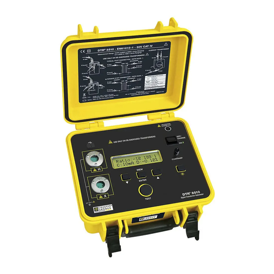
2.2. DESCRIPTION DES COMMANDES USE SPECIFIED CHARGER ONLY USE ONLY ON DE-ENERGIZED TRANSFORMERS OFF/ CHARGE CONTRAST ENTER 50V CAT IV TEST 8510 ® Digital Transformer Ratiometer Écran : affiche les résultats de mesure, l’état et les fonctions de commande de l’appareil. Connecteur USB : Permet le branchement à... - Page 7 Cordons de l’enroulement secondaire (X) : FICHE DE BRANCHEMENT ROUGE IDENTIFICATEUR « X » CONNECTEUR 3 BROCHES JEU DE CORDONS X IDENTIFICATEUR « X » FICHE DE BRANCHEMENT NOIRE Chaque cordon est clairement identifié. Le cordon de l’enroulement primaire (H) comporte un connecteur à 5 broches et le cordon de l’enroulement secondaire (X) comporte un connecteur à...
-
Page 8: Caractéristiques Techniques
3. CARACTÉRISTIQUES TECHNIQUES Conditions de référence : 23°C ± 5°C (Humidité relative de 30 à 50%). Ajouter 25 ppm/°C entre -10 et 18°C et entre 28 et 50°C à toutes les caractéristiques de précision. Aucune présence de champ électrique ou magnétique. Courant de sortie ≤150 mA pour TV/TP et ≤... -
Page 9: Caractéristiques Techniques Du Chargeur De Batteries
CARACTÉRISTIQUES ENVIRONNEMENTALES Température de fonctionnement -10° à 50°C Température de stockage - 20°C à + 60°C Humidité relative 10 à 85% HR @ 35°C Altitude Jusqu'à 2000 mètres SÉCURITÉ Conformité EN 61010-1; 50 V CAT IV ; Degré de pollution 2 Double isolement Les caractéristiques techniques sont soumises à... -
Page 10: Fonctions D'affichage
4. FONCTIONS D’AFFICHAGE 4.1. ORGANIGRAMME DU PROGRAMME Afin d’utiliser l’appareil efficacement, il est important de comprendre l’organigramme du programme. „ La pression simultanée des touches et permet de remonter d’un niveau (s’il y en a un) dans l’organigramme du programme. (Navigation verticale remontant d’un niveau). - Page 11 „ Mettre à l’heure : Permet de régler l’heure et la date. „ Entrer la plaque signalétique : Permet de sélectionner et de modifier les tensions ou les rapports portés sur la plaque si- gnalétique présente. Des rapports prédéfinis seulement peuvent être modifiés avec DataView ®...
- Page 12 La configuration Mettre à l’heure permet de régler l’heure aux formats suivants : Format Date : Permet de sélectionner le format de la date. (MM/JJ/AA, JJ/MM/AA ou AA/MM/JJ). Figure 4-6 Format heure : Permet de formater l’heure (12 ou 24 heures). Figure 4-7 Entrer la Date et L’heure : Permet de régler la date et l’heure au format sélectionné.
- Page 13 „ Chaque résultat de mesure enregistrera la plaque signalétique présente avec les autres paramètres associés et sera disponible lorsque les données seront téléchargées. „ Les valeurs des rapports des plaques signalétiques doivent être comprises entre 1 et 32767. „ La fonction de plaque signalétique doit être activée. Si elle ne l’est pas, l’écart en % ne sera pas rapporté après les mesures. Ensuite, les valeurs enregistrées n’auront pas de plaque signalétique et d’écart en % indiqués dans les résultats de mesure.
- Page 14 REMARQUE : „ la sélection d’un transformateur de la liste remplacera immédiatement les valeurs de la plaque signalétique présente. Les valeurs peuvent alors être modifiées dans le mode Editer si nécessaire „ La sélection d’Editer permettra à l’utilisateur de modifier les valeurs de la plaque signalétique présente. „...
- Page 15 4.3.5. SÉLECTIONNER MODE ENREGISTREMENT A partir du niveau supérieur de Configurer l’appareil, appuyer sur la touche ou jusqu’à ce que Sélectionner Mode enregistre. apparaisse à l’écran, et appuyer ensuite sur ENTER. Figure 4-16 Sélectionner Auto ou Manuel à l’aide de ou et appuyer sur ENTER. L’écran retournera à Configurer l’appareil > Sélectionner Mode enregistre.
- Page 16 Le DTR 8510 améliore la qualité des mesures des manières suivantes : ® „ Circuits électroniques à faible bruit „ Circuits électroniques et cordons blindés. „ Mesures différentielles pour réduire les effets de mode commun. „ Calculs quotient métriques pour réduire les erreurs dynamiques. TV/TP Rapide Normal...
-
Page 17: Rappel Des Données
REMARQUE : la langue peut également être sélectionnée immédiatement au démarrage. Appuyer et maintenir le bouton TEST tout en mettant l’appareil sous tension. Après l’initialisation, l’appareil affichera la langue active actuellement. Relâcher le bouton TEST. La langue désirée peut à présent être sélectionnée. 4.3.9. - Page 18 Figure 4-21 Appuyer sur le bouton TEST pour passer au deuxième écran qui affichera le Courant et l’Ecart en %. Figure 4-22 Appuyer sur le bouton TEST pour passer au troisième écran qui affichera la date et l’heure. Figure 4-23 Appuyer sur le bouton TEST pour passer au quatrième écran qui affichera les tensions des enroulements primaire et secon- daire de la plaque signalétique présente au moment où...
-
Page 19: Utilisation
5. UTILISATION AVERTISSEMENT : Le DTR 8510 est conçu pour un usage avec des transformateurs hors tension (« état passif ») seu- ® lement. Veiller à ce que le transformateur testé soit totalement débranché de toute alimentation en courant alternatif et qu’il soit totalement déchargé. - Page 20 - Connexion typique RAPPORT 2,767 : 1 ENROULEMENT SECONDAIRE ENROULEMENT PRIMAIRE ROUGE ROUGE ROUGE 19920 : 7200CT NOIR NOIR ROUGE NOIR NOIR - Autre connexion possible RAPPORT 1,383 : 1 ROUGE ENROULEMENT SECONDAIRE ENROULEMENT PRIMAIRE 19920 : 7200CT NOIR ROUGE ROUGE NOIR NOIR...
- Page 21 Dans cet exemple, un écran semblable à celui ci-dessous apparaîtra. Figure 5-4 Si les branchements H/X sont inversés, l’appareil affichera le message d’erreur suivant et mettra fin au test. Figure 5-5 REMARQUE : „ S’il existe une inversion de polarité, le rapport sera affiché sous forme d’une valeur négative et clignotera. Cela signifie que les branchements sont inversés du côté...
- Page 22 REMARQUE : si le résultat de mesure enregistré précédemment est rencontré, le mode d’enregistrement automatique le sautera et enregistrera le nouveau résultat de mesure à l’emplacement suivant disponible. 5.2.3. COURANT D’EXCITATION TV/TP Le courant d’excitation, affiché en milli-ampères (mA), est la valeur efficace du courant dans l’enroulement primaire (H) dû à l’excitation de test.
-
Page 23: Conseils Pour La Réalisation De Mesures De Rapport Précises
Brancher le cordon de l’enroulement (H) primaire aux connecteurs appropriés du DTR 8510 et du transformateur testé. ® Brancher le cordon de l’enroulement secondaire (X) comme une boucle à travers l’ouverture du transformateur de courant comme le montre la figure. NOIR ROUGE ROUGE... -
Page 24: Test De Rapport - 1:1
5.4. TEST DE RAPPORT - 1:1 Un test simple peut être effectué pour vérifier la fonctionnalité du DTR 8510. ® Brancher le cordon HROUGE au cordon XROUGE d’une part et le cordon HNOIR au cordon XNOIR d’autre part. Ce bran- chement simule un transformateur 1:1. -
Page 25: Branchements
6. BRANCHEMENTS 6.1. SCHÉMAS DE BRANCHEMENTS Vérifier que le cordon H est toujours branché de telle manière qu’il ne soit pas relié directement au cordon X ROUGE ROUGE ou à travers la connexion de terre. NOIR Parmi les schémas ci-dessous, les trois schémas supérieurs sont corrects, mais celui inférieur doit être évité. REMARQUE : HB/XB signifie H noir / X noir Mesures - CORRECTES HR/HB... -
Page 26: Branchements Polyphasés
6.2. BRANCHEMENTS POLYPHASÉS ENROU- ENROU- RAPPORT - TRANSFORMATEUR - N° LEMENT LEMENT TYPE PHASE ENROULEMENT ENROULEMENT HAUTE BASSE TRANSFOR- XFMR TENSION TENSION MATION HAUTE TENSION BASSE TENSION 1 Ø 1 Ø ∆ ∆ ∆ ∆ √ ∆ H • ∆ √... -
Page 27: Logiciel Dataview
7. LOGICIEL DATAVIEW ® 7.1. INSTALLATION DE DATAVIEW ® NE PAS BRANCHER L’APPAREIL A L’ORDINATEUR AVANT D’INSTALLER LE LOGICIEL ET LES PILOTES. bla bbla Conditions minimales pour l’ordinateur : „ Windows XP / Windows Vista & Windows 7 (32/64 bits) „... - Page 28 „ *Firmware Upgrades - Lien vers les mises à jour du microprogramme Chauvin-Arnoux pour rechercher de nouvelles ver- ® sions de ce micrologiciel. „ Documents - Affiche une liste de documents se rapportant à l’appareil, et pouvant être affichés. Adobe Reader est nécessaire ®...
-
Page 29: Ouverture Du Panneau De Configuration
14. Redémarrer l’ordinateur, et brancher ensuite l’appareil à l’ordinateur. 15. Une fois l’appareil branché, la boîte de dialogue Nouveau matériel détecté s’affiche. Windows terminera automatiquement le processus d’installation du pilote. Des raccourcis pour Dataview et pour chaque panneau de configuration d’appareil sélectionné pendant le processus d’instal- ®... -
Page 30: Utilisation Du Panneau De Configuration
Sélectionner Configurer l’instrument. La boîte de dialogue Sélectionner l’instrument s’affichera. Figure 7-6 Sélectionner DTR et cliquer sur OK. La boîte de dialogue Connexion s’affichera (voir la Fig. 7-4). La fenêtre Connexion détermine l’appareil branché dans la liste déroulante des communications. Si plusieurs appareils sont branchés, sélectionner l’appareil désiré... -
Page 31: Configurer Le Dtr ® 8510
Imprimer tous les tests - Imprime tous les tests contenus dans l’objet sélectionné Imprimer - Imprime la fenêtre sélectionnée en temps réel Aperçu de tous les tests avant impression - Présente un aperçu de tous les tests à imprimer Configuration imprimante - Affiche une fenêtre de configuration d’imprimante permettant de sélectionner une imprimante de destination et de modifier diverses options d’impression Quitter - Ferme le panneau de configuration Édition... -
Page 32: Exécution D'un Test
Format de date : Permet de sélectionner le format de la date selon MM/JJ/AA ou JJ/MM/AA ou AA/MM/JJ. Format de l’heure : Permet de sélectionner le format de l’heure selon le format 24 heures ou 12 heures. Type de test par défaut : Permet de sélectionner le test TV/TP ou TC. Mode de test par défaut : Permet de sélectionner le mode de test de Rapport seulement ou de Cont/Rapport (Continuité... -
Page 33: Téléchargement D'un Test
REMARQUE : „ Si le DTR 8510 est en mode d’enregistrement automatique, la connexion à l’ordinateur désactivera l’enregistrement auto- ® matique du résultat de mesure. „ Si le test doit être annulé pendant qu’il est en cours, appuyer sur le bouton TEST de l’appareil ou sur le bouton ANNULER de l’écran. -
Page 34: Enregistrer Les Résultats De Mesure
7.7. ENREGISTRER LES RÉSULTATS DE MESURE Sélectionner Enregistrer ou Enregistrer sous dans le menu Fichier. La boîte de dialogue Enregistrer sous s’affichera : Figure 7-13 Enregistrer le fichier dans le dossier par défaut « Mes documents\DataView\DataFiles\DTR » ou sélectionner un dossier différent. - Page 35 REMARQUE : „ Tous les fichiers et les comptes-rendus téléchargés sont enregistrés dans le dossier par défaut « Mes documents » ou « Documents » de chaque utilisateur „ DataView et Panneau de configuration (PC) sont des programmes totalement intégrés pour le contrôle d’appareils et la créa- tion d’analyse de données et de compte-rendu.
-
Page 36: Maintenance
8. MAINTENANCE Le fabricant ne pourra être tenu pour responsable de tout accident survenu suite à une réparation effectuée en dehors de son service après-vente ou des réparateurs agréés. 8.1. CHARGEMENT DES BATTERIES Le DTR 8510 est fourni avec un chargeur intelligent. Pour charger les blocs de batteries NiMH, l’interrupteur de l’appareil doit ®... -
Page 37: Nettoyage
Le chargeur intelligent comporte les caractéristiques suivantes : „ Méthodes de détection de charges multiples -dV (typique) et dT/dt. Normalement, la charge complète de la batterie est détectée par une légère chute de sa tension (-dV). En revanche, si les batteries sont inutilisées pendant une longue durée, elles peuvent présenter la même chute de tension au début du cycle de charge même si elles ne sont pas complètement chargées. -
Page 38: Vérification Métrologique
Tél. : 02 31 64 51 43 - Fax : 02 31 64 51 09 8.4. RÉPARATION Pour les réparations sous garantie et hors garantie, contactez votre agence commerciale Chauvin Arnoux la plus proche ou votre centre technique régional Manumesure qui établira un dossier de retour et vous communiquera la procédure à suivre. -
Page 39: Annexe : Messages Affichés
9. ANNEXE : MESSAGES AFFICHÉS Vérifier l’inversion des cordons H<>X Le DTR 8510 peut avoir détecté une condition potentiellement à risque lorsqu’il a tenté de tester le transformateur ainsi connecté. ® Vérifier les branchements. Courant d’excitation fort Vérifier que les cordons de test ne sont pas en court-circuit accidentel. Vérifier que les enroulements du transformateur ne sont pas en court-circuit. -
Page 40: Garantie
10. GARANTIE Notre garantie s’exerce, sauf stipulation expresse, pendant douze mois après la date de mise à disposition du matériel. L’extrait de nos Conditions Générales de Vente est communiqué sur demande. La garantie ne s’applique pas suite à : „ une utilisation inappropriée de l'équipement ou à une utilisation avec un matériel incompatible ; „... -
Page 41: Pour Commander
11. POUR COMMANDER Mesureur numérique de rapport de transformation DTR 8510 ................P01157702 ® Livré avec une sacoche de transport contenant : „ un cordon secteur, „ un jeu de cordons de mesure, „ un chargeur de batterie 90-260V, „ une fiche d’utilisation de la batterie, „... - Page 42 ENGLISH Thank you for purchasing a digital transformer ratiometer DTR 8510. ® For best results from your instrument: „ read these operating instructions carefully, „ comply with the precautions for use. WARNING, risk of DANGER! The operator must refer to these instructions whenever this danger symbol appears. Equipment protected by double insulation.
- Page 43 CONTENTS 1. PRECAUTIONS FOR USE..............................44 1.1. Receiving Your Shipment ............................44 2. PRODUCT FEATURES ................................45 2.1. Description ................................... 45 2.2. Control Features ................................46 2.3. Cable Identification ..............................47 3. SPECIFICATIONS ................................... 48 3.1. DTR 8510 Specifications ............................48 ®...
-
Page 44: Precautions For Use
1. PRECAUTIONS FOR USE These safety warnings are provided to ensure the safety of personnel and proper operation of the instrument. „ This instrument is protected from accidental voltages of not more than 50 V with respect to earth. The guaranteed level of protection of this equipment may be compromised if used in a manner not specified by the manufacturer. -
Page 45: Product Features
2. PRODUCT FEATURES 2.1. DESCRIPTION The Digital Transformer Ratiometer DTR 8510 is a lightweight, rugged, portable instrument designed for onsite testing of power, ® potential and current transformers. Operation of the DTR 8510 is fully automatic. No user calibration, range selection, hand cranking or tedious balancing is required. ®... -
Page 46: Control Features
2.2. CONTROL FEATURES USE SPECIFIED CHARGER ONLY USE ONLY ON DE-ENERGIZED TRANSFORMERS OFF/ CHARGE CONTRAST ENTER 50V CAT IV TEST 8510 ® Digital Transformer Ratiometer Display: Displays data, status and control features of the instrument. USB Connector: Allows connection to a computer for instrument configuration set-up and status check, downloading of the stored data using the DataView software and running a test. -
Page 47: Cable Identification
2.3. CABLE IDENTIFICATION Primary (H) Cable: RED INLINE PLUG "H" IDENTIFIER 5 PIN CONNECTOR H CABLE SET "H" IDENTIFIER BLACK INLINE PLUG Secondary (X) Cable: RED INLINE PLUG "X" IDENTIFIER 3 PIN CONNECTOR X CABLE SET "X" IDENTIFIER BLACK INLINE PLUG Each cable is clearly marked. -
Page 48: Specifications
3. SPECIFICATIONS Reference Conditions: 23°C ± 5°C (30 to 50% RH) range. Add 25 ppm/°C from -10 to 18°C and 28 to 50°C to all accuracy specifications. No external electrical or magnetic fields. Output current ≤150 mA for VT/PT and ≤ 50 mA for CT. Calibration cycle is 1 year. -
Page 49: Battery Charger Specifications
ENVIRONMENTAL Operating Temperature -10° to 50°C Storage Temperature -20° to 60°C Relative Humidity 10 to 85% RH @ 35°C Altitude Up to 2000 meters (6560 ft) SAFETY Safety Rating EN 61010-1; 50 V CAT IV; Pollution Degree 2 Double Insulated CE Marking Pending Specifications are subject to change without notice. -
Page 50: Display Functions
4. DISPLAY FUNCTIONS 4.1. PROGRAM FLOW In order to use the instrument efficiently, it is important to understand the program flow. „ Pressing the and keys simultaneously allows going up one level (if there is a level) in the program flow. (Vertical naviga- tion moving up a level). - Page 51 „ Set Clock: Allows the setting of Time and Date. „ Setup Nameplate: Allows selection and editing of Present Nameplate voltages or ratios. Predefined ratios can only be edited through DataView ® „ Select Test Type: Allows the selection of Test Type (VT/PT or CT). „...
- Page 52 The Set Clock configuration allows you to format the following: Date Format: Allows the formatting of the date. (MM/DD/YY, DD/MM/YY, YY/MM/DD). Figure 4-6 Time Format: Allows the formatting of the time (12 or 24 hours). Figure 4-7 Set Date and Time: Allows the setting of the date and time in the selected format. Note: Time must be set in the 24-hour format.
- Page 53 „ Each Measurement Record will record the Present Nameplate along with other associated parameters and will be available when the data is downloaded. „ The Ratio of the nameplate values must be between 1 and 32767. „ The Nameplate needs to be enabled. If the Nameplate is not enabled, the Deviation % will not be reported after the measure- ments.
- Page 54 NOTE: „ Selecting one transformer from the list will replace the values in the Present Nameplate immediately. The values can then be changed in the Edit mode if needed. „ Selecting Edit will allow the user to modify the values in the Present Nameplate. „...
- Page 55 4.3.5. SELECT STORAGE MODE From the top level of Configure Instrument, press the or key until Select Storage Mode appears on the display, then press ENTER. Figure 4-16 Select Auto or Manual using or and press ENTER. The display will return to Configure Instrument > Select Storage Mode.
- Page 56 The DTR 8510 improves the quality of measurements in the following ways: ® „ Low noise electronics „ Shielded electronics and cables. „ Differential measurements to reduce common-mode effects. „ Ratiometric calculations to reduce dynamic errors. VT/PT Fast Normal Slow 6.5 S 19 S Approx Measurement Time...
-
Page 57: Recall Data
NOTE: The language can also be selected immediately at start up. Press and hold the TEST button while turning the unit ON. After initialization, the instrument will display the currently active language. Release the TEST button. The desired language can now be selected. 4.3.9. - Page 58 Figure 4-21 Press the TEST button to move to second screen, which will display Current and Deviation %. Figure 4-22 Press the TEST button to move to the third screen to display the Date and Time. Figure 4-23 Press the TEST button to move to the fourth screen to display the Primary and Secondary voltages of the Present Nameplate at the time the measurement was made.
-
Page 59: Operation
5. OPERATION WARNING: The DTR 8510 is designed for use on de-energized (“dead”) transformers only. Make sure the test sample is ® completely disconnected from AC power and is fully discharged. 5.1. POWER UP Turn the power switch to the ON position. At power up, the instrument goes through an initialization process: „... - Page 60 - Typical Connection RATIO 2.767 : 1 SECONDARY PRIMARY 19920 : 7200CT BLACK BLACK BLACK BLACK - Alternate Connection RATIO 1.383 : 1 PRIMARY SECONDARY 19920 : 7200CT BLACK BLACK BLACK BLACK Figure 5-2 Connect the Primary (H) and Secondary (X) cables to the appropriate connectors on the DTR 8510 and the transformer under test ®...
- Page 61 In this example, the display will appear as shown below. Figure 5-4 If the H/X were reversed, the instrument will display the following error message and terminate the test. Figure 5-5 NOTE: „ If there were a polarity reversal, the Ratio would be displayed negative and it would be blinking. This means either the con- nections are reversed on a given side or the transformer is wound backwards relative to the marking.
- Page 62 5.2.3. VT/PT EXCITATION CURRENT Excitation current, displayed in milli-amperes (mA) is the RMS current in the Primary (H) winding due to test excitation. The load- ing on the Secondary (X) winding due to the DTR 8510 is negligible. ® „ The DTR 8510 uses a maximum of 32 Vrms excitation voltage for testing.
-
Page 63: Tips For Making Precise Ratio Measurements
Connect the Primary (H) cable to the appropriate connectors on the DTR 8510 and the transformer under test. Connect the ® Secondary (X) cable as a loop through the current transformer hole as shown in the figure. BLACK BLACK Figure 5-7 Press the TEST button. -
Page 64: Ratio Test - 1:1
5.4. RATIO TEST - 1:1 A simple test can be conducted to test functionality of the DTR 8510. ® Connect the H to X cable and separately connect the H to X . This connection simulates a 1:1 transformer. BLACK BLACK Run VT/PT test. -
Page 65: Connections
6. CONNECTIONS 6.1. CONNECTION DIAGRAMS Make sure that the H lead is always connected such that it does not short to the X or X lead directly or through BLACK earth ground. In the diagrams below, the top three are good connections but the bottom two should be avoided. Measurements - OK HR/HB XR/XB... -
Page 66: Polyphase Connections
6.2. POLYPHASE CONNECTIONS - TRANSFORMER - HIGH XFMR TURNS PHASE VOLTAGE VOLTAGE HIGH VOLTAGE LOW VOLTAGE TYPE RATIO WINDING WINDING WINDING WINDING 1 Ø 1 Ø ∆ ∆ ∆ ∆ √ ∆ H • ∆ √ H • ∆ √ X •... -
Page 67: Dataview ® Software
7. DATAVIEW SOFTWARE ® 7.1. INSTALLING DATAVIEW ® DO NOT CONNECT THE INSTRUMENT TO THE PC BEFORE INSTALLING THE SOFTWARE AND DRIVERS. Text text text text. Minimum Computer Requirements: „ Windows XP / Windows Vista & Windows 7 (32/64 bit) „... - Page 68 „ Documents - Shows a list of instrument related documents that you can view. Adobe Reader is required for viewing PDF ® documents supplied with DataView ® DataView, Version x.xx.xxxx option should be selected by default. Select the desired language and then click on Install. The Installation Wizard window will appear.
-
Page 69: Opening The Control Panel
Shortcuts for DataView and each instrument control panel selected during the installation process have been added to your ® desktop. NOTE: If you connected your instrument to the computer before installing the software and drivers, you may need to use the Add/Remove Hardware utility to remove the instrument driver before repeating the process. -
Page 70: Using The Control Panel
Select Configure Instrument. The Select Instrument dialog box will appear. Figure 7-6 Select DTR and press OK. The Connection dialog box will appear (see Fig. 7-4). The Connection window specifies the connected instrument in the communications drop-down list. If multiple units are attached, select the desired unit with its associated serial number from the drop-down list. Once the desired instrument has been selected, click OK and the DTR 8510 Control Panel and Configuration window will open ®... -
Page 71: Configuring The Dtr ® 8510
Print All Tests - Prints all the tests in the selected Object Print - Prints the selected real-time window Print Preview All Tests - Provides a preview of all tests to be printed Print Setup - Displays a Print Setup window allowing you to select a destination printer and change various printing options Exit - Closes the control panel Edit Edit - Edits the session information for the selected test in the opened *.icp file... -
Page 72: Running A Test
Date Format: Allows selection of the Date Format as MM/DD/YY or DD/MM/YY or YY/MM/DD. Time format: Allows selection of Time format as 24-hour or 12-hour format. Default Test Type: Allows selection of VT/PT or CT test. Default Test Mode: Allows selection of test for Ratio only or Cont/Ratio (Continuity and Ratio) mode. Default Storage Mode: Allows selection of storage of each Measurement Record in Manual or Automatic mode. -
Page 73: Downloading A Test
NOTE: „ If the DTR 8510 is in Autosave mode, the connection to the computer will disable the automatic saving of the Measurement ® Record. „ If the Test needs to be cancelled while testing is in progress, press the TEST button on the instrument or CANCEL button on the screen. -
Page 74: Saving The Measurement Records
7.7. SAVING THE MEASUREMENT RECORDS Select Save or Save As from the File menu. The Save As dialog box will appear: Figure 7-13 Save the file in the default location of “My Documents\DataView\DataFiles\DTR” or select a different folder to save to. 7.8. - Page 75 NOTE: „ All downloaded files and reports are saved in the default location of “My Documents” or “Documents” for each user. „ DataView and Control Panel (CP) are fully integrated programs for instrument control and data analysis/report generation. ® CP can download the Measurement Records previously stored in the DTR 8510 memory.
-
Page 76: Maintenance
8. MAINTENANCE The manufacturer cannot be held liable for any accident that occurs following a repair not performed by its cus- tomer service department or by an approved repairer. 8.1. CHARGING THE BATTERIES The DTR 8510 is supplied with an external smart charging unit. In order to charge the NiMH battery packs, the instrument switch ®... -
Page 77: Cleaning
The smart charger has the following features: „ Multiple charge detection methods -dV (typical) and dT/dt. Typically, the indication that the battery is fully charged is detected by a slight drop in its voltage (-dV). However, if the batteries are unused for a long time, they may display the same drop in voltage in the early part of the charge cycle even if they are not fully charged. -
Page 78: Metrological Check
This instrument should be checked at least once a year. For checking and calibration, contact one of our accredited metrology laboratories (information and contact details available on request), at our Chauvin Arnoux subsidiary or the branch in your country. 8.4. REPAIR... -
Page 79: Appendix: Display Messages
9. APPENDIX: DISPLAY MESSAGES Check for H<>X Cable Reversal The DTR 8510 may have detected a potentially hazardous step-up condition while attempting to test the transformer as con- ® nected. Verify connections. High Excitation Current Check test cable connections for inadvertent short circuits. Check for shorted transformer windings. Low Battery As the batteries are drained during use, the green LED will begin to flash when the battery voltage reaches a pre-determined threshold. -
Page 80: Warranty
10. WARRANTY Except as otherwise stated, our warranty is valid for twelve months starting from the date on which the equipment was sold. Extract from our General Conditions of Sale provided on request. The warranty does not apply in the following cases: „... -
Page 81: To Order
11. TO ORDER Digital Transformer Ratiometer DTR 8510 ......................P01157702 ® Delivered with a carrying bag containing : „ a power cord, „ a set of measuring cables, „ an external battery charger 90-260V, „ a battery user instruction sheet, „... - Page 82 DEUTSCH Sie haben ein Digitales Prüfgerät der Übersetzungsverhältnisse DTR 8510 gekauft und wir danken Ihnen für Ihr Vertrauen. ® Für die Erlangung eines optimalen Betriebsverhaltens Ihres Instrumentes: „ Lesen Sie bitte diese Betriebsanleitung aufmerksam durch und „ befolgen Sie die Sicherheitshinweise. ACHTUNG, GEFAHR! Der Bediener muss jedes Mal die Anleitung zu Rate ziehen, wenn dieses Gefahrenzeichen auftritt.
- Page 83 INHALTSVERZEICHNIS 1. SICHERHEITSHINWEISE ..............................84 1.1. Paketannahme ................................84 2. PRODUKTEIGENSCHAFTEN ..............................85 2.1. Beschreibung ................................85 2.2. Beschreibung der Befehle ............................86 2.3. Kennzeichnung der Messleitungen ..........................86 3. TECHNISCHE DATEN ................................88 3.1. Technische Daten des DTR 8510 ..........................88 ®...
-
Page 84: Sicherheitshinweise
1. SICHERHEITSHINWEISE Diese Warnhinweise sollen den Bedienerschutz und eine korrekte Bedienung des Instruments gewährleisten. „ Das Instrument besitzt einen Überlastschutz von bis zu 50V gegen Erde. Die Schutzklasse des Instruments ist nur dann ge- währleistet, wenn es nach Herstellerangaben verwendet wird. „... -
Page 85: Produkteigenschaften
2. PRODUKTEIGENSCHAFTEN 2.1. BESCHREIBUNG Das digitale Prüfinstrument der Übersetzungsverhältnisse DTR 8510 ist ein leichtes und robustes, tragbares Instrument für die ® Vor-Ort-Prüfung von Leistungs-, Spannungs- und Stromtransformatoren. Die Überprüfung mit DTR 8510 erfolgt vollautomatisch! Kein umständliches Kalibrieren, Bereichswählen, manuelles Starten und ®... -
Page 86: Beschreibung Der Befehle
2.2. BESCHREIBUNG DER BEFEHLE USE SPECIFIED CHARGER ONLY USE ONLY ON DE-ENERGIZED TRANSFORMERS OFF/ CHARGE CONTRAST ENTER 50V CAT IV TEST 8510 ® Digital Transformer Ratiometer Anzeige: Anzeige von Messergebnissen, Status und Befehlsfunktionen des Instruments. USB-Anschluss: Zum Anschluss an einen Computer zwecks Konfiguration und Kontrolle des Instruments, Hochladen der mit DataView abgespeicherten Ergebnisse und Starten eines Prüfdurchgangs. -
Page 87: Kennzeichnung Der Messleitungen
2.3. KENNZEICHNUNG DER MESSLEITUNGEN Primärkreis-Leitungen (H): ROTER STECKER MARKIERUNG „H“ 5 POLIGE STECKVERBINDUNG SATZ H-LEITUNGEN MARKIERUNG „H“ SCHWARZER STECKER Sekundärkreis-Leitungen (X): ROTER STECKER MARKIERUNG „X“ 3 POLIGE STECKVERBINDUNG SATZ X-LEITUNGEN MARKIERUNG „X“ SCHWARZER STECKER Alle Leitungen sind eindeutig gekennzeichnet. Die Leitung der Primärwicklung (H) besitzt eine 5-polige Steckverbindung, die Sekundärwicklung (X) eine 3-polige Steckverbindung, sodass eine Verwechslung augeschlossen ist. -
Page 88: Technische Daten
3. TECHNISCHE DATEN Referenzbedingungen: 23°C ± 5°C (Relative Feuchtigkeit 30 bis 50%). Bei -10 und 18°C bzw. 28 und 50°C sind für alle Genauigkeitsangaben 25 ppm/°C hinzuzurechnen. Kein elektrisches oder Magnetfeld. Ausgangsstrom 150 mA bei VT/PT und 50 mA bei CT. Kalibrierung ein Mal jährlich. 3.1. -
Page 89: Technische Daten Des Akku-Ladegeräts
UMWELTDATEN FÜR DEN GERÄTEBETRIEB Betriebstemperatur -10°C bis + 50°C Lagertemperatur - 20°C bis + 60°C Relative Luftfeuchtigkeit 10 bis 85% RH @ 35°C Höhenlage Bis 2000 Meter SICHERHEIT Konformität EN 61010-1; 50 V KAT IV; Verschmutzungsgrad 2 Doppelschirmung Die technischen Daten können ohne Vorankündigung geändert werden. 3.2. -
Page 90: Anzeigefunktionen
4. ANZEIGEFUNKTIONEN 4.1. PROGRAMMAUFBAU Für eine effiziente Instrumentenutzung ist es wichtig, den Programmaufbau zu verstehen. „ Drückt man die beiden folgenden Tasten und gleichzeitig, gelangt man in die nächsthöhere Programmebene (wenn vorhanden). (senkrechtes Umschalten auf die nächsthöhere Ebene). „ Betätigt man die Taste oder , bewegt man sich innerhalb der Ebene weiter. (waagrechtes Umschalten). „... - Page 91 „ Einstellung Uhr: Uhrzeit und Datum einstellen. „ Setup Typenschild: Auswählen und ändern der auf dem vorhandenen Typenschild angeführten Spannungen und Verhältnisse. Nur voreingestellte Verhältnisse können mit Dataview geändert werden. ® „ Auswahl Test-Typ: Auswählen der Test-Typ (VT/PT oder CT). „...
- Page 92 Beim Einstellen von Einstellung Uhr stehen folgende Zeit-Formate zur Verfügung: Datum-Format: Auswählen des Datum-Formats. (MM/TT/JJ, TT/MM/JJ oder JJ/MM/TT). Abb. 4-6 Zeit-Format: Auswählen des Zeit-Formats (12- oder 24-Stunden-Format). Abb. 4-7 Einstellung Datum+Uhrzeit: Einstellen von Datum und Uhrzeit im gewählten Format. Anmerkung: Die Uhrzeit sollte im 24-Stunden-Format eingestellt werden, im 12-Stunden-Format wird sie mit AM/PM angezeigt. Abb.
- Page 93 „ Die Funktion „Typenschild“ muss angewählt sein, weil sonst nach dem Messen die %-Abweichung nicht angeführt wird, für die Speicherwerte kein Typenschild zur Verfügung steht und keine %-Abweichung in den Messergebnissen aufscheint. ANMERKUNG: Das aktuelle Typenschild erscheint nur dann auf der Hauptanzeige, wenn die Typenschild-Funktion ange- wählt ist, andernfalls erscheint für die Primär- und Sekundärwicklung nur „---“.
- Page 94 ANMERKUNG: „ Die aktuellen Typenschild-Werte werden sofort angewendet, sobald ein Transformator auf der Liste ausgewählt wird. Die Werte lassen sich im Modus Bearbeiten gegebenenfalls „ Über d’Bearbeiten kann der Benutzer die aktuellen Typenschild-Werte abändern. „ Diese Bearbeitung wird aber nur für die aktuellen Typenschild-Werte übernommen, die ursprünglich eingespeicherten Listenwerte bleiben davon unberührt! Liste lassen sich nur mit Hilfe von DataView ändern.
- Page 95 4.3.5. AUSWAHL SPEICHER-MODUS Ausgehend von der Programmebene Instrument konfigurieren betätigen Sie die Tasteoder bis Auswahl Speicher-Modus auf der Anzeige erscheint, dann mit ENTER bestätigen. Abb. 4-16 Wählen Sie Autooder Manuell mit Hilfe von oder und bestätigen Sie mit ENTER. Auf der Anzeige erscheint nun wieder Instrument konfigurieren >...
- Page 96 8510 verbessert die Qualität der Messungen gleich mehrfach: ® „ Elektronische Schaltkreise mit schwachem Rauschen „ Elektronische Schaltkreise und geschirmte Leitungen „ Differentialmessungen reduzieren die Auswirkungen des Gleichtakts „ Metrische Quotientenberechnungen reduzieren die dynamischen Fehler. VT/PT Schnell Normal Langsam Ungefähre Messdauer 6,5 s 19 s Umfeld...
-
Page 97: Daten Aufrufen
ANMERKUNG: Die Sprache kann auch sofort beim Start gewählt werden. Dazu hält man beim Hochfahren des Instruments die Taste TEST gedrückt. Nach der Initialisierung zeigt das Instrument die aktuelle Sprachwahl an. Lassen Sie nun die Taste TEST los und wählen Sie die gewünschte Sprache. 4.3.9. - Page 98 Abb. 4-21 Betätigen Sie die Taste TEST zum Umschalten auf die zweite Anzeige, auf der der Strom und die %-Abweichung angezeigt sind. Abb. 4-22 Betätigen Sie die Taste TEST zum Umschalten auf die dritte Anzeige mit Datum und Uhrzeit. Abb. 4-23 Betätigen Sie die Taste TEST zum Umschalten auf die vierte Anzeige mit den Typenschild-Spannungsangaben der Primär- und Sekundärwicklungen zum Zeitpunkt der Messung.
-
Page 99: Bedienung
5. BEDIENUNG WARNHINWEIS: DTR 8510 ist für die Prüfung von spannungsfreien (passiven) Transformatoren ausgelegt. Achten Sie ® darauf, dass der geprüfte Transformator an keinerlei AC-Stromversorgung angeschlossen und vollständig entladen ist. 5.1. EINSCHALTEN Schalter auf ON stellen. Sobald das Instrument unter Spannung steht, läuft eine Initialisierung ab: „... - Page 100 - typische Verbindung VERHÄLTNIS 2,767: 1 SEKUNDÄRWICKLUNG PRIMÄRWICKLUNG H ROT H ROT X ROT 19920 : 7200CT H SCHWARZ X SCHWARZ X ROT H SCHWARZ X SCHWARZ - Sonstige Verbindungsmöglichkeiten VERHÄLTNIS 1,383: 1 H ROT SEKUNDÄRWICKLUNG PRIMÄRWICKLUNG 19920 : 7200CT X SCHWARZ X ROT H ROT...
- Page 101 In unserem Beispiel erscheint folgende Anzeige. Abb. 5-4 Bei vertauschten H/X Anschlüssen erscheint folgende Fehlermeldung und die Überprüfung wird abgebrochen. Abb. 5-5 ANMERKUNG: „ Bei vertauschter Polarität erscheint ein negativer Wert, der blinkt, was bedeutet, dass die Anschlüsse an dieser Seite vertauscht sind oder dass der Transformator in die andere Richtung gewickelt ist.
- Page 102 ANMERKUNG: Wenn das Instrument beim automatischen Abspeichern auf ein früheres Messergebnis trifft, überspringt es dieses und speichert das neue Messergebnis am ersten freien Speicherplatz ab. 5.2.3. ERREGERSTROM VT/PT Der Erregerstrom (Anzeige in Milliampère mA) ist der Effektivwert des Stroms in der Primärwicklung (H) aufgrund der Testerregung. Die Last in der Sekundärwicklung (X) durch das DTR 8510 ist zu vernachlässigen.
-
Page 103: Tipps Für Genaueres Messen Der Übersetzungsverhältnisse
Die Leitungen der Primärwicklung (H) und Sekundärwicklung (X) an den DTR 8510 und an den überprüften Transformator ® anschließen. H SCHWARZ H ROT X SCHWARZ X ROT Abb. 5-7 Taste TEST drücken. Vor der Überprüfung des Übersetzungsverhältnisses prüft das Instrument auf eventuell vertauschte Polarität H/X, Kurzschlüsse usw. -
Page 104: Verhältnistest - 1:1
5.4. VERHÄLTNISTEST - 1:1 Mit einem einfachen Test lässt sich überprüfen, ob das 8510 in einwandfreier Betriebsbereitschaft ist. Verbinden Sie die Leitung HROT mit der Leitung XROT, und die Leitung HSCHWARZ mit der Leitung XSCHWARZ. Dieser Anschluss simuliert einen 1:1 Transformator. Nehmen Sie einen VT/PT Test vor. -
Page 105: Anschlüsse
6. ANSCHLÜSSE 6.1. ANSCHLUSSZEICHNUNGEN Prüfen Sie nach, dass die Leitung HROT immer so angeschlossen ist, dass sie nicht direkt mit der Leitung XROT, XSCHWARZ oder über die Erde verbunden ist. Die drei oberen Zeichnungen zeigen richtige Anschlüsse, die untere Zeichnung zeigt einen falschen Anschluss. ANMERKUNG: HB/XB bedeutet H schwarz / X schwarz Messungen - RICHTIG HR/HB... -
Page 106: Mehrphasen-Anschlüsse
6.2. MEHRPHASEN-ANSCHLÜSSE - TRANSFORMATOR - HOCH- NIEDER- ÜBER- SPANNUNGS- SPANNUNGS- SETZUNGS- PHASE HOCHSPANNUNGS- NIEDERSPANNUNGS- XFMR WICKLUNG WICKLUNG VERHÄLTNIS WICKLUNG WICKLUNG 1 Ø 1 Ø Ö H • Ö H • Ö X • Ö X •... -
Page 107: Software Dataview
7. SOFTWARE DATAVIEW ® 7.1. INSTALLIEREN DER SOFTWARE DATAVIEW ® DAS INSTRUMENT ERST AN DEN COMPUTER ANSCHLIESSEN, WENN SOFTWARE UND TREIBER INSTALLIERT SIND! Mindestanforderungen für den Computer: „ Windows XP/ Windows Vista & Windows 7 (32/64 bits) „ 256 Mb RAM bei Windows XP 1Gb RAM bei Windows Vista &... - Page 108 „ *Firmware Upgrades - Links zur Online-Aktualisierung der Chauvin-Arnoux Mikroprogramme, wo Sie die jüngsten ® Programmversionen finden. „ Documents - Eine Liste mit allen Dokumenten, die Sie zu diesem Instrument ansehen können. Adobe Reader wird für diese mit DataView mitgelieferten PDF-Dateien benötigt. ®...
-
Page 109: Öffnen Des Konfigurationspanels
14. Starten Sie den Computer neu. Dann können Sie das Instrument an den Computer anschließen. 15. Jetzt erscheint das Dialogfeld Neues Gerät angeschlossen. Windows schließt die Treiberinstallation automatisch ab. Auf dem Arbeitsplatz befinden sich nun Verknüpfungen für DataView und alle Instrumenten-Konfigurationspanel, die Sie bei der ®... -
Page 110: Verwenden Des Konfigurationspanels
Im Verbindungsfenster erscheint eine Drop-Down-Liste, aus der man das gewünschte Instrument auswählt. Bei mehreren angeschlossenen Instrumenten wählen Sie das gewünschte Gerät mit der entsprechenden Seriennummer aus der Drop-Down-Liste. Bestätigen Sie die Auswahl mit Klick auf OK. Das Konfigurationspanel DTR 8510 und das Konfigurationsfenster werden geöffnet (siehe Abb. 7-8). -
Page 111: Dtr ® Konfigurieren 8510
Alle Tests drucken - Druckt alle Tests im gewählten Objekt aus Drucken - Druckt das gewählte Fenster in Echtzeit aus Seitenansicht aller Tests - Liefert eine Druckansicht aller Tests Drucker-Einstellungen - Zeigt das Drucker-Konfigurationsfenster an. Hier wählt man den gewünschten Drucker und ver- schiedene Druckoptionen Beenden - Schließt das Konfigurationspanel Bearbeiten... -
Page 112: Überprüfung Vornehmen
Datums-Format: Auswahl des gewünschten Datumsformats: MM/TT/JJ oder TT/MM/JJ oder JJ/MM/TT. Zeit-Format: Auswahl des Formats für die Uhrzeitanzeige: 24 Stunden oder 12 Stunden. Standard-Test-Typ: Auswählen des Test-Typs (VT/PT oder CT). Standard-Test-Modus: Auswählen des Test-Modus (nur Verhältnis oder Cont(Durchgang)/Verhältnis). Standard-Speicher-Modus: Auswahl des Speichermodus (manuell oder automatisch) für die Messergebnisse. Setup Typenschild Werte: Einspeichern der am häufigsten benutzen Typenschild-Werte bzw. -
Page 113: Einen Test Hochladen
ANMERKUNG: „ Wenn DTR 8510 im automatischen Speichermodus und gleichzeitig an den Computer angeschlossen ist, wird die automatische Speicherung des Messergebnisses deaktiviert. „ Wenn ein laufender Test abgebrochen werden soll, drückt man die Taste TEST auf dem Instrument oder ANNULLIEREN auf dem Bildschirm. -
Page 114: Messergebnisse Speichern
7.7. MESSERGEBNISSE SPEICHERN Wählen Sie Speichern oder Speichern unter im Menü Datei. Das Dialogfeld Speichern unter erscheint: Abb. 7-13 Speichern Sie die Datei im Standard-Ordner „Eigene Dateien\DataView\DataFiles\DTR“ bzw. wählen Sie einen anderen Ordner. 7.8. EINEN BERICHT ERSTELLEN Für die Berichterstellung muss eine Datei offen sein. Wählen Sie Öffnen im Menü... - Page 115 „ DataView und Konfigurationspanel (KP) sind vollkommen integrierte Programme für Instrument-Prüfung, Datenanalyse und Berichterstellung. Das KP lädt alle im Gerätespeichers des DTR 8510 abgelegten Messergebnisse hoch. Die Messergebnisse werden im Format *.icp abgelegt. Die Berichte lassen sich ganz einfach erstellen, indem man auf das Icon oder auf DataView- Bericht erstellen im Menü...
-
Page 116: Wartung Und Pflege Des Instruments
„ Das Ladegerät abstecken, sobald der Ladevorgang beendet ist. NiMH-Akkus vertragen keine lange, mehrfache Wartungsladung! ANMERKUNG : „ Beim Laden der Akkus muss der Schalter am DTR 8510 auf OFF/CHARGE stehen. „ Beim Ladevorgang ist DTR 8510 demnach nicht einsatzbereit. -
Page 117: Reinigung
Funktionalitäten: Der Ladezyklus beginnt, sobald das Ladegerät an DTR 8510 angeschlossen und der Schalter auf OFF ist. Vor der flinken Ladung leuchtet die LED orange. Beim Beginn des Schnell-Ladezyklus leuchtet sie rot. Bei Vollladung des Akkus beginnt die Spannung abzufallen (wegen dem –dV Akku-Signal), sodass das Ladegerät zuerst auf Zusatzladung und dann auf Erhaltungsladung übergeht. -
Page 118: Messtechnische Überprüfung
Es wird mindestens eine einmal jährlich durchgeführte Überprüfung dieses Gerätes empfohlen. Für Überprüfung und Kalibrierung wenden Sie sich bitte an unsere zugelassenen Messlabors (Auskunft und Adressen auf Anfrage), bzw. an die Chauvin Arnoux Niederlassung oder den Händler in Ihrem Land. -
Page 119: Anlage: Anzeigen
9. ANLAGE: ANZEIGEN Prüfung von H<>X Kabel vertauscht 8510 hat beim Testen des angeschlossenen Transformators einen eventuell gefährlichen Zustand festgestellt. Überprüfen ® Sie die Anschlüsse. Hoher Erregerstrom Kontrollieren Sie, dass die Prüfleitungen nich kurzgeschlossen sind. Kontrollieren Sie, dass die Transformator-Wicklungen nicht kurzgeschlossen sind. -
Page 120: Garantie
10. GARANTIE Außer ausdrücklich anders lautenden Angaben beträgt die Garantiefrist für unsere Geräte zwölf Monate nach Bereitstellung des Geräts beim Kunden. Einen Auszug aus unseren allgemeinen Geschäftsbedingungen senden wir Ihnen auf Anfrage gerne zu. Jeglicher Gewährleistungsanspruch erlischt in folgenden Fällen „... -
Page 121: Bestellangaben, Lieferumfang
11. BESTELLANGABEN, LIEFERUMFANG Digitales Prüfgerät der Übersetzungsverhältnisse DTR 8510 ................P01157702 ® Lieferung in Transporttasche mit folgendem Inhalt: „ Netzkabel, „ Satz Messleitungen „ Akku-Ladegerät 90-260V, „ Akku-Anleitungsbogen, „ DATAVIEW SOFTWARE auf CD, ® „ USB-A USB-B Kabel „ Bedienungsanleitung in 5 Sprachen. 11.1. - Page 122 ITALIANO Ha appena acquistato un contatore digitale del rapporto di trasformazione DTR 8510 e la ringraziamo per la fiducia. ® Per ottenere il meglio dal proprio dispositivo: „ leggere con attenzione questo manuale d'uso, „ rispettare le precauzioni per l'uso. ATTENZIONE, rischio di PERICOLO! L'operatore deve consultare il presente manuale ogni volta che incontra questo simbolo di pericolo.
- Page 123 INDICE 1. PRECAUZIONI D'USO ................................. 124 1.1. Ricezione del pacco ..............................124 2. CARATTERISTICHE DEL PRODOTTO ..........................125 2.1. Descrizione ................................125 2.2. Descrizione dei comandi ............................126 2.3. Identificazione dei cavi .............................. 126 3. CARATTERISTICHE TECNICHE ............................128 3.1. Caratteristiche tecniche del DTR 8510 ........................
-
Page 124: Precauzioni D'uso
1. PRECAUZIONI D'USO Queste avvertenze di sicurezza esistono per assicurare la sicurezza del personale e il corretto utilizzo del dispositivo. „ Questo dispositivo è protetto contro le tensioni accidentali che non eccedano i 50 V rispetto alla terra. Il livello di protezione garantito da questo materiale può... -
Page 125: Caratteristiche Del Prodotto
2. CARATTERISTICHE DEL PRODOTTO 2.1. DESCRIZIONE Il contatore digitale del rapporto di trasformazione DTR 8510 un dispositivo leggero, robusto e portatile destinato a testare in ® loco i trasformatori di potenza, tensione e corrente. L'utilizzo del DTR 8510 è totalmente automatico. Non è necessario procedere a una calibratura, una selezione di gamma, un ®... -
Page 126: Descrizione Dei Comandi
2.2. DESCRIZIONE DEI COMANDI USE SPECIFIED CHARGER ONLY USE ONLY ON DE-ENERGIZED TRANSFORMERS OFF/ CHARGE CONTRAST ENTER 50V CAT IV TEST 8510 ® Digital Transformer Ratiometer Schermo: presenta il risultato di misura, lo stato e le funzioni di comando del dispositivo. Connettore USB: Consente il collegamento a un PC per configurare il strumento e verificarne lo stato, scaricare i risultati registrati grazie al software DataView e avviare l'esecuzione di un test. -
Page 127: Identificazione Dei Cavi
2.3. IDENTIFICAZIONE DEI CAVI Cavi dellavvolgimento primario (H): SCHEDA DI COLLEGAMENTO ROSSO INDENTIFICATORE «H» CONNETTORE SET DI CAVI H INDENTIFICATORE «H» SCHEDA DI COLLEGAMENTO NERO Cavi dell'avvolgimento secondario (X): SCHEDA DI COLLEGAMENTO ROSSO INDENTIFICATORE «X» CONNETTORE SET DI CAVI X INDENTIFICATORE «X»... -
Page 128: Caratteristiche Tecniche
3. CARATTERISTICHE TECNICHE Condizioni di referenza:23°C ± 5°C (Umidità relativa da 30 a 50%). Aggiungere 25 ppm/°C tra -10 e 18°C e tra 28 e 50°C a tutte le caratteristiche di precisione. Nessuna presenza del campo elettrico o magnetico. Corrente di uscita ≤150 mA per VT/PT e ≤ 50 mA per CT. -
Page 129: Caratteristiche Tecniche Dell'alimentatore Delle Batterie
CARATTERISTICHE AMBIENTALI Temperatura di funzionamento -10° à 50°C Temperatura di stoccaggio - 20°C a + 60°C Umidità relativa 10 a 85% HR @ 35°C Altitudine Fino a 2000 metri SICUREZZA Conformità EN 61010-1; 50 V CAT IV ; Grado di inquinamento 2 Doppio isolamento Sì... -
Page 130: Funzioni Di Visualizzazione
4. FUNZIONI DI VISUALIZZAZIONE 4.1. ORGANIGRAMMA DEL PROGRAMMA Per utilizzare il dispositivo in modo efficace è importante capire l'organigramma del programma. „ Premere contemporaneamente i tasti e permette di salire di un livello (se ne esiste uno) nell'organigramma del programma. (Navigazione verticale ascendente di un livello). - Page 131 „ Impostare orologio: Permette di regolare l'ora e la data. „ Impostazioni targhetta: Permette di selezionare e di modificare le tensioni o i rapporti portati sulla targhetta segnaletica presente. Dei rapporti predefiniti possono essere modificati con DataView ® „ Selezionare tipo test: Permette di selezionare il test (VT/PT o CT). „...
- Page 132 La configurazione Impostare orologio permette di regolare l'ora secondo i seguenti formati: Formato data: Permette di selezionare il formato della data. (MM/GG/AA, GG/MM/AA o AA/MM/GG Figura 4-6 Formato orario: Permette di scrivere l'ora secondo il formato (12 o 24 ore). Figura 4-7 Inserire l'ora e la data: Permette di regolare l'ora e la data nel formato selezionato.
- Page 133 „ I valori dei rapporti delle targhette segnaletiche devono essere compresi tra 1 e 32767. „ La funzione della targhetta segnaletica deve essere attivata. Se non lo è, lo scarto in % non sarà riportato dopo le misure. Poi, i valori registrati non avranno delle targhette segnaletiche e lo scarto in % indicato nei risultati di misura. OSSERVAZIONE: lo schermo principale visualizzerà...
- Page 134 OSSERVAZIONE: „ la selezione di un trasformatore dell'elenco sostituirà immediatamente i valori della targhetta segnaletica in corso. I valori possono quindi essere modificati nella modalità Modificare se necessario „ La selezione di Modificare permetterà all'utilizzatore di modificare i valori della targhetta segnaletica in corso. „...
- Page 135 4.3.5. SELEZIONARE MODALITÀ DI REGISTRAZIONE A partire dal livello superiore di Configura strumento, premere il tasto o fino a che Selezionare la modalità regist. auto- matica appare sullo schermo e poi premere su ENTER. Figura 4-16 Selezionare Auto o Manuale grazie a o e premere su ENTER. Lo schermo ritornerà a Configura strumento > Selezionare la modalità...
- Page 136 Il DTR 8510 migliora la qualità delle misura nella seguente maniera: ® „ Circuiti elettronici a rumore debole „ Circuiti elettronici e cavi blindati „ Misure differenziali per ridurre gli effetti della modalità comune. „ Calcoli quozienti metrici per ridurre gli errori dinamici. VT/PT Rapida Normale...
-
Page 137: Richiamo Dei Dati
OSSERVAZIONE: la lingua può inoltre esser selezionata immediatamente all'avvio. Premere e tenere premuto il pulsante TEST mettendo il dispositivo in tensione. Dopo l'inizializzazione, il dispositivo visualizzerà la lingua attiva in corso. Rilasciare il pulsante TEST. La lingua desiderata può ora essere selezionata. 4.3.9. - Page 138 Figura 4-21 Premere sul pulsante TEST per passare al secondo schermo che visualizzerà la Corrente e lo Scarto in %. Figura 4-22 Premere sul pulsante TEST per passare al terzo schermo che visualizzerà la data e l’ora. Figure 4-23 Premere sul pulsante TEST per passare al quarto schermo che visualizzerà le tensioni degli avvolgimenti primari e secondari della targhetta segnaletica in corso al momento in cui la misura è...
-
Page 139: Utilizzo
5. UTILIZZO AVVERTENZA: Il DTR 8510 concepito per il solo utilizzo su dei trasformatori fuori tensione (“stato passivo”). Far attenzione ® a che il trasformatore testato sia totalmente scollegato da qualsiasi fonte di alimentazione a corrente alternata e che sia completamente scarico. - Page 140 - Connessione tipica RAPPORTO 2,767 : 1 AVVOLGIMENTO SECONDARIO AVVOLGIMENTO PRIMARIO H ROSSO H ROSSO X ROSSO 19920 : 7200CT H NERO X NERO X ROSSO X NERO H NERO - Altra connessione possibile RAPPORTO 1,383 : 1 H ROSSO AVVOLGIMENTO SECONDARIO AVVOLGIMENTO PRIMARIO 19920 : 7200CT...
- Page 141 In questo esempio, apparirà uno schermo simile a quello qui di seguito. Figura 5-4 Se i collegamenti H/X sono invertiti, il dispositivo visualizzerà il messaggio di errore seguente e interromperà il test. Figura 5-5 OSSERVAZIONE: „ Se esiste un'inversione di polarità , il rapporto sarà affisso sotto forma di un valore negativo e lampeggerà. Questo significa che i collegamenti sono invertiti nella parte indicata o che il trasformatore è...
- Page 142 OSSERVAZIONE: Se si incontra il risultato di misura registrato in precedenza, la modalità di registrazione automatica lo salterà e registrerà il nuovo risultato di misura nella collocazione successiva disponibile. 5.2.3. CORRENTE DI ECCITAZIONE VT/PT La corrente di eccitazione, affissa in milliampere (mA), è il valore efficace della corrente nell'avvolgimento primario (H) dovuta all'eccitazione del test.
-
Page 143: Consigli Per La Realizzazione Delle Misure Di Rapporto Precise
Collegare il cavo dell’avvolgimento (H) primario ai connettori appropriati del DTR 8510 e del trasformatore testato. Collegare ® il cavo dell’avvolgimento secondario (X) come un anello attraverso l’apertura del trasformatore di corrente come illustrato alla Figura. H NERO H ROSSO X ROSSO X NERO Figura 5-7... -
Page 144: Test Di Rapporto - 1:1
5.4. TEST DI RAPPORTO - 1:1 Un test semplice puo essere effettuato per verificare la funzionalità del DTR 8510. ® Collegare il cavo HROSSOal cavo XROSSO da una parte e al cavo HNERO dall'altra. Questo collegamento simula un tra- sformatore 1:1. Eseguire un test VT/PT. -
Page 145: Collegamenti
6. COLLEGAMENTI 6.1. SCHEMA DI COLLEGAMENTI Verificare che il cavo H sia sempre collegato in modo da non essere direttamente collegato al cavo X ROSSO ROSSO NERO attraverso la connessione di terra. Tra gli schemi qui di seguito, i tre schemi superiori sono corretti, ma quello inferiore deve essere evitato. OSSERVAZIONE: HB/XB significa H nero / X nero Misure - CORRETTE HR/HB... -
Page 146: Collegamenti Differenziali
6.2. COLLEGAMENTI DIFFERENZIALI AVVOL- AVVOL- RAPPORTO - TRASFORMATORE - N° GIMENTO GIMENTO TIPO PHASE AVVOLGIMENTO AVVOLGIMENTO ALTA BASSA TRASFOR- XFMR TENSIONE TENSIONE MAZIONE ALTA TENSIONE BASSA TENSIONE 1 Ø 1 Ø ∆ ∆ ∆ ∆ √ ∆ H • ∆ √... -
Page 147: Software Dataview
7. SOFTWARE DATAVIEW ® 7.1. INSTALLAZIONE DI DATAVIEW ® NON COLLEGARE IL DISPOSITIVO AL PC PRIMA DI INSTALLARE IL SOFTWARE E I DRIVER. bla bbla bla bla bbla Requisiti minimi per il pc: „ Windows XP / Windows Vista & Windows 7 (32/64 bits) „... - Page 148 „ *Firmware Upgrades - Link verso gli aggiornamenti del microprogramma Chauvin-Arnoux per ricercare nuove versioni di ® questo micro software. „ Documenti - Visualizza un elenco di documenti che si rapportano all' dispositivo e possono essere visualizzati. Adobe Reader ® è...
-
Page 149: Apertura Del Pannello Di Configurazione
OSSERVAZIONE: la finestra di installazione resta aperta. È ora possibile selezionare un'altra opzione da scaricare (per es./ Adobe Reader), o chiudere la finestra. ® 14. Riavviare il pc, e quindi collegare il dispositivo al pc. 15. Una volta collegato il dispositivo, la casella di dialogo Rilevato nuovo materiale viene visualizzato. Windows concluderà in modo automatico il processo d'installazione del driver. -
Page 150: Utilizzo Del Pannello Di Configurazione
Selezionare Configurare lo strumento. La casella di dialogo Selezionare lo strumento verrà visualizzata. Figura 7-6 Selezionare DTR e cliccare su OK. La casella di dialogo Connessione verrà visualizzata (vedere la Fig. 7-4). La finestra Connessione determina il dispositivo collegato nell'elenco a scomparsa delle comunicazioni. Se numerosi strumenti sono collegati, selezionare il dispositivo desidera con il suo numero di serie associato nell'elenco a scom- parsa. -
Page 151: Configurare Il Dtr ® 8510
Anteprima di stampa - Presenta un'anteprima di stampa del test selezionato Imprimere tutti i test - Stampa tutti i testi contenuti nell'oggetto selezionato Stampare - Stampa la finestra selezionata in tempo reale Anteprima di tutti i test prima della stampa - Presenta un'anteprima di tutti i test da stampare Configurazione stampante - Visualizza una finestra di configurazione della stampante che consenta di selezionare una stampante di destinazione e di modificare le diverse opzioni di stampa Uscire - Chiudere il pannello di configurazione... -
Page 152: Eseguire Un Test
Formato data: Permette di selezionare il formato della data secondo MM/GG/AA o GG/MM/AA o AA/MM/GG. Formato dell'ora: Permette di selezionare il formato de l'ora secondo il formato 24 ore o 12 ore. Tipo di test predefinito: Permette di selezionare il test VT/PT o CT. Modalità... -
Page 153: Download Di Un Test
OSSERVAZIONE: „ Se il DTR 8510 è in modalità di registrazione automatica, la connessione al pc disattiverà la registrazione automatica del ® risultato di misura. „ Se il test deve essere annullato mentre è in corso, premere sul pulsante TEST del dispositivo o sul pulsante ANNULLARE dello schermo. -
Page 154: Registrare Dei Risultati Di Misura
7.7. REGISTRARE DEI RISULTATI DI MISURA Selezionare Registrare o Registrare in nel menu File. La casella di dialogo Registrare su verrà visualizzata: Figura 7-13 Registrare il file nella cartella predefinita “I miei documenti \DataView\DataFiles\DTR” o selezionare una cartella diversa. 7.8. CREAZIONE DEL RESOCONTO Per creare un resoconto, si deve aprire un file. - Page 155 OSSERVAZIONE: „ Tutti i file e i resoconti scaricati sono registrati nella cartella predefinita “I miei documenti” o “Documenti” di ciascun utilizzatore. „ DataView e il panello di configurazione (PC) sono dei programmi totalmente integrati per il controllo dei dispositivi e la crea- zione di analisi dei dati e di resoconto.
-
Page 156: Manutenzione
8. MANUTENZIONE Il fabbricante non potrà essere tenuto per responsabile di qualsiasi incidente causato a seguito di una riparazione effettuata al di fuori dell'assistenza post vendita o riparatori autorizzati. 8.1. CARICA DELLE BATTERIE Il DTR 8510 è dotato di un caricatore intelligente. Per caricare i blocchi batterie NiMH, l'interruttore del dispositivo deve essere ®... -
Page 157: Pulizia
L'alimentatore intelligente comporta le seguenti caratteristiche: „ Metodo di rilevamento di cariche multiple dV (tipico) e dT/dt. Di solito, la carica completa della batteria viene rilevata da una leggera caduta della tensione (-dV). D'altro canto, se le batterie sono inutilizzate per un lungo periodo, possono presentare la stessa caduta di tensione all'inizio del ciclo di carica anche quando non siano completamente cariche. -
Page 158: Verifica Metrologica
Per tutti gli strumenti di misura e di test, è necessaria una verifica periodica. Vi consigliamo almeno una verifica annuale dello strumento. Per le verifiche e le calibrazioni, rivolgetevi ai nostri laboratori di metrologia accreditati (informazioni e recapiti su richiesta), alla filiale Chauvin Arnoux del Vostro paese o al vostro agente. 8.4. RIPARAZIONE... -
Page 159: Allegato: Messaggi Affissi
9. ALLEGATO: MESSAGGI AFFISSI Verificare l'inversione dei cavi H<>X Il DTR modello 8510 può aver rilevato una condizione di eventuale rischio al momento del tentativo di test del trasformatore ® connesso in questo modo. Verificare i collegamenti. Forte corrente di eccitazione Verificare che i cavi di test non siano accidentalmente in cortocircuito. -
Page 160: Garanzia
10. GARANZIA La nostra garanzia si applica, fatto salvo accordo espresso, durante dodici mesi dopo la data di messa a disposizione del ma- teriale. L'estratto delle nostre Condizioni Generali di Vendita è comunicato su richiesta. La garanzia non viene applicata se: „... -
Page 161: Per Ordinare
11. PER ORDINARE Contatore digitale del rapporto di trasformazione DTR 8510 ................P01157702 ® Fornito con una sacca da trasporto che contiene: „ un filo di rete, „ un set di cavi di misura, „ un alimentatore per batteria 90-260V, „... - Page 162 ESPAÑOL Usted acaba de adquirir un medidor de relación de transformación digital DTR 8510 y le agradecemos la confianza que ha ® depositado en nosotros. Para conseguir las mejores prestaciones de su instrumento: „ lea atentamente este manual de instrucciones, „...
- Page 163 ÍNDICE 1. PRECAUCIONES DE USO ..............................164 1.1. Recepción del bulto ..............................164 2. CARACTERÍSTICAS DEL PRODUCTO..........................165 2.1. Descripción ................................165 2.2. Descripción de los mandos ............................166 2.3. Identificación de los cables ............................166 3. CARACTERÍSTICAS TÉCNICAS ............................168 3.1.
-
Page 164: Precauciones De Uso
1. PRECAUCIONES DE USO Estas advertencias de seguridad se dan para garantizar la seguridad del personal y el uso correcto del instrumento. „ Este aparato está protegido contra tensiones accidentales que no superan los 50 V con respecto a la tierra. El nivel de pro- tección garantizado de este material puede verse alterado si se usa de un modo no recomendado por el fabricante. -
Page 165: Características Del Producto
2. CARACTERÍSTICAS DEL PRODUCTO 2.1. DESCRIPCIÓN El medidor de relación de transformación DTR 8510 es un instrumento ligero, sólido y portátil destinado a probar in situ los ® transformadores de potencia, de tensión y de corriente. El uso del DTR 8510 es totalmente automático. -
Page 166: Descripción De Los Mandos
2.2. DESCRIPCIÓN DE LOS MANDOS USE SPECIFIED CHARGER ONLY USE ONLY ON DE-ENERGIZED TRANSFORMERS OFF/ CHARGE CONTRAST ENTER 50V CAT IV TEST 8510 ® Digital Transformer Ratiometer Pantalla: visualiza los resultados de medida, el estado y las funciones de mando del instrumento. Conector USB: Permite conectar el instrumento a un ordenador para configurarlo y comprobar su estado, descargar los resultados registrados con el software DataView y de iniciar una prueba. -
Page 167: Identificación De Los Cables
2.3. IDENTIFICACIÓN DE LOS CABLES Cables del bobinado primario (H): FICHA DE CONEXIÓN ROJA IDENTIFICADOR “H” CONECTOR 5 CONTACTOS JUEGO DE CABLES H IDENTIFICADOR “H” FICHA DE CONEXIÓN NEGRA Cables del bobinado secundario (H): FICHA DE CONEXIÓN ROJA IDENTIFICADOR “X” CONECTOR 3 CONTACTOS JUEGO DE CABLES X... -
Page 168: Características Técnicas
3. CARACTERÍSTICAS TÉCNICAS Condiciones de referencia: 23°C ± 5°C (Humedad relativa de un 30 a un 50%). Añada 25 ppm/°C entre -10 y 18°C y entre 28 y 50°C a todas las características de precisión. Ninguna presencia de campo eléctrico o magnético. Corriente de salida ≤150 mA para TV/TP y ≤... -
Page 169: Características Técnicas Del Cargador De Las Baterías
CARACTERÍSTICAS MEDIOAMBIENTALES Temperatura de funcionamiento desde -10° hasta 50°C Temperatura de almacenamiento desde -20°C hasta +60°C Humedad relativa 10 a 85% HR @ 35°C Altitud Hasta 2.000 metros SEGURIDAD Conformidad EN 61010-1; 50 V CAT IV; Grado de contaminación 2 Doble aislamiento Sí... -
Page 170: Funciones De Visualización
4. FUNCIONES DE VISUALIZACIÓN 4.1. ORGANIGRAMA DEL PROGRAMA Para utilizar el instrumento de modo eficiente, es importante entender el organigrama del programa. „ Al pulsar simultáneamente las teclas y se sube de nivel (si existe) en el organigrama del programa. (Navegación vertical que sube de nivel). - Page 171 „ Fijar la hora: permite ajustar la hora y la fecha. „ Introducir la placa de identificación: permite seleccionar y cambiar las tensiones o las relaciones indicadas en la placa de identificación presente. Sólo pueden modificarse las relaciones predefinidas con DataView ®...
- Page 172 La configuración Fijar hora permite ajustar la hora en los siguientes formatos: Formato fecha: permite seleccionar el formato de la fecha. (MM/DD/AA, DD/MM/AA o AA/MM/DD). Figura 4-6 Formato hora: permite formatear la hora (12 ó 24 horas). Figura 4-7 Configurar día y hora: permite ajustar la fecha y la hora con el formato seleccionado. Observación: La hora debe ajustarse con el formato 24 horas.
- Page 173 „ Cada resultado de medida guardará la placa de identificación presente con los demás parámetros asociados y estará dispo- nible cuando se descarguen los datos. „ Los valores de las relaciones de las placas de identificación deben estar comprendidos entre 1 y 32.767. „...
- Page 174 OBSERVACIÓN: „ la selección de un transformador en la lista sustituirá de inmediato los valores de la placa de identificación presente. Los valores se pueden cambiar entonces en el modo Editar en caso necesario. „ Al seleccionar Editar, el usuario podrá cambiar los valores de la placa de identificación presente. „...
- Page 175 4.3.5. SELECCIONAR MODO REGISTRO A partir del nivel superior de Configura instrumento, pulse la tecla o hasta que aparezca Seleccionar Modo registro en pantalla y pulse a continuación ENTER. Figura 4-16 Seleccione Auto o Manual mediante o y pulse ENTER. La pantalla indicará Configura instrumento > Seleccionar Modo registro.
- Page 176 El DTR 8510 mejora la calidad de las medidas de las siguientes maneras: ® „ Circuitos electrónicos de ruido débil. „ Circuitos electrónicos y cables blindados. „ Medidas diferenciales para reducir los efectos de modo común. „ Cálculos proporcionales para reducir los errores dinámicos. TV/TP Rápido Normal...
-
Page 177: Retornar Datos
OBSERVACIÓN: el idioma también se puede seleccionar inmediatamente al iniciar el instrumento. Pulse y mantenga el botón TEST al encender el instrumento. Una vez iniciado, el instrumento visualizará el idioma actualmente activo. Suelte el botón TEST. Se puede seleccionar el idioma deseado. 4.3.9. - Page 178 Figura 4-21 Pulse el botón TEST para pasar a la segunda pantalla donde aparecerán la corriente y la diferencia en %. Figura 4-22 Pulse el botón TEST para pasar a la tercera pantalla donde aparecerán la fecha y la hora. Figura 4-23 Pulse el botón TEST para pasar a la cuarta pantalla donde aparecerás las tensiones del bobinado primario y secundario de la placa de características presente cuando se efectuó...
-
Page 179: Utilización
5. UTILIZACIÓN ADVERTENCIA: El DTR 8510 ha sido diseñado únicamente para ser utilizado con transformadores no alimentados (“en ® estado pasivo”). Asegúrese de que el transformador probado esté completamente desconectado de toda alimentación en corriente alterna y que esté totalmente descargado. 5.1. - Page 180 - Conexión típica RELACIÓN 2,767 : 1 BOBINADO SECUNDARIO BOBINADO PRIMARIO H ROJO H ROJO X ROJO 19920 : 7200CT H NEGRO X NEGRO X ROJO H NEGRO X NEGRO - Otra conexión posible RELACIÓN 1,383 : 1 H ROJO BOBINADO SECUNDARIO BOBINADO PRIMARIO 19920 : 7200CT...
- Page 181 En este ejemplo, una pantalla similar a la de abajo aparecerá. Figura 5-4 Si las conexiones H/X están invertidas, aparecerá el siguiente mensaje de error en el instrumento que pondrá fin a la prueba. Figura 5-5 OBSERVACIÓN: „ Si existe una inversión de polaridad, la relación se visualizará en forma de valor negativo y parpadeará. Esto significa que las conexiones están invertidas del lado dado o que el transformador está...
- Page 182 OBSERVACIÓN: si se llega al resultado de medida anteriormente guardado, el modo de registro automático lo saltará y guardará el nuevo resultado de medida en la ubicación siguiente disponible. 5.2.3. CORRIENTE DE EXCITACIÓN TV/TP La corriente de excitación, visualizada en miliamperios (mA), es el valor eficaz de la corriente en el bobinado primario (H) debida a la excitación de prueba.
-
Page 183: Consejos Para Realizar Medidas De Relación Precisas
Conecte el cable del bobinado (H) primario a los conectores apropiados del DTR 8510 y del transformador probado. Conecte ® el cable del bobinado secundario (X) como un bucle a través de la abertura del transformador como se indica en la figura. H NEGRO H ROJO X NEGRO... -
Page 184: Prueba De Relación - 1:1
5.4. PRUEBA DE RELACIÓN - 1:1 Se puede realizar una simple prueba para verificar la operatividad del DTR 8510. ® Conecte el cable HROJO al cable XROJO por una parte y el cable HNEGRO al cable XNEGRO por otra. Esta conexión simula un transformador 1:1. -
Page 185: Conexiones
6. CONEXIONES 6.1. ESQUEMAS DE CONEXIONES Asegúrese de que el cable HROJO siga conectado de forma que no esté directamente conectado al cable XROJO o XNEGRO o a través de la conexión a tierra. Entre los esquemas más abajo, los tres primeros esquemas son correctos, pero el último debe evitarse. OBSERVACIÓN: HB/XB significa H negro / X negro Medidas - CORRECTAS HR/HB... -
Page 186: Conexiones Polifásicas
6.2. CONEXIONES POLIFÁSICAS BOBINADO BOBINADO RELACIÓN - TRANSFORMADOR - N° ALTA BAJA TIPO FASE BOBINADO BOBINADO TENSIÓN TENSIÓN TRANSFOR- XFMR MACIÓN ALTA TENSIÓN BAJA TENSIÓN 1 Ø 1 Ø ∆ ∆ ∆ ∆ √ ∆ H • ∆ √ H • ∆... -
Page 187: Software Dataview
7. SOFTWARE DATAVIEW ® 7.1. INSTALACIÓN DE DATAVIEW ® NO SE DEBE CONECTAR EL INSTRUMENTO AL ORDENADOR ANTES DE INSTALAR EL SOFTWARE Y LOS PILOTOS. Condiciones mínimas para el ordenador: „ Windows XP / Windows Vista & Windows 7 (32/64 bits) „... - Page 188 „ *Firmware Upgrades - Enlace hacia las actualizaciones del microprograma Chauvin-Arnoux para buscar nuevas versiones ® de este microsoftware. „ Documents - Proporciona una lista de documentos que tratan del instrumento, y que se pueden visualizar. Adobe Reader ® es necesario para visualizar los documentos PDF suministrados con DataView ®...
-
Page 189: Abrir El Panel De Control
14. Reinicie el ordenador y conecte luego el instrumento al ordenador. 15. Una vez conectado el instrumento, aparecerá el cuadro de diálogo Nuevo hardware detectado. Windows finalizará auto- máticamente el proceso de instalación del piloto. Se han añadido en el escritorio accesos directos para DataView y para cada panel de control de instrumento seleccionado ®... -
Page 190: Utilización Del Panel De Control
Seleccione Configurar el instrumento. Aparecerá el cuadro de diálogo Seleccionar el instrumento. Figura 7-6 Seleccione DTR y haga clic en Aceptar. Aparecerá el cuadro de diálogo Conexión (véase Fig. 7-4). La ventana Conexión determina el instrumento conectado en la lista desplegable de las comunicaciones. Si varios instrumentos están conectados, seleccione el instrumento deseado con su número de serie asociado en la lista des- plegable. -
Page 191: Configurar El Dtr ® 8510
Conectar - Establece una conexión con el instrumento Desconectar - Cierra la conexión con el instrumento Configurar - Visualiza la ventana de configuración del instrumento Descargar - Descarga los datos guardados en el DTR 8510 Ejecutar test - Permite ejecutar una prueba desde el ordenador Ayuda Secciones de ayuda - Visualiza las secciones de ayuda del panel de control Acerca del DTR - Visualiza un cuadro de diálogo que indica el número de versión actual del software del DTR... -
Page 192: Ejecución De Una Prueba
Formato de fecha: Permite seleccionar el formato de la fecha según MM/DD/AA o DD/MM/AA o AA/MM/DD. Formato de la hora: Permite seleccionar el formato de la hora según el formato 24 horas o 12 horas. Tipo de test por defecto: Permite seleccionar la prueba TV/TP o TC. Modo de test por defecto: Permite seleccionar el modo de prueba de Relación únicamente o de Cont/Relación (Continuidad y Relación). -
Page 193: Descarga De Una Prueba
OBSERVACIÓN: „ Si el DTR 8510 está en modo de registro automático, la conexión al ordenador desactivará el registro automático del resul- ® tado de la medida. „ Si se tiene que cancelar la prueba en curso, pulse la tecla TEST del instrumento o el botón CANCELAR de la pantalla. „... -
Page 194: Guardar Los Resultados De Las Medidas
7.7. GUARDAR LOS RESULTADOS DE LAS MEDIDAS Seleccione Guardar o Guardar como en el menú Archivo. Aparecerá el cuadro de diálogo Guardar como: Figura 7-13 Guardar el archivo en la carpeta por defecto “Mis documentos\DataView\DataFiles\DTR” o seleccione otra carpeta. 7.8. CREACIÓN DE INFORME Para crear un informe, un archivo debe estar abierto. - Page 195 OBSERVACIÓN: „ Todos los archivos e informes descargados se guardarán en la carpeta por defecto “Mis documentos” o “Documentos” de cada usuario. „ DataView y Panel de control (PC) son programas totalmente integrados para el control de los instrumentos y la creación de análisis de datos y de informes.
-
Page 196: Mantenimiento
8. MANTENIMIENTO El fabricante no podrá considerarse responsable de cualquier accidente que haya ocurrido tras una reparación realizada fuera de su servicio postventa o por reparadores no autorizados. 8.1. CARGA DE LAS BATERÍAS El DTR 8510 se suministra con un cargador inteligente. Para cargar los bloques de baterías NiMH, el interruptor del instrumento ®... -
Page 197: Limpieza
El cargador inteligente tiene las siguientes características: „ Métodos de detección de cargas múltiples -dV (típica) y dT/dt. Normalmente la recarga completa de la batería se detecta por una ligera caída de su tensión (-dV). Sin embargo, si las ba- terías no se utilizan durante un largo periodo de tiempo, pueden presentar la misma caída de tensión al inicio del ciclo de carga aunque no estén totalmente cargadas. -
Page 198: Comprobación Metrológica
Le aconsejamos por lo menos una verificación anual de este instrumento. Para las verificaciones y calibraciones, póngase en contacto con nuestros laboratorios de metrología acreditados (solicítenos información y datos), con la filial Chauvin Arnoux o con el agente de su país. -
Page 199: Anexo: Mensajes Visualizados
9. ANEXO: MENSAJES VISUALIZADOS Comprobar H<>X conexión cables Puede que el DTR 8510 haya detectado una posible condición de riesgo cuando ha intentado probar el transformador conec- ® tado. Compruebe las conexiones. Alta corriente de excitación Compruebe que los cables de prueba no crean un cortocircuito accidental. Compruebe que los bobinados del transformador no hacen un cortocircuito. -
Page 200: Garantía
10. GARANTÍA Nuestra garantía tiene validez, salvo estipulación expresa, durante doce meses a partir de la fecha de entrega del material. El extracto de nuestras Condiciones Generales de Venta se comunica a quien lo solicite. La garantía no se aplicará en los siguientes casos: „... -
Page 201: Para Pedidos
11. PARA PEDIDOS Medidor de relación de transformación digital DTR 8510 .................. P01157702 ® Suministrado con una bolsa de transporte que incluye: „ un cable de red, „ un juego de cables de medida, „ un cargador de batería 90-260 V, „... - Page 202 Tel: +86 21 65 21 51 96 - Fax: +86 21 65 21 61 07 SCANDINAVIA - CA Mätsystem AB USA - Chauvin Arnoux Inc - d.b.a AEMC Instruments Box 4501 - SE 18304 TÄBY 200 Foxborough Blvd. - Foxborough - MA 02035...
Need help?
Do you have a question about the DTR 8510 and is the answer not in the manual?
Questions and answers