Table of Contents
Advertisement
Quick Links
Tektronix, Inc.
P.O. Box 500
Beaverton, Oregon
97077
070-6929-00
Product Group 75
Tektroni x
PLEASE CHECK FOR CHANGE INFORMATION
AT THE REAR OF THIS MANUAL.
TM 5 0 6A
POWER MODULE
INSTRUCTION
COMMITTED TO EXCELLENCE
MANUAL
Serial Number -----------------------------------
First Printing MARCH 1988
Revised JUL 1988
Advertisement
Table of Contents

Subscribe to Our Youtube Channel
Related Manuals for Tektronix TM 506A


Summary of Contents for Tektronix TM 506A
- Page 1 COMMITTED TO EXCELLENCE PLEASE CHECK FOR CHANGE INFORMATION AT THE REAR OF THIS MANUAL. TM 5 0 6A POWER MODULE INSTRUCTION MANUAL Tektronix, Inc. P.O. Box 500 Beaverton, Oregon 97077 Serial Number ----------------------------------- 070-6929-00 Product Group 75 First Printing MARCH 1988...
- Page 2 Contents of this publication may not be reproduced in any form without the written permission of Tektronix, Inc. Products of Tektronix, Inc. and its subsidiaries are covered by U.S. and foreign patents and/or pending patents. TEKTRONIX, TEK, SCOPE-MOBILE, and fe are registered trademarks of Tektronix, Inc.
-
Page 3: Table Of Contents
TM 506A TABLE OF CONTENTS WARNING OPERATORS SAFETY SUMMARY ....SERVICE SAFETY SUMMARY ......THE FOLLOWING SERVICING INSTRUCTIONS ARE FOR USE BY QUALIFIED PERSONNEL ONLY. OPERATORS PART TO AVOID PERSONAL INJURY, DO NOT PERFORM ANY SERVICING OTHER THAN THAT CONTAINED... - Page 5 Option 10, in standard rack ......Rackmount slide detail. If the rack has tapped holes, the bar nuts are not required Rackmounting slide details ......Removing and installing TM 506A in rack slides ............. 2-9 2-10 Plug-in installation and removal ....
-
Page 6: Operators Safety Summary
TM 506A OPERATORS SAFETY SUMMARY The general safety information in this part of the summary is Grounding the Product for both operating and servicing personnel. Specific This product is grounded through the grounding conductor warnings and cautions will be found throughout the manual of the power cord. -
Page 7: Service Safety Summary
TM 506A SERVICE SAFETY SUMMARY FOR QUALIFIED SERVICE PERSONNEL ONLY Refer also to the preceding Operators Safety Summary. Do Not Service Alone Do not perform internal service or adjustment of this prod Disconnect power before removing protective panels, sol ... -
Page 9: Specification
Options cost instrumentation system. The TM 506A is a basic power source for plug-in modules of the TM 500 Series family. It Refer to the Options section of this manual for informa ... -
Page 10: Electrical Characteristics
Specification — TM 506A ELECTRICAL CHARACTERISTICS PER/COMPARTMENT Table 1-1 VOLTAGE SUPPLIES Supplemental Information Characteristics Performance Requirements + 33.5 Vdc 4-23.7 V to 4-40.0 V Tolerance 3 PARD b <2.5 V p to p. 350 mA. Maximum Load 10 m A/ Maximum Load di/dt -33.5 Vdc... -
Page 11: Requirements
Specification — TM 506A Table 1-2 TOTAL POWER DRAW FROM MAINFRAME Supplemental Information Characteristics Performance Requirements VA ac + 2.1 (watts de) <375. TOTAL POWER DRAW 3 (all compartments combined) •At nominal line voltage. Table 1-3 SERIES PASS TRANSISTORS Supplemental Information... -
Page 12: Physical Characteristics
Specification — TM 506A PHYSICAL CHARACTERISTICS Table 1-6 ENVIRONMENTAL 8 Characteristics Description TEMPERATURE Meets MIL-T-28800D, class 5. Operating 11 : 0°C to +50°C Non-Operating: - 55°C to +75°C Exceeds MIL-T-28800D, class 5. HUMIDITY 13 : 95% RH, 0°C to 50°C... -
Page 13: Operating Instructions
OPERATING INSTRUCTIONS INTRODUCTION Power Usage/Loading Considerations With six plug-in modules installed, the TM 506A can re This section of the manual contains instructions on pre quire up to 375 W of power at the upper limits of the high paring the power module for use, installing plug-in modules, line voltage ranges. -
Page 14: Line Voltage Selection
This opens the selector door. Operating Temperatures The TM 506A can be operated in an ambient air tempera 3. Using a small screwdriver, gently pry, first on one ture range of 0°C to 4-50°C. Since the TM 506A can be edge, then the other, to remove the line selector card. -
Page 15: Cabling
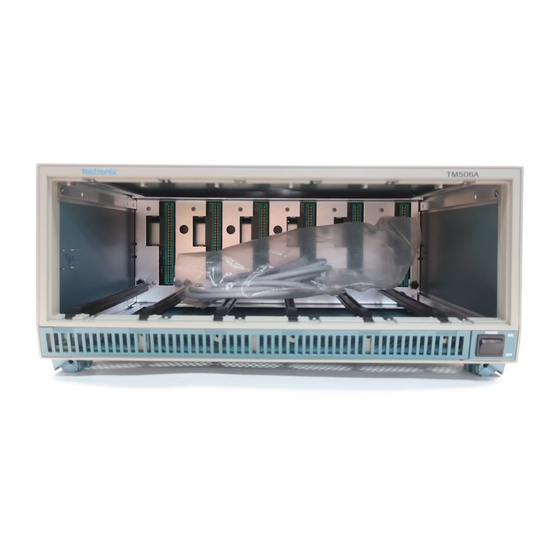
This is necessary to plug-in support rails and out the access panel. Replace the insure proper cooling. power module bottom cover. CABLE RACEWAY TO REAR PANEL 6929-3 Fig. 2-2. TM 506A front view. - Page 16 Fig. 2-3. TM 506A rear panel. If the rack has positive internal pressure for cooling pur The TM 506A, Option 10, fits a standard 19-inch side poses, the mainframes must have all compartments filled cabinet, rack or console. Spacing inside the front rails must with plug-ins or blank front panels (available from Tektronix, be at least 17 3/4 inches.
- Page 17 Operating Instructions — TM 506A § <h § <3 £ — 1 ä Fig. 2-4. TM 506A, overall dimensions.
-
Page 18: Plug-In Installation And Removal
Operating Instructions — TM 506A Rack Adjustments. After installing the instrument in the rack, binding in the rack slides may occur if the slides are not properly adjusted. Slide the instrument from the rack until the front panel is about 10 inches from the front of the rack. - Page 19 Operating Instructions — TM 506A...
- Page 20 Operating Instructions — TM 506A STOP LATCH HOLES ‘ ENGAGES WITH MONITOR RACK RELEASE LATCH (2234-09) 2950-07 Fig. 2-7. Rackmount slide detail. If the rack has tapped holes, the bar nuts are not required. Fig. 2-8. Rackmounting slide details.
- Page 21 Operating Instructions — TM 506A TO INSTALL: 1. Pull the slide-out track sec tion to the fully extended position. 2. Insert the instrument chassis sections into the slide-out sections. 3. Press the stop latches and push the instrument toward the rack until the latches snap into their holes.
-
Page 22: Family Compatibility
GROVE 6929-12 Fig. 2-10. Plug-in installation and removal. location. An entire TM 506A can be set up in this manner for Family Compatibility specific work functions. For extra barriers, order Tektronix Mechanically, TM 500 plug-in modules are very similar to Part No. -
Page 23: Option 02
This gives the system designer as much flexibility as possi If the Tektronix instrument is shipped to a Tektronix Ser ble. Refer qualified service personnel to the Maintenance vice Center for service or repair, attach a tag showing section of this manual for Option 02 installation information. -
Page 25: The Following Servicing Instructions
THE FOLLOWING SERVICING INSTRUCTIONS QUALIFIED PERSONNEL ONLY. TO AVOID PERSONAL INJURY, DO NOT PERFORM ANY SERVICING OTHER THAN THAT CONTAINED OPERATING INSTRUCTIONS UNLESS YOU ARE QUALIFIED TO REFER TO OPERATORS SAFETY SUMMARY AND SERVICE SAFETY SUMMARY PRIOR TO PERFORMING ANY SERVICE. -
Page 27: Maintenance
Section 3 — TM 506A MAINTENANCE Cleaning Introduction This instrument should be cleaned as often as operating This section contains information on preventive mainte conditions require. Loose dust accumulated on the outside nance and instrument disassembly. of the instrument can be removed with a soft cloth or small brush. - Page 28 Maintenance — TM 506A interface circuit board, remove the plug-in guide rails shown in Fig. 3-3. Next remove the interface circuit board support by removing the screws shown in Fig. 3-4 and Fig. 3-6. Be fore removing the main interface circuit board, make certain the connections to the board are either unplugged or unsol ...
- Page 29 1. Remove the heat sink. To remove the heat sink: 2. Remove the rear panel. 1. Disconnect the TM 506A from the power source. 3. Tag and disconnect all leads. 2. Disconnect the leads to the high-power series-pass transistors. (The transistors are shown in Fig. 3-7.) 4.
- Page 30 Maintenance — TM 506A 6929-6 Fig. 3-4. Removal of the interface circuit board support.
-
Page 31: Troubleshooting
However, if a plug-in is defective, be sure that the problem is not in the TM 506 A: 3. Turn off the power to the TM 506A and use an ohm 1. Check the power supply fuses. These are located at meter to test the series-pass transistor that drives the the rear panel. - Page 32 Maintenance — TM 506A 6929-9 Fig. 3-7. Series pass transistor locations. The high power compartment series pass transistors Q450 and Q650 are on the right side of the heat sink. Q650 is the upper transistor.
- Page 33 Maintenance — TM 506A...
- Page 34 Maintenance — TM 506A REMOVE THESE SCREWS „ £ 6929-10 Fig. 3-9. Transformer assembly attaching screws.
-
Page 35: Options
Section 4 — TM 506A OPTIONS Introduction 3. Pin assignments for individual plug-ins will be found in the appropriate instruction manual. Option 02 provides rear interface connections at the rear panel and Option 10 provides rack mounting capabilities. Information on Option 02 is found below. Information on 4. -
Page 37: Replaceable Electrical Parts
If a part you have ordered has been replaced with a new or assemblies and parts). improved part, your local Tektronix, Inc. Field Officeor represen tative will contact you concerning any change in part number. Chassis-mounted parts have no assembly number prefix and are located at the end of the Electrical Parts List. - Page 38 71400 BUSSMANN 114 OLD STATE RD ST LOUIS MO 63178 DIV OF COOPER INDUSTRIES INC PO BOX 14460 80009 TEKTRONIX INC 14150 SW KARL BRAUM DR BEAVERTON OR 97077 PO BOX 500 MS 53-111 81483 INTERNATIONAL RECTIFIER 9220 SUNSET BLVD...
- Page 39 Replaceable Electrical Parts — TM 506A Seri al/Assembly No. Mfr. Tektronix Mfr. Part No. Effective Dscont Name & Description Code Conponent No. Part No. 671-0621-00 671-0621-00 CIRCUIT BD ASSY:MAIN INTERFACE 80009 80009 671-0622-00 671-0622-00 CIRCUIT BD ASSY:POWER SUPPLY CIRCUIT BD ASSY:MAIN INTERFACE...
- Page 40 Replaceable Electrical Parts - TM 506A Tektronix Seri al /Assembly No. Mfr. Mfr. Part No. Dscorrt Name & Description Code Component No. Part No. Effective CONN,RCPT,ELEC:CKT BD, 28/56 CONTACT 31781 303-056-520-301 A10J3080 131-1078-00 SJE491 A10Q3005 151-0462-00 TRANSIST0R:PNP,SI,T0-220 04713 A10R2047 315-0100-00 RES, FXD,FILM: 10 OW.5%,0.25W...
- Page 41 Replaceable Electrical Parts - TM 506A Mfr. Serial/Assembly No. Tektronix Mfr. Part No. Effective Code Dscorrt Name & Description Conponent No. Part No. 80009 151-0918-00 Q3067 151-0918-00 B010100 B011072 TRANSISTOR:PNP POWER, 15A.80V 04713 MJF2955 03067 151-0938-00 B011073 TRANSISTOR:PNP POWER,10A.90V 80009...
-
Page 43: Diagrams And Circuit Board Illustrations
Values less than one are in microfarads Other ANSI standards that are used in the preparation (Z/F). of diagrams by Tektronix, Inc. are: Resistors ~ Ohms (Q). The information and special symbols below may appear in this manual. - Assembly Numbers and Grid Coordinates The schematic diagram and circuit board component location illustration have grids. - Page 46 TM 506A J1025 Table 6-1 J1 065 J1070 USER INTERFACE <?> MAIN INTERFACE BO., ASSEMBLY A10 CIRCUIT SCHEMATIC BOARD NUMBER LOCATION LOCATION J3015 J3025 ►> |CX1J J3040 (\l i J3055 J3065 J3080 A1 0 also shown on Diagram 2 S •...
- Page 47 TM 506A TN506A USER INTERFACE...
- Page 48 TM 506A...
- Page 49 Table 6-2 MAIN INTERFACE <£> — MAIN INTERFACE BD., ASSEMBLY A10 CIRCUIT SCHEMATIC BOARD CIRCUIT SCHEMATIC BOARD LOCATION LOCATION NUMBER LOCATION LOCATION NUMBER J1065 C2011 J1070 C2013 C2014 J1070 J2041 C2019 C2021 J2043 J2043 C2023 J2045 C2037 J2079 C2038 J2079 C2041 J3015 C2043...
- Page 50 TM 506A □ TFI506A MAIN INTERFACE...
- Page 51 TM 506A F1 005 C2055 C2041 F2005 ® F3005 C30-41 C3055 z ,./" C3025 CR301 1 C4055 C^0*t1 J5055 J5051 J50*+5 J50*t1 J5031 J5025 J5021 J5015J5011 J5005 Fig. 6-2. A11 — Power Supply circuit board assembly.
- Page 52 Table 6-3 POWER SUPPLY — POWER SUPPLY BD.» ASSEMBLY A1 1 CIRCUIT SCHEMATIC BOARD CIRCUIT SCHEMATIC BOARD LOCATION NUMBER LOCATION LOCATION NUMBER LOCATION C2041 J5031 J5041 C2055 C3025 J5045 C3041 J5051 J5055 C3055 C4041 R1025 C4055 R3025 R3031 CR3011 CR4005 S500 (CHASSIS) S600...
- Page 53 TM 506A FL500 F1085 2.5A J5051-1 J5021-1 CR3011 RI 025 C2041 FL500 SELECTOR LOGIC F2005 2.5A J5045- J5015-1 100UAC A-B, C-D, E-F -L-CSOf] T'4700 120UAC B-D, E-F nftJN INTERFACE J5055- 220UAC A-B, D-E <F B-C, D-E 240UAC F3005 CR4005 J5041-1...
-
Page 55: Replaceable Mechanical Parts
Detail Part of Assembly and/or Component Attaching parts for Detail Part If a part you have ordered has been replaced with a new or improved part, your local Tektronix, Inc. Field Office or END ATTACHING PARTS representative will contact you concerning any change in part number. - Page 56 Replaceable Mechanical Parts - TM 506A CROSS INDEX - MFR. CODE NUMBER TO MANUFACTURER Mfr. Code Manufacturer Address City, State, Zip Code 06666 GENERAL DEVICES CO INC 1410 S POST RD INDIANAPOLIS IN 46239-9632 PO BOX 39100 06915 RICHCO PLASTIC CO...
- Page 57 Replaceable Mechanical Parts - TM 506A Fig. & Mfr. Index Tektronix Serial/Asaaribly No. Code Mfr. Part No. Effective Dscont 12345 Name & Description Part ho. 80009 348-0544-00 RTNR,CAB.COVER:CORNER,TEK BLUE.PC 348-0544-00 ATTACHING PARTS 83486 ORDER BY DESCR SCREW,TPG.TF: 8-32 X 0.625, FILM,STL...
- Page 60 REV JUL 1988 TM 506A...
- Page 61 TM 506A...
- Page 62 REV JUL 1988...
- Page 63 Replaceable Mechanical Parts - TM 506A Fig. & Mfr. Index Tektronix Serial/Assenbly Mfr. Part Ho Code Part Effective Decant 12345 Name & Description GROIWET, PLASTIC . ’ BLACK,ROUND, 0.188 ID 348-0640-00 214-3026-00 SPRING,GROUND:CU BE SUPPORT.CKT BD:ALUMINUM 386-5773-00 ATTACHING PARTS SCR.ASSEM WSHR:4-40 X 0.312, PNH STL...
- Page 64 Replaceable Mechanical Parts - IM 506A Fig. & Tektronix Serial/Assartrty Mfr. Index Effect i Decant 12345 None & Description Code Mfr. Part No. Part 2-44 212-0511-00 SCREW,MACHINE: 10-32 X 3.0 HEX HD,STL 166-0434-00 INSUL SLVG,ELEC :0.19 ID X 2.25 L,MYLAR 210-0812-00 WASHER,FLAT: 0.188 ID X 0.375 00 X 0.31...
- Page 65 Replaceable Mechanical Parts - TM 506A Fig.& Index Tektronix Serial/Assembiy No. Mfr. Part No. Effective Dscont Qty 12345 Name & Description Code Mfr. Part No. 131-0955-00 CONN,RCPT,ELEC£NC,FEMALE 13511 31-279 (OPTION 02,12 ONLY) 210-0255-00 TERMINAL,LUG:0.391 ID,LOCKING,BRS CD PL 12327 ORDER BYDESCR...
- Page 67 REV MAR 1991...
- Page 68 TM 506A...
- Page 69 FIG. 4 ACCESSORIES...
- Page 70 Replaceable Mechanical Parts - TM 506A Fig. & Mfr. idex Tektronlx Serial/Assembly No. Qty 12345 Name & Description Code Mfr. Part No. Part No. Effective Discont STANDARD ACCESSORIES CABLE ASSY,PWR,:3,18AWG,115V, 98.0 L 16428 CH8481 , FH8481 161-0066-00 MDX4 FUSE,CARTRIDGE:3AG,4A, 250, SLOW BLOW...
- Page 72 MANUAL CHANGE INFORMATION At Tektronix, we continually strive to keep up with latest electronic developments by adding circuit and component improvements to our instruments as soon as they are developed and tested. Sometimes, due to printing and shipping requirements, we can ’ t get these changes immediately into printed manuals.
- Page 74 COMMITTED TO EXCELLENCE Date: June 1.1988 ______________________________________ Change Reference: CI/0688 Product: TM 506A Power Module _________________________________________________________________________________________________ Manual Part No: JQ70-6929-00 DESCRIPTION Effective for all serial numbers, Please make the following changes: Electrical Diagram Change: Schematic 3 Power Supply...
- Page 76 MANUAL CHANGE INFORMATION Tfektronix COMMOTED TO EXCELLENCE Date: ____ Efii2_24_lSß2 ____ Change Reference: _____ MSÜS23 __ Product: TM 506 A Power Module __________________________ Manual Part No: 070-6929-00 DESCRIPTION For Serial Numbers B010527 and above, please make the foltowing changes: Section 5 REPLACEABLE ELECTRICAL PARTS Change: Page 5-3...
- Page 78 Tfektronix MANUAL CHANGE INFORMATION Date: 1988 Change Reference: M6695Z _________ committed to excellence Product: TM 506A Power Module _________________________ Manual Part No . 070-6929-00 DESCRIPTION Effective Serial Number B010I09 above, please make the following changes: Electrical Parts List Change: F500...
- Page 80 COMMITTED TO EXCELLENCE Date: July 28.1988 _______________________________________ Change Reference: M67432 Q 1Q-6 9 2 9-W Product: TM 506A Power Module _________________________________________________________________________________________________ Manual Part No: — DESCRIPTION For Serial Numbers B010152 and above, please make the following changes: Operating Instructions Add: Page 2-1...
- Page 82 MANUAL CHANGE INFORMATION Tfektronix COMMITTED TO EXCELLENCE Date: July 18.1989 _________ Change Reference: M70321 REV Product: TM 506A Power Module ____________________________ Manual Part No: 070-6929-00 DESCRIPTION For Serial Numbers B010664 and above, please make the following changes: Section 5 REPLACEABLE ELECTRICAL PARTS...
- Page 84 Replaceable Mechanical Parts - TM 506A Fig. & Serial/Assembiy No. Mfr. idex Tektronix Code Mfr. Part No. Effective Discont Qty 12345 Name & Description Part No. STANDARD ACCESSORIES CABLE ASSY,PWR,:3,18AWG,115V, 98.0 L 16428 CH8481 , FH8481 161-0066-00 FUSE,CARTRIDGE:3AG,4A, 250, SLOW BLOW...
- Page 86 Manual Change Information Tektronix COMMITTED TO EXCELLENCE Date: Mar 25. 1991 Change Reference: ______ M74643 Product: TM 5Q6A Power Module ___________________________ Manual Part Number: 070-6929-00 Description Please use the attached page to replace the equivalent page in your manual. Page 1 of 1...
- Page 88 Replaceable Mechanic* 1 Parts - TM 506A Fig. & Mfr. Index Tefctnxiix Serial / Assam iy Code Mfr. Part No. Part No. Effective Cfecont Qty — 12345 Na» & Description 348-0544-00 80009 348-0544-00 RTNR,CAB.COVER:CORNER.TEK BLUE.PC ATTACHING PARTS 83486 ORDER BY DESCR 213-0782-00 SCREW.TPG.TF: 8-32 X 0.625.FILH.STL...
Need help?
Do you have a question about the TM 506A and is the answer not in the manual?
Questions and answers