Table of Contents
Advertisement
Quick Links
Instruction Manual
PSC1125
Digital Television Parallel-to-Serial Converter
071-0146-05
Warning
The servicing instructions are for use by qualified
personnel only. To avoid personal injury, do not
perform any servicing unless you are qualified to
do so. Refer to all safety summaries prior to
performing service.
Advertisement
Table of Contents

Related Manuals for Tektronix PSC1125


Summary of Contents for Tektronix PSC1125
- Page 1 Instruction Manual PSC1125 Digital Television Parallel-to-Serial Converter 071-0146-05 Warning The servicing instructions are for use by qualified personnel only. To avoid personal injury, do not perform any servicing unless you are qualified to do so. Refer to all safety summaries prior to...
- Page 2 Copyright © Sony/Tektronix Corporation. All rights reserved. Copyright © Tektronix, Inc. All rights reserved. Tektronix products are covered by U.S. and foreign patents, issued and pending. Information in this publication supercedes that in all previously published material. Specifications and price change privileges reserved.
- Page 3 Tektronix, with shipping charges prepaid. Tektronix shall pay for the return of the product to Customer if the shipment is to a location within the country in which the Tektronix service center is located.
- Page 4 For product support outside of North America, contact your local Tektronix distributor or sales office. Service Contact your local Tektronix distributor or sales office. Or visit Support our web site for a listing of worldwide service locations. http://www.tek.com For other...
- Page 5 H Eliminates unexpected service expenses For Information and Ordering For more information or to order Service Assurance, contact your Tektronix representative and provide the information below. Service Assurance may not be available in locations outside the United States of America.
-
Page 7: Table Of Contents
Maintenance Tektronix Service Offerings ......... - Page 8 Table of Contents Replaceable Parts List Parts Ordering Information ......... 8–1 Using the Replaceable Parts List .
- Page 9 Table of Contents List of Figures Figure 1–1: Block diagram ........1–1 Figure 2–1: PSC 1125 front panel .
- Page 10 Table of Contents List of Tables Table 1–1: Standard accessories ......1–2 Table 1–2: Files on the TSG1001 Signal Library floppy disk .
- Page 11 General Safety Summary Review the following safety precautions to avoid injury and prevent damage to this product or any products connected to it. To avoid potential hazards, use this product only as specified. Only qualified personnel should perform service procedures. While using this product, you may need to access other parts of the system.
- Page 12 General Safety Summary Symbols and Terms Terms in this Manual. These terms may appear in this manual: WARNING. Warning statements identify conditions or practices that could result in injury or loss of life. CAUTION. Caution statements identify conditions or practices that could result in damage to this product or other property.
- Page 13 Service Safety Summary Only qualified personnel should perform service procedures. Read this Service Safety Summary and the General Safety Summary before performing any service procedures. Do Not Service Alone. Do not perform internal service or adjustments of this product unless another person capable of rendering first aid and resuscitation is present.
- Page 14 Service Safety Summary viii PSC 1125 Digital Television Parallel-to-Serial Converter Instruction Manual...
-
Page 15: Figure 1-1: Block Diagram
BTA S-004A (SMPTE 292M). Because the converter accepts output signals from the Tektronix TSG1001 Multi-format Test Signal Generator, you can generate a digital television signal by using the converter in combination with the generator. -
Page 16: Table 1-1: Standard Accessories
Instruction Manual 071 0146 XX U.S. Power Cord 161 0216 XX 3.5 inch floppy disk, TSG1001 Signal Library for PSC1125 063 2986 XX 2 cables, 25 pin, D type (for TSG1001 connection) 174 3882 XX (These cables should be installed as described on page 1-6.) -
Page 17: Installation
After connecting the power, make sure that the fan on the rear panel is working. If the fan is not working, turn off the power by disconnecting the power cable from the AC voltage line and contact Tektronix for servicing. PSC 1125 Digital Television Parallel-to-Serial Converter Instruction Manual... -
Page 18: Signal
Getting Started Downloading Signal The TSG1001 signal library floppy disk (Tektronix part number 063-2986-XX) Libraries is supplied with the converter. This disk contains the following items: H SMPTE 260M/274M/296M download files which comply with the SDP1000 V2.3 or above H Special tools to let the TSG1001 generate signals which comply with SMPTE 260M/274M/296M See Table 1–2 for descriptions of the signals on the disk. - Page 19 Getting Started An example for downloading the signal libraries follows: To download the signal libraries from a PC to the TSG1001, you should install the SDP1000 communication utility, COM1000, into the PC. If the necessary communication utility is not already stored in the directory, sdp1000, refer to the TSG1001 and SDP1000 product documentation.
- Page 20 Getting Started Making Connections Follow these steps to connect the converter, the TSG1001, and the equipment to which you want to provide the signal. 1. Using one of the cables supplied with the converter, connect the G/Y connector on the TSG1001 to the Y connector on the converter. 2.
-
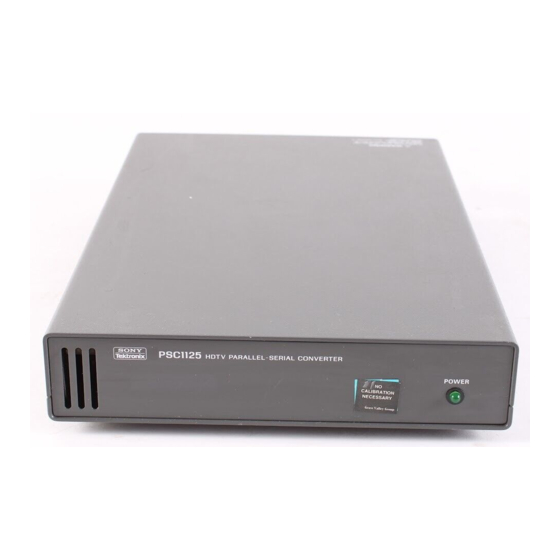
Page 21: Figure 2-1: Psc 1125 Front Panel
Operating Basics This section provides an overview of the front-panel features and rear-panel connectors. Also included are procedures for cleaning the exterior of the instrument. Front Panel Overview Figure 2–1 shows the front panel of the converter. Power indicator Figure 2-1: PSC 1125 front panel Power Indicator The LED will light in green when the power is turned on. -
Page 22: Figure 2-2: Psc 1125 Rear Panel
Operating Basics Rear Panel Overview Figure 2–2 shows the rear panel of the converter. Parallel Digital Y Serial Digital Input connector Output connectors Power connector Parallel Digital P Input connector Figure 2-2: PSC 1125 rear panel Power Connector This instrument operates from a single-phase power source with one current-car- rying conductor at or near earth-ground (the neutral conductor). -
Page 23: Customer Maintenance
Use a 75% isopropyl alcohol solution or a general purpose detergent-and-water solution. Rinse with deionized water. Before using any other type of cleaner, consult your Tektronix Service Center or representa- tive. WARNING. To avoid potential electric shock hazard or damage to the converter circuits, do not allow any moisture inside the converter during external cleaning;... - Page 24 Customer Maintenance 1. Remove loose dust on the outside of the converter with a lint free cloth. 2. Remove remaining dirt with a lint free cloth dampened in a general purpose detergent-and-water solution. Do not use abrasive cleaners. PSC 1125 Digital Television Parallel-to-Serial Converter Instruction Manual...
-
Page 25: Table 3-1: Digital Video Interface
Specifications Tables ** ** through ** ** list the electrical specifications for the PSC 1125 Digital Television Parallel-to-Serial Converter. Performance require- ments are generally quantitative and can be tested by qualified service personnel. Reference information describes useful operating parameters and typical characteristics and performance. -
Page 26: Figure 3-1: Parallel Input Connector (Y, Pb/Pr)
Specifications Table 3-1: Digital video interface (Cont.) Characteristic Reference information Number of outputs 2 (same signals, separate drivers) Bit rate 1.4835 G to 1.485 G bps Serial amplitude 800 mV "10 % (at 75 W load) Rise and fall times v 270 ps (20 to 80 % amplitude points) Jitter v 135 ps (alignment jitter) -
Page 27: Figure 3-2: Data-To-Clock Relation (Parallel Input)
Specifications Tset Thold Data D0 to D9 (Y, P D0 to D9 Clock (Y) MSB: D9 LSB: D0 Figure 3-2: Data to clock relation (parallel input) Table 3-3: AC power source Characteristic Reference information Range 100 to 240 VAC, 50 to 60 Hz Maximum power 30 VA (approximately 30 Watts) Supply connection... - Page 28 Specifications Table 3-5: Environmental characteristics (Cont.) Characteristic Standard and reference information Altitude Operating 4,500 m Maximum operating temperature decreases 1 C each 300 m above 1,500 km. Non operating 15,000 m Relative humidity Operating 20 % to 80 % (No condensation) Non operating 5 % to 90 % (No condensation) Vibration...
- Page 29 Specifications Table 3-6: Certifications and compliances (Cont.) Category Standards or description EC Declaration of Conformity - Compliance was demonstrated to the following specification as listed in the Official Journal of the Low Voltage European Union: Low Voltage Directive 73/23/EEC, amended by 93/68/EEC EN 61010 1:1993 Safety requirements for electrical equipment for measurement control and laboratory use.
-
Page 30: Table 3-7: Physical Characteristics
Specifications Table 3-7: Physical characteristics Characteristics Descriptions Dimensions Height 43.4 mm (1.71 in) Width 206.2 mm (8.12 in) Depth 336.0 mm (13.2 in) Weight approximately 2.5 kg (approximately 5.5 lbs) Shipping approximately 4.1 kg (approximately 9 lbs) PSC 1125 Digital Television Parallel-to-Serial Converter Instruction Manual... - Page 31 Warning The following servicing instructions are for use only by qualified personnel. To avoid injury, do not perform any servicing other than that stated in the operating instructions unless you are qualified to do so. Refer to all Safety Summaries before performing any service.
-
Page 33: Table 4-1: Required Equipment
Tektronix part no. 012 0432 00 75 W coaxial cable Serial digital video cable less Signal interconnection than 1 m in length 75 W terminator Tektronix part no. 011 0 02 00 Signal interconnection PSC 1125 Digital Television Parallel-to-Serial Converter Instruction Manual... -
Page 34: Table 4-2: Files On The Tsg1001 Signal Library Floppy Disk
Qty. Required precision Recommended equipment Purpose Signal set floppy disk TSG1001 BTA S 002A Signal Tektronix part no. 063 2986 XX, Signal set data to be down Library Supplied with the converter loaded to the TSG1001 generator for tests IBM PC compatible... - Page 35 Performance Verification Table 4-2: Files on the TSG1001 Signal Library floppy disk (Cont.) Library DNL file File description Field rates 1125.DNL HDTV/ SMPTE 274M Both 59.94 Hz and 60 Hz 750_60.DNL HDTV/ SMPTE 296M 60 Hz 750_59.DNL HDTV/ SMPTE 296M 59.94 Hz MULTI.DNL HDTV/ SMPTE 274M/296M...
- Page 36 Performance Verification <Return> 2. Insert the signal set floppy disk into the floppy disk drive on the PC. Type: a: <Return> The screen for the download files appears. 3. Select the MULTI (HDTV/SMPTE 274M/296M 59.94 Hz and 60 Hz) signal set file which provides SMPTE 274M/296M data with 59.94 Hz and 60 Hz field rate.
-
Page 37: Figure 4-1: Performance Check Initial Hookup
Performance Verification 75 W terminator 764 digital audio monitor rear panel 75 W coaxial cable Parallel signal cable 75 W coaxial cable PSC1125 TSG1001 generator rear panel converter rear panel WFM1125 waveform monitor Option 0C rear panel Parallel signal cable... - Page 38 Performance Verification Embedded Audio Check Only trained service technicians should perform the following procedure. Use the test hookup and equipment controls from the previous test. CAUTION. In the following procedures, you remove the converter top cover and access an internal module. Be sure to disconnect the power cable from the AC power line connector when you remove or install the cover or when you access the internal module.
- Page 39 Performance Verification 10. In the view, check Highest true pks are –20 dBFS. 11. Press the FORMATS button on the TSG1001 generator front panel to set the FORMAT to SMPTE 274M/60Hz. 12. Repeat steps from 7 to 10 for SMPTE 274M/60Hz. 13.
-
Page 40: Figure 4-2: Eye Pattern Test Initial Hookup
50 W coaxial cable SMA to BNC adapter 75 to 50 W Sampling oscilloscope minimum loss pad Parallel signal cable PSC1125 TSG1001 generator rear panel converter rear panel SMA to BNC adapter Parallel signal cable 75 to 50 W 50 W coaxial cable... - Page 41 Performance Verification 2. Set the equipment controls: a. Set the TSG1001 generator signal output to ZONE PLATE. b. Set the oscilloscope controls: Vertical ......CH1 Coupling .
-
Page 42: Figure 4-3: Example Of Eye Pattern For An Acceptable Output Signal
Performance Verification Figure 4-3: Example of eye pattern for an acceptable output signal 4. Exchange the cable connection on the oscilloscope: a. Disconnect the coaxial cable from the OUT1 connector on the sampling head of the oscilloscope. b. Disconnect the coaxial cable from the TRIGGER DIRECT INPUT connector on the oscilloscope, and then connect it to the CH1 connector on the sampling head of the oscilloscope, through the 75-to-50 W attenuator. - Page 43 Performance Verification 5. Check that the OUT2 eye pattern displayed on the oscilloscope is fully open (see Figure 4–3). 6. Retain the connections and controls when you go on to the next performance test procedures. Check Eye Pattern for Only trained service technicians should perform the following procedure: HK 101 unused terminal CAUTION.
- Page 44 Performance Verification 3. Restore the internal cable connection: a. Disconnect the AC power cable from the AC power line connector. b. Disconnect the cable connected to the HK-101 OUT1 terminal and then connect it to the HK-101 OUT 3 terminal. c.
-
Page 45: Figure 5-1: Location Of J400
Setting Sound Packets The converter provides the feature to embed sound packets in the output serial digital data. This feature is available through the jumpers of J400 connector pin on the A10 board. This section describes how to configure the jumpers for setting sound packets. -
Page 46: Figure 5-2: Jumper Configuration For Selecting Sound Packets
Adjustment Procedures Jumper Configuration For J300149 - J310100 You can select silence, 1 kHz tone, or no sound packets (default) that is embedded in the output serial data and the field rate to 59.94 MHz by changing the jumper setting. Figure 5–2 shows J400 connector pin and the functions set by the jumpers. -
Page 47: Figure 5-3: Jumper Configuration For Selecting Sound Packets
Adjustment Procedures For J310101 and Above You can select silence, 1 kHz tone, or no sound packets (default) that is embedded in the output serial data by changing the jumper setting. Figure 5–3 shows J400 connector pin and the functions set by the jumper. Insert and remove the jumper in /from the jumper pin pairs to achieve that function. - Page 48 Adjustment Procedures PSC 1125 Digital Television Parallel-to-Serial Converter Instruction Manual...
-
Page 49: Table 6-1: Test Equipment
Table 6-1: Test equipment Item description Minimum requirements Example Digital multimeter (DMM) DC volt range: 0.1 to 20 V, Tektronix DMM252 Accuracy: "0.5 % A set of test leads Supplied with the DMM PSC 1125 Digital Television Parallel-to-Serial Converter Instruction Manual... -
Page 50: Figure 6-1: A10 Board View And Test Points
Adjustment Procedures Voltage Adjustment Preparation To perform the display adjustments, you must first remove the top cover and shield cover. For removal and installation procedures, refer to Top Cover and Shield Cover on page 7–9. After you have removed the top cover and shield cover, find the test points on the A10 board and the variable resistor on the Power Supply board. -
Page 51: Table 6-2: Test Points And Voltage Ranges
Adjustment Procedures Adjustment WARNING. To avoid serious injury, do not touch exposed connections or components when operating the instrument with the protective enclosure removed. Dangerous potentials exist at several points within the converter. 1. Connect the power cord to turn on the power. 2. - Page 52 Adjustment Procedures PSC 1125 Digital Television Parallel-to-Serial Converter Instruction Manual...
-
Page 53: Tektronix Service Offerings
Refer to page 7–20. Tektronix Service Offerings Tektronix provides service to cover repair under warranty as well as other services that may provide a cost-effective answer to your service needs. Whether providing warranty repair service or any of the other services listed below, Tektronix service technicians are well equipped to service the converter. -
Page 54: Preparation
Maintenance exchange module from the Beaverton, Oregon service center, typically within 24 hours. For more information, contact your local Tektronix service center or sales engineer for more information on any of the repair or adjustment services just described. Preparation Before doing any of the procedures in the Maintenance section, note the following: H Only trained service technicians should perform these procedures. -
Page 55: Table 7-1: Relative Susceptibility To Static-Discharge Damage
Maintenance 7. Do not slide the modules over any surface. 8. Avoid handling modules in areas that have a floor or work-surface covering capable of generating a static charge. 9. Do not use high-velocity compressed air when cleaning dust from modules. Table 7–1 lists the relative susceptibility of various classes of semiconductors. -
Page 56: Inspection And Cleaning
Use a 75% isopropyl alcohol solution as a cleaner, and rinse with deionized water. Before using any other type of cleaner, consult your Tektronix Service Center or representative. To prevent damaging converter components, do not use high-pressure com- pressed air when cleaning dust from the interior of the converter. -
Page 57: Table 7-2: External Inspection Check List
Maintenance Table 7-2: External inspection check list Item Inspect for Repair action Cabinet, front panel, Cracks, scratches, deformations, Replace defective module. and cover damaged hardware or gaskets Connectors Broken shells, cracked insulation, Replace defective modules. and deformed contacts; dirt in Clear or wash out dirt. - Page 58 Maintenance Table 7-3: Internal inspection check list (Cont.) Item Inspect for Repair action Solder connections Cold solder or rosin joints Resolder joint and clean with isopropyl alcohol. Capacitors Damaged or leaking cases; Remove damaged module and corroded solder on leads or replace with a new module from terminals the factory.
- Page 59 Maintenance 7. Dry all parts with low-pressure, deionized air. 8. Dry all components and assemblies in an oven or drying compartment using low-temperature (51.7_ C to 65.6_ C, 125_ F to 150_ F) circulating air. PSC 1125 Digital Television Parallel-to-Serial Converter Instruction Manual...
-
Page 60: Table 7-4: Equipment Required
Maintenance Removal and Installation Procedures This subsection describes removing and installing mechanical and electrical modules. Preparation This subsection contains the following information: H Safety and ESD information needed to properly do the procedures that follow H A list of equipment required when removing modules H Procedures for removing and installing electrical and mechanical modules WARNING. - Page 61 Maintenance Removal and Installation This group contains the following procedures: Procedure Groups H Top Cover and Shield Cover H Power Indicator Module H Noise Filter and Power Supply H Fan Module H A10 board and Connectors H Bottom Cover and Front Panel Top Cover and Shield Equipment #1 Phillips screwdriver...
-
Page 62: Figure 7-1: Top Cover And Shield Cover Removal
Maintenance Top Cover Shield Cover M3x6MM FLH Screws (4) Figure 7-1: Top cover and shield cover removal Power Indicator When you replace the LED or interconnect cable, you will need a soldering iron to disassemble the power indicator module. Equipment Needle nose pliers required Soldering iron... -
Page 63: Figure 7-2: Removal Of Power Indicator Module Holder Attachment
Maintenance Remove holder attachment Figure 7-2: Removal of power indicator module holder attachment Release and remove holder Pull LED away Figure 7-3: Removal of power indicator module LED and holder 7-11 PSC 1125 Digital Television Parallel-to-Serial Converter Instruction Manual... -
Page 64: Figure 7-4: Power Indicator Assembly Interconnect Cable Removal
Maintenance 3. Disassemble the power indicator module: a. Slide the two tubes along the ribbon interconnect cable until the connection between the LED lead and cable is exposed. b. Unsolder the two interconnect cables attached to the LED leads. See Figure 7–4. -
Page 65: Figure 7-5: Noise Filter And Power Supply Module Removal
Maintenance Noise Filter Module Removal. 1. Remove noise filter module: (See Figure 7–5) a. Remove the two interconnect cables attached to the L and N terminals of the noise filter module. b. Using a 7 mm size nut driver, remove the nut attaching the ground wire to the chassis. -
Page 66: Figure 7-6: Fan Module Removal
Maintenance Power Supply Module Removal. 3. Remove power supply module: (See Figure 7–5) a. Disconnect the interconnect cable at CN2 on the Power Supply board. b. Disconnect the interconnect cable at CN1 on the Power Supply board. c. Using a 7 mm size nut driver, remove the nut attaching the ground wire to the chassis. - Page 67 Maintenance 2. Reinstallation: Install the fan module by reversing step 1. CAUTION. When you connect the ribbon cable to the connector on the circuit board, make sure that the index on the ribbon cable connector is aligned to the index marked near the connector pin on the circuit board. A10 Board and Equipment #1 Phillips screwdriver...
-
Page 68: Figure 7-7: A10 Module Removal
Maintenance OUT3 (to rear panel OUT2 connector) J100 (to Y parallel OUT2 (to rear panel OUT1 connector) connector) OUT1 (unused) J200 (to Pb/Pr parallel connector) A10 Board M3x8MM PN HK 101 Screws (5) J014 (to Fan) J018 (to Power Indicator) M2.6x6MM PNH Screws (2) J010 (to Power Supply CN2) Figure 7-7: A10 module removal... -
Page 69: Figure 7-8: Input And Output Connector Removal
Maintenance M2.6x6MM PNH Screws (8) 4.8MM HEX Spacer Post (4) W300 (to HK 101 OUT 2) W400 (to HK 101 OUT 3) W100 (to A10 J100) W200 (to A10 J200) Figure 7-8: Input and output connector removal Bottom Cover and Front Equipment #1 Phillips screwdriver Panel... -
Page 70: Figure 7-9: Front Panel And Bottom Cover Removal
Maintenance M3x5.5MM HEX Nuts (2) M3x6MM FLH Screws (4) Figure 7-9: Front panel and bottom cover removal 7-18 PSC 1125 Digital Television Parallel-to-Serial Converter Instruction Manual... -
Page 71: Repackaging
H A complete description of the service required Seal the shipping carton with an industrial stapler or strapping tape. Mark the address of the Tektronix Service Center and your own return address on the shipping carton in two prominent locations. -
Page 72: Troubleshooting
Maintenance Troubleshooting This subsection contains a troubleshooting tree designed to help you isolate faulty modules in the converter. 7-20 PSC 1125 Digital Television Parallel-to-Serial Converter Instruction Manual... - Page 73 Maintenance Start Turn on the power Power Replace Power Supply Waveform Fan works indicator lights and adjust the voltage displayed Power Replace Power Indicator indicator lights Voltage at all test Adjust output voltage of points on the A10 the Power Supply board are with proper range Fan works...
- Page 74 Maintenance 7-22 PSC 1125 Digital Television Parallel-to-Serial Converter Instruction Manual...
-
Page 75: Parts Ordering Information
This section contains a list of the replaceable modules for the converter. Use this list to identify and order replacement parts. Parts Ordering Information Replacement parts are available through your local Tektronix field office or representative. Changes to Tektronix products are sometimes made to accommodate improved components as they become available and to give you the benefit of the latest improvements. - Page 76 Items in this section are referenced by figure and index numbers to the exploded view illustrations that follow. Tektronix part number Use this part number when ordering replacement parts from Tektronix. 3 and 4 Serial number Column three indicates the serial number at which the part was first effective. Column four indicates the serial number at which the part was discontinued.
- Page 77 Replaceable Parts List Manufacturers cross index Mfr. code Manufacturer Address City, state, zip code 80009 TEKTRONIX INC 14150 SW KARL BRAUN DR BEAVERTON OR 97077-0001 PO BOX 500 80126 PACIFIC ELECTRICORD CO 747 W REDONDO BEACH GARDENA CA 90247-4203 PO BOX 10...
- Page 78 Replaceable Parts List Replaceable parts list Fig. & Tektronix part Serial no. Serial no. Mfr. index number effective discont'd code Name & description Mfr. part number number Main chassis and circuit boards 211 0785 XX SCREW,MACHINE:M3X6MM L,FLH,STL,BLK ZN PL,CROSS 80009...
-
Page 79: Figure 8-1: Main Chassis And Circuit Boards
Replaceable Parts List See Figure 8-3 for Detailed Rear Panel Assembly View See Figure 8-2 for Detailed LED Assembly View Figure 8-1: Main chassis and circuit boards PSC 1125 Digital Television Parallel-to-Serial Converter Instruction Manual... - Page 80 Replaceable Parts List Replaceable parts list Fig. & Tektronix part Serial no. Serial no. Mfr. index number effective discont'd code Name & description Mfr. part number number Front panel and power indicator 333 4271 XX PANEL,FRONT 80009 3334271XX 150 0248 XX...
-
Page 81: Figure 8-2: Front Panel And Power Indicator
Replaceable Parts List Figure 8-2: Front panel and power indicator PSC 1125 Digital Television Parallel-to-Serial Converter Instruction Manual... - Page 82 Replaceable Parts List Replaceable parts list Fig. & Tektronix part Serial no. Serial no. Mfr. index number effective discont'd code Name & description Mfr. part number number Rear panel and grounding 220 0212 XX NUT,PLAIN,HEX:M3X5.5MM HEX,STL,ZN-C,1-SHU 80009 2200212XX 129 1051 XX SPACER,POST:4.8MM L,4-40INT/4-40EXT,STL 4.8MM HEX...
-
Page 83: Figure 8-3: Rear Panel And Grounding
Replaceable Parts List Figure 8-3: Rear panel and grounding PSC 1125 Digital Television Parallel-to-Serial Converter Instruction Manual... - Page 84 ADAPTER CONN:2 TO 3,125V,15A,41-13213 80009 1030013XX 161 0216 XX CABLE ASSY,PWR,:3,18 AWG,2.5M L,BLACK 80126 C7120-25M-BL (STANDARD ONLY) 063 2986 XX 3.5",DISK,TSG1001 SIGNAL LIBRARY FOR PSC1125 80009 0632986XX 174 3882 XX CA ASSY,SP,ELEC:12PAIR TWIST,W/SHILD,100CM L 80009 1743882XX For cable interconnections, see Figure 9-1. 8-10...
-
Page 85: Figure 9-1: Interconnections
Diagrams This contains the block diagram and the interconnection diagram for the PSC 1125 Digital Television Parallel-to-Serial Converter. W018 J014 J018 OUT 1 (unused) SERIAL OUT 1 W300 OUT 2 HK 101 Parallel To Serial Convertor W400 SERIAL OUT 3 OUT 2 J010 J120... -
Page 86: Figure 9-2: Block Diagram
Diagrams Parallel To Serial Convertor PARALLEL SERIAL OUT 1 ECL to TTL TTL to LVCMOS HK 101 Translator Translator PARALLEL SERIAL PB/PR OUT 2 Setup Generator Reset Circuit (FPGA) Power Supply Noise Filter Figure 9-2: Block diagram PSC 1125 Digital Television Parallel-to-Serial Converter Instruction Manual... - Page 87 Index...
- Page 89 Connection, 1–6 Mechanical installation, 1–3 Module, procedures for removing and installing, 7–8 Diagrams, 9–1 Digital video interface, specifications, 3–1 Downloading, signal library, 1–4 Ordering, service, Tektronix, 7–1 Overview front panel, 2–1 Electrical specifications, 3–3 rear panel, 2–2 Electrostatic discharge preventing during maintenance, 7–2 susceptibility, 7–3...
- Page 90 7–8 Standard accessories, 1–2 Required equipment, performance verification, 4–1 Requirements for performance, adjustment, 6–1 Troubleshooting, 7–20 Safety and EMI standards, specifications, 3–4 Service ordering, Tektronix, 7–1 Setting Sound Packets, 5–1 Jumper Configuration, 5–2 Voltage adjustment, 6–2 Shipment Index-2 PSC 1125 Digital Television Parallel-to-Serial Converter Instruction Manual...
Need help?
Do you have a question about the PSC1125 and is the answer not in the manual?
Questions and answers